Table of Contents
Advertisement
Quick Links
Advertisement
Table of Contents

Related Manuals for Sanwa AU-31


Summary of Contents for Sanwa AU-31
- Page 1 AU-31 MULTITESTER INSTRUCTION MANUAL...
-
Page 2: Table Of Contents
CONTENTS AUTO-RANGE TYPE MULTITESTER MODEL AU-31 …………001 [ 1 ] FEATURES ……………………………………………………001 ……002 [ 2 ] SAFETY PRECAUTIONS:Before use, read the following safety precautions [ 3 ] MEASURING RANGE AND PERFORMANCE ……………003 [ 4 ] APPEARANCE AND NAMES OF COMPONENTS ………005 [ 5 ] HOW TO READ SCALE PLATE ……………………………006... -
Page 3: Auto-Range Type Multitester Model Au-31
AUTO-RANGE TYPE MULTITESTER MODEL AU-31 This is a circuit tester developed for measurement of small capacity electric circuits based on our advanced design and engineering technology. Electric circuits that can be measured include small communication equipment, household appliances, lighting lines (voltage), various batteries and other general electric circuits. -
Page 4: Safety Precautions:before Use, Read The Following Safety Precautions
[2] SAFETY PRECAUTIONS: Before use, read the following safety precautions This instruction manual explains how to use your multitester AU-31, safely. Before use, please read this manual thoroughly. After reading it, keep it together with the product for reference to it when necessary. -
Page 5: Measuring Range And Performance
[ 3 ] MEASURING RANGE AND PERFORMANCE Table 1 Type of Max. Scale Allowance Remarks Measurement ±3% of max. Input resistance 300mV approx.1MΩ scale. Input resistance 3/12/60/300/1000V ±3% of max. DC voltage 10MΩ min. scale. ±DCV ±4% for 1000V ±10% of max. Probe resistance 30kV 1000MΩ... - Page 6 Standard working temperature : 23 2˚C ± Standard working frequency : 50 Hz 60 Hz ∼ Standard working humidity : 45 75% RH ∼ Working temperature range 40˚C ∼ Working humidity range : 80% RH max. (No condensation) Dimensions and weight : 110(W) x 124(D) x 48(H)mm, 290g Accessories...
-
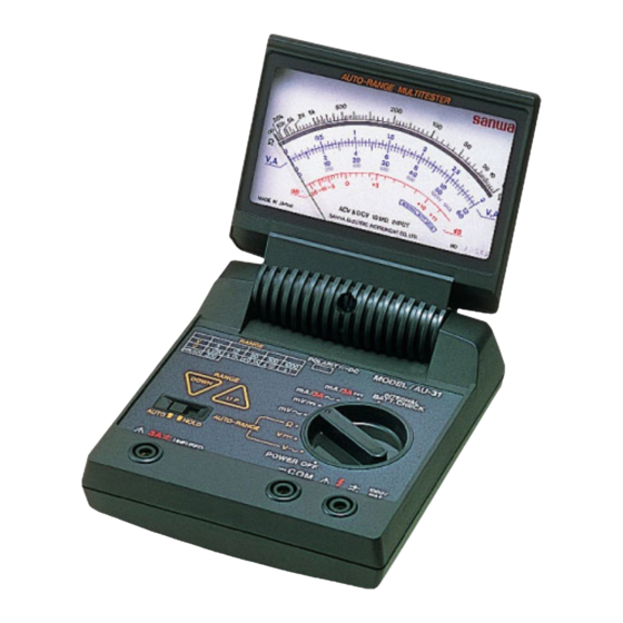
Page 7: Appearance And Names Of Components
[4] APPEARANCE AND NAMES OF COMPONENTS Indicator Pointer Range display Scale plate Manual range select switch Zero point setter Range hold switch of indicator Polarity display Function switch Measurement terminal Measurement terminal (-COM) Measurement terminal for 3A Fig. 1 Tester Red plug Black plug Test pins... -
Page 8: How To Read Scale Plate
[5] HOW TO READ SCALE PLATE Unlike other conventional testers, this tester is of auto range type and does not show a value in the current range corresponding to the position of the switch, but instead shows it on the range display. -
Page 9: How To Fix Range
Range display LED Range of DC, AC voltage (V) Range of resistance (Ω) Range of DC, AC voltage (mV) and current (mA) Fig. 4 Range Display and Example of Measurement (Example of measurement) ”position 1. Function switch: Set to“V 2. Range display: LED lit on 300 (Fig. 4) 3. -
Page 10: Preparation For Measurement
This switch is valid regardless of setting of the range hold switch and is useful for reading in a different range. Note, however, that this switch will not operate with the function switch at positions other ”and“Ω”. than“V∼”,“V [8] PREPARATION FOR MEASUREMENT For safe operation, be sure to check the position of the function switch, terminals to use and condition of connection of the test leads to the tester before starting... - Page 11 After preparation described in [8] PREPARATION FOR MEASUREMENT has been completed, measure voltage as follows. 1. Connect the black plug of the test lead to the measurement terminal (-COM) and the red plug to ( ”. 2. Turn the function switch to“V 3.
-
Page 12: 10 ] Measuring Of Ac Voltage
[10] MEASURING OF AC VOLTAGE Measurement of 0 ∼ 1000V AC (auto range) Measurement of sine wave AC voltage below 1000V max. For safe measurement, never apply a voltage above 1000V AC. Never apply an excessive voltage (more than 100 times the maximum value of the applicable range) with the range held. -
Page 13: 11 ] Measuring Of Low Frequency Output(Db)
[11] MEASURING OF LOW FREQUENCY OUTPUT(dB) The dB value is scaled in the 3V AC range and only when the impedance is 600Ω, 0dB is equal to 1mW and the output value can be read directly. (0dB = 1mW = 0.775V at 600Ω) 1. - Page 14 0Ω setter(Refer to Fig. 6 in [16] MAINTENANCE) This tester employs the constant voltage method for measurement of resistance and there is no need of 0Ω adjustment for normal measurement. To cancel resistance of the test leads in measurement in the x 1Ω range, turn the 0Ω...
-
Page 15: 13 ] Measuring Of Dc Current (Fixed Range)
[13] MEASURING OF DC CURRENT (fixed range) Measurement of 0 ∼ 300mA(0 ∼ ± ± To prevent damage to the tester and personal injury, do not measure current when the voltage exceeds 600V. ± After preparation described in [8] PREPARATION FOR MEASUREMENT has been completed, measure current as follows. -
Page 16: 14 ] Measuring Of Ac Current (Fixed Range)
[14] MEASURING OF AC CURRENT (fixed range) Measurement of 0 ∼ 300mA(0 ∼ 3A) To prevent damage to the tester and personal injury, do not measure current when the voltage exceeds 600V. ± After preparation described in [8] PREPARATION FOR MEASUREMENT has been completed, measure current as follows. -
Page 17: Replacement Of Dry Cells (Refer To Fig. 6)
[15] MAINTENANCE 15-1 Replacement of dry cells (Refer to Fig. 6): Replace dry cells if the pointer stays out of the range of “INTERNAL BATT GOOD”when the function switch is turned to “INTERNAL BATT CHECK”. 1. Remove the battery case lid. 2. -
Page 18: Cleaning And Storage
Sanwa authorized agent or distributor. Sanwa reserves the right to inspect all warranty claims to determine the extent to which the warranty policy shall apply. This warranty shall not apply to fuses, test leads, disposables batteries, or any product or parts, which have been subject to one of the following causes: 1. -
Page 19: Repair
3) Repair after the warranty period has expired: In some cases, repair and transportation cost may become higher than the price of the product. Please contact Sanwa authorized agent / service provider in advance. The minimum retention period of service functional parts is 6 years after the discontinuation of manufacture. - Page 20 SANWA ELECTRIC INSTRUMENT CO., LTD. Dempa Bldg, 4-4 Sotokanda2-Chome Chiyoda-ku, Tokyo, Japan ② 05.11 猯...
Need help?
Do you have a question about the AU-31 and is the answer not in the manual?
Questions and answers