Table of Contents
Advertisement
Quick Links
Advertisement
Table of Contents

Related Manuals for Sanwa CX506a


Summary of Contents for Sanwa CX506a
- Page 1 CX506a マルチテスタ MULTITESTER 取扱説明書 INSTRUCTION MANUAL...
-
Page 3: Table Of Contents
目 次 【1】 安全に関する項目〜ご使用前に必ずお読みください〜 ・・・・・・ 1 1−1 安全使用のための警告文 ・・・・・・・・・・・・・・・・・・・・・・・・・・・・・・・・・・・・・・・ 1 1−2 電磁界、静電界などの影響 ・・・・・・・・・・・・・・・・・・・・・・・・・・・・・・・・・・・・ 2 1−3 警告マークなどの記号説明 ・・・・・・・・・・・・・・・・・・・・・・・・・・・・・・・・・・・・ 2 1−4 最大過負荷保護入力値 ・・・・・・・・・・・・・・・・・・・・・・・・・・・・・・・・・・・・・・・・・・ 2 【2】用途と特長 ・・・・・・・・・・・・・・・・・・・・・・・・・・・・・・・・・・・・・・・・・・・・・・・・・・・・・・・・・・・・・・・ 3 2−1 用 途 ・・・・・・・・・・・・・・・・・・・・・・・・・・・・・・・・・・・・・・・・・・・・・・・・・・・・・・・・・・・・・・・ 3 2−2 特 長 ・・・・・・・・・・・・・・・・・・・・・・・・・・・・・・・・・・・・・・・・・・・・・・・・・・・・・・・・・・・・・・・ 3 【3】各部の名称 ・・・・・・・・・・・・・・・・・・・・・・・・・・・・・・・・・・・・・・・・・・・・・・・・・・・・・・・・・・・・・・・ 3 【4】指示の読み取り方 ・・・・・・・・・・・・・・・・・・・・・・・・・・・・・・・・・・・・・・・・・・・・・・・・・・・・・・ 4 【5】機能説明 ・・・・・・・・・・・・・・・・・・・・・・・・・・・・・・・・・・・・・・・・・・・・・・・・・・・・・・・・・・・・・・・・・・ 5 5−1 スイッチ・調整器 ・・・・・・・・・・・・・・・・・・・・・・・・・・・・・・・・・・・・・・・・・・・・・・・・ 5 5−2 スタンドの使い方 ・・・・・・・・・・・・・・・・・・・・・・・・・・・・・・・・・・・・・・・・・・・・・・・・ 5 【6】測定方法 ・・・・・・・・・・・・・・・・・・・・・・・・・・・・・・・・・・・・・・・・・・・・・・・・・・・・・・・・・・・・・・・・・・ 6 6−1 始業点検 ・・・・・・・・・・・・・・・・・・・・・・・・・・・・・・・・・・・・・・・・・・・・・・・・・・・・・・・・・・・・ 6 6−2 レンジの設定方法(最適レンジの設定)・・・・・・・・・・・・・・・・・・・ 6 6−3 測定前の準備 ・・・・・・・・・・・・・・・・・・・・・・・・・・・・・・・・・・・・・・・・・・・・・・・・・・・・・・ 6 6−4 電圧(V)測定 ・・・・・・・・・・・・・・・・・・・・・・・・・・・・・・・・・・・・・・・・・・・・・・・・・・・・ 8 6−4−1 直流電圧(DCV )測定 ・・・・・・・・・・・・・・・・・・・・・・・・・・・・・・ 8 6−4−2 交流電圧(ACV 〜... - Page 4 【7】保守管理について ・・・・・・・・・・・・・・・・・・・・・・・・・・・・・・・・・・・・・・・・・・・・・・・・・・・・・・ 19 7−1 保守点検 ・・・・・・・・・・・・・・・・・・・・・・・・・・・・・・・・・・・・・・・・・・・・・・・・・・・・・・・・・・・・ 19 7−2 校正点検 ・・・・・・・・・・・・・・・・・・・・・・・・・・・・・・・・・・・・・・・・・・・・・・・・・・・・・・・・・・・・ 19 7−3 内蔵電池・ヒューズの交換 ・・・・・・・・・・・・・・・・・・・・・・・・・・・・・・・・・・・・ 19 7−4 清掃と保管について ・・・・・・・・・・・・・・・・・・・・・・・・・・・・・・・・・・・・・・・・・・・・・ 21 【8】アフターサービス ・・・・・・・・・・・・・・・・・・・・・・・・・・・・・・・・・・・・・・・・・・・・・・・・・・・・・・ 21 8−1 保証期間について ・・・・・・・・・・・・・・・・・・・・・・・・・・・・・・・・・・・・・・・・・・・・・・・・ 21 8−2 修理について ・・・・・・・・・・・・・・・・・・・・・・・・・・・・・・・・・・・・・・・・・・・・・・・・・・・・・・ 21 8−3 お問い合わせ ・・・・・・・・・・・・・・・・・・・・・・・・・・・・・・・・・・・・・・・・・・・・・・・・・・・・・・ 22 【9】仕 様 ・・・・・・・・・・・・・・・・・・・・・・・・・・・・・・・・・・・・・・・・・・・・・・・・・・・・・・・・・・・・・・・・・・・・・ 23 9−1 一般仕様 ・・・・・・・・・・・・・・・・・・・・・・・・・・・・・・・・・・・・・・・・・・・・・・・・・・・・・・・・・・・・ 23 9−2 別売付属品 ・・・・・・・・・・・・・・・・・・・・・・・・・・・・・・・・・・・・・・・・・・・・・・・・・・・・・・・・・ 23 9−3 測定範囲および許容差 ・・・・・・・・・・・・・・・・・・・・・・・・・・・・・・・・・・・・・・・・・・ 24 保証書 ・・・・・・・・・・・・・・・・・・・・・・・・・ 最終ページにあります。...
- Page 5 CONTENTS SAFETY PRECAUTIONS:Before use, read the following safety precautions ・・・・・・ Warning Instruction for safe use ・・・・・・・・・・・・・・・・・・・・・・・・・・・・・・ Explanation of Warning Symbols ・・・・・・・・・・・・・・・・・・・・・・・・・・・・・・ Overload Protections ・・・・・・・・・・・・・・・・・・・・・・・・・・・・・・・・・・・・・・・・・・・・・ Influence of the electromagnetic field ・・・・・・・・・・・・・・・・・・・・・・・・ APPLICATION AND FEATURES ・・・・・・・・・・・・・・・・・・・・・・・・・・・・・・・・・ Application ・・・・・・・・・・・・・・・・・・・・・・・・・・・・・・・・・・・・・・・・・・・・・・・・・・・・・・・・・・ Features ・・・・・・・・・・・・・・・・・・・・・・・・・・・・・・・・・・・・・・・・・・・・・・・・・・・・・・・・・・・・・・ NAME OF FUNCTIONS ・・・・・・・・・・・・・・・・・・・・・・・・・・・・・・・・・・・・・・・・・・・・・ SCALE READING ・・・・・・・・・・・・・・・・・・・・・・・・・・・・・・・・・・・・・・・・・・・・・・・・・・・・...
- Page 6 How to Replace Battery and Fuse ・・・・・・・・・・・・・・・・・・・・・・・・・・・ Cleaning and Storage ・・・・・・・・・・・・・・・・・・・・・・・・・・・・・・・・・・・・・・・・・・・・・ AFTER-SALE SERVICE ・・・・・・・・・・・・・・・・・・・・・・・・・・・・・・・・・・・・・・・・・・・・・ Warranty and Provision ・・・・・・・・・・・・・・・・・・・・・・・・・・・・・・・・・・・・・・・・・・ Repair ・・・・・・・・・・・・・・・・・・・・・・・・・・・・・・・・・・・・・・・・・・・・・・・・ ・・・・・・・・・・・・・・・ SANWA web site ・・・・・・・・・・・・・・・・・・・・・・・・・・・・・・・・・・・・・・・・・・・・・・・・ ・・・ SPECIFICATIONS ・・・・・・・・・・・・・・・・・・・・・・・・・・・・・・・・・・・・・・・・・・・・・・・・ ・・・ General Specification ・・・・・・・・・・・・・・・・・・・・・・・・・・・・・・・・・・・・・・・・・・・・・ Optional Accessories ・・・・・・・・・・・・・・・・・・・・・・・・・・・・・・・・・・・・・・・・・・・・・ Measurement Range and Accuracy ・・・・・・・・・・・・・・・・・・・・・・・・・・・...
-
Page 7: 1】 安全に関する項目〜ご使用前に必ずお読みください
【1】 安全に関する項目〜ご使用前に必ずお読みください〜 このたびはアナログマルチテスタCX506a型をお買い上げいただき、 誠にありがとうございます。 ご使用前にはこの取扱説明書をよくお読みいただき、正しく安全に ご使用ください。そして常にご覧いただけるように製品と一緒にして 大切に保管してください。 本文中の“ 警告”および“ 注意”の記載事項は、やけどや感 電などの事故防止のため、必ずお守りください。 1−1 安全使用のための警告文 警 告 以下の項目は、やけどや感電などの人身事故を防止するためのも のです。本器をご使用する際には必ずお守りください。 なお、取扱説明書での説明以外の使い方をしますと、本器に与えら れた保護が損なわれることがありますのでご注意ください。 01. 6 kVAを超える電力ラインでは使用しないこと。 02. AC 33 Vrms (46.7 Vpeak) または DC 70 V 以上の電圧は人体に危険 なため注意すること。 03. 最大定格入力値を超える信号は入力しないこと。 04. 最大過負荷入力値を超えるおそれがあるため、誘起電圧、サー ジ電圧の発生する (モータ等) ラインの測定はしないこと。 05. 本体またはテストリードが傷んでいたり、壊れている場合は使... -
Page 8: 1−2 電磁界、静電界などの影響
1−2 電磁界、静電界などの影響 強力な電磁界、静電界のある場所での測定、インバータなど高調 波を多量に含む回路の測定では誤動作することがあります。 1−3 警告マークなどの記号説明 本器および『取扱説明書』に使用されている記号と意味について :安全に使用するための特に重要な事項を示します。 ・警告文はやけどや感電などの人身事故を防止するためのものです。 ・注意文は本器を壊すおそれのある取り扱いについての注意文です。 :直流電圧(DCV) :ダイオード 〜 :交流電圧(ACV) :グランド Ω :抵抗 + :プラス :静電容量 − :マイナス h :直流増幅率 :ヒューズ :ヒューズとダイオードによる回路保護 :二重絶縁または強化絶縁 1−4 最大過負荷保護入力値(容量6 kVA以内の電路について) ファンクション(レンジ) 入力端子 最大過負荷保護入力値 *1 1000 DC・AC 1000 V または peak max 1400 V 120/300 DC・AC 750 V または... -
Page 9: 2】用途と特長
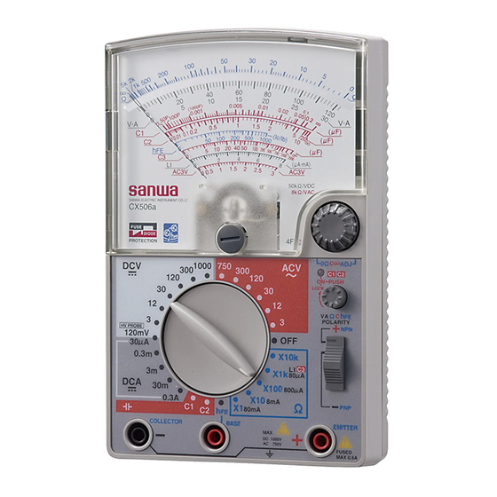
【2】用途と特長 2−1 用 途 本器は、小容量電路の測定用に設計された、携帯用アナログマル チテスタです。小型の通信機器や、家電製品、電灯線電圧や各種電 池の測定などはもちろん、コンデンサの静電容量測定やトランジス タチェッカとしてもご使用いただけます。 2−2 特 長 ●6ファンクション/ 26 レンジと豊富な機能 ●高感度トートバンドメータの採用で DCV は 50 kΩ/V と高入力抵抗 ●ワイドな静電容量測定機能付き(内蔵発振器、 抵抗レンジ使用) ●電源スイッチ固定機能により静電容量の連続測定が可能であり、 電源 ON 表示ランプで電源の ON、OFF が確認できる親切設計 ●+、−極性切り換えSW付き(DCVとDCAファンクション) ●簡易トランジスタチェック機能付き 【3】各部の名称 目盛板 (スケール板) メータ指針 0 Ω ・ C ∞調整器つまみ メータ0位調整器 ファンクション電源 ON表示ランプ ファンクション/レンジ 切り換えスイッチつまみ... -
Page 10: 4】指示の読み取り方
【4】指示の読み取り方 ① ② ③ ④ ⑤ ⑧ ⑥ ⑦ ⑨ 使用レンジ 読み取り倍率 使用レンジ 読み取り倍率 使用レンジ 読み取り倍率 ×1 × 10 k Ω×10 k ×10 DCV 300 ④ ×1 k ×1 Ω×1 k ×1 DCV 30 ⑤ ×100 ×1 Ω×100 ×0.1 DCV 3 ①... -
Page 11: 5】機能説明
【5】機能説明 5−1 スイッチ・調整器 ①ファンクション/レンジ切り換えスイッチ つまみを回すことによりファンクションおよびそのレンジを切 り換えることができます。 ②メータ0位調整器 この調整器を(−)ドライバーで回して、メータの指針を目盛 左端の0位に合わせます。 ③ 0 Ω・C∞調整器 抵抗(Ω) 、 静電容量(C1〜C3) 、 h 測定のときに使います。 測定前にテストピンをショートしてこのつまみを回し、Ω測定 とh 測定はΩ目盛の0に、C1〜C3測定の場合は各C目盛の∞に メータの指針を合わせます。 ④ ファンクション電源用押しボタンスイッチ 静電容量(C1、C2)を測定するときには、このボタンを操作 し、電源を ON の状態にして測定します。ボタンを指先で押す と、電源は ON、離すと OFF になります。ボタンを押しながら 右へ約45 °回すとボタンは沈んだまま固定され、電源は連続 ONの状態になります。測定終了後は電池の消耗を防ぐため、 必ずボタンを左に回して電源を OFF にします。 ⑤ ファンクション電源ON表示ランプ ファンクションの測定用電源がONのときに点滅します。 ⑥極性切り換えスイッチ... -
Page 12: 6】測定方法
【6】測定方法 6−1 始業点検(次ページのフローチャートを参照のこと) 警 告 1. 感電防止のため、テスタ本体またはテストリードが損傷して いる場合は使用しないこと。 2. テストリードまたはヒューズが切れていないことを確認する こと。 6−2 レンジの設定方法 ①電圧(DCV、ACV) 、電流(DCA)の最適なレンジの選択 原則として、最大目盛値が測定しようとする値より大きく、し かもメータがなるべく大きく振れるようなレンジを選びます。 例えば9 Vの電圧を測定する場合は 3 Vや300 Vレンジではなく 12 Vレンジを、 15 Vを測定する場合は30 Vレンジを選択します。 測定値の見当がつかない場合は、 最大のレンジ (DCVは1000 V、 ACVは750 V、DCAは0.3 A)で測定してみます。 ②抵抗(Ω)の最適レンジの選択 なるべく指示をΩ目盛の中央付近で読み取れるレンジを選択し ます。 6−3 測定前の準備 0位調整器を回し、 メータ指針を目盛板左端の0位置に合わせます。 スタンドの使い方 メータ0位調整 − 6 −... - Page 13 点検スタート 本体および 壊れている テストリードの 外観が壊れてい ますか? ※内蔵電池が完全に そのまま使用せず、 壊れていない 消耗していても指 修理を依頼してくだ 針は振れません。 テストリードおよび さい。 ヒューズの断線確認 ①黒プラグを−入力 ⑤赤、黒のテストピ ヒューズまたはテスト 端子に差し込みま ンをショートしま リードを交換してやり す。 す。 直してみても指針が振 れない場合は、修理を ②赤プラグを+入力 依頼してください。 端子に差し込みま す。 ⑥指針が ※ 振れていない 右に大きく振れ ③ファンクション/ ていますか? レンジ切り換えつ まみをΩ×10 kレン ヒューズまたはテス ジに合わせます。 トリードを交換して...
-
Page 14: 6−4 電圧(V)測定
6−4 電圧 (V) 測定 警 告 1. 各レンジの最大定格入力電圧を超えた入力を加えないこと。 2. 測定中は他のレンジやファンクションに切り換えないこと。 3. 測定値の見当がつかない場合は、最大レンジで測定すること。 4. 測定中はテストリードのつばよりテストピン側を持たないこと。 5. 負荷と並列に接続して測定すること。 6−4−1 直流電圧(DCV ) 最大測定電圧 DC 1000 V 1) 電池や直流回路の電圧を測ります。 2) 測定レンジ 120 m/3/12/30/120/300/1000までの7レンジ 3) 測定方法 ①極性切り換えスイッ ④ ⑤ チは通常+側です。 ⑥ ⑥ ②テストリードの赤プ ラグを+入力端子、 電池 黒プラグを−入力端 子に差し込みます。 ③ファンクション/レ ①... - Page 15 6−4−2 交流電圧 (ACV〜) 測定 最大測定電圧 AC 750 V 1) 測定対象 主に電灯線回路など、正弦波交流の電圧を測ります。 2) 測定レンジ 3/12/30/120/300/750までの6レンジ 3) 測定方法 ①極性切り換えスイッ ④ チは+側にします。 ⑥ ⑥ ②テストリードの赤プ ⑤ ラグを+入力端子に、 黒プラグを−入力端 コンセント 子に差し込みます。 ③ファンクション切り ① 換えつまみを回して ③ ACV〜の最適なレン ② ② ジに合わせます。 ④被測定回路の測定点 に負荷と並列になるよう、赤と黒のテストピンをそれぞれ 接続します。交流は+、−の極性には無関係です。 ⑤V・A目盛でメータの指示を読み取ります。 ただし、3 VレンジはAC 3 V目盛で読み取ります。 ⑥測定後は、被測定回路からテストピンをはずします。...
-
Page 16: 6−5 直流電流(Dca )測定
6−5 直流電流 (DCA ) 測定 最大測定電流 DC 0.3 A 警 告 1. 人体への危険や本器の故障防止上、入力端子に電圧を加えな いこと。 ○正しい接続 (直列) × 危険な接続 (並列) 2. 必ず負荷を通して直列に 接続すること。 (右図参照) 電源 電源 負荷 負荷 3. 入力端子に最大定格電流 を超える電流を流さない こと。 1) 測定対象 電池や直流回路の電流を測ります。 2) 測定レンジ ⑤ 30μ/0.3 m/3 m/30 m /0.3(5レンジ) 抵抗器 電池 3)... -
Page 17: 6−6 抵抗(Ω)測定
6−6 抵抗 (Ω) 測定 最大測定抵抗 50 MΩ 警 告 電圧の加わっている部分の抵抗測定をすると、本器の故障の原 因となるばかりではなく、人体へ危険が及ぶことがあります。 1)測定対象 抵抗器や回路の抵抗測定、部品や回路の導通チェックをします。 2)測定レンジ ×1/×10/×100/×1 k/×10 kΩ (5レンジ) 3)測定方法 ⑥ ①極性切り換えスイッ ④ チは+側へセットし ます。 ⑦ ⑦ ②テストリードの赤プ 抵抗器 ラ グ を + 入 力 端 子 ⑤ に、黒プラグを−入 ① 力端子に差し込みま す。 ③ ③ファンクション切り ② ②... - Page 18 ●LED の発光テスト 本器の Ωレンジは3 Vで動作させていますので、LED の発光 テストが行えます。適当なレンジは×10レンジです。 ●抵抗レンジの+、−測定端子の極性 本器パネル上の測定端子に付記されている+、−とは逆極 性となります(+測定端子に内蔵電池の−が接続される) 。 ●ダイオード、トランジスタなど半導体の抵抗測定上の注意 ・測定電圧の加わる方向で、その値が大きく変わります。 前項の入力端子の極性に注意してください。 ・使用するレンジ(×1/×10…)により抵抗値が変わりま す。被測定物に流れる電流が使用するレンジにより変わ るためです。 ●端子開放電圧 ×1〜×1 kレンジ:約 3 V ×10 kレンジ:約12 V ●人体の抵抗による影響 テストピンに指を触れて測定すると、人体の抵抗の影響を 受けて誤差を生じます。 特に、×1 kレンジと×10 kレンジでその影響が大きくなり ます。 ●内蔵ヒューズの抵抗の影響 仕様の項目に記された定格「500 mA/250 V φ5×20セラミ ック管入り速断ヒューズ」と異なるヒューズを使用すると、 その抵抗値の違いにより、×1レンジで 0 Ω調整ができなく なったり誤差を生じたりすることがあります。必ず同定格...
-
Page 19: 6−7 静電容量( )測定
6−7 静電容量 ( ) 測定 警 告 電圧の加わっているコンデンサの測定はしないこと。 このレンジに電圧が加わると、本器の故障の原因となるばかり ではなく、人体へ危険が及ぶことがあります。 6−7−1 C1、C2レンジでの測定(内蔵発振器を使用) :測定範囲50 pF〜20μF 1) 測定対象 主にコンデンサの静電容量を測ります。 2) 測定レンジ C1レンジ…50 pF〜0.2μF C2レンジ…0.01〜20μF 3) 測定方法 ⑦ ①極性切り換えスイッ ⑤ チは+側にします。 ②テストリードの赤プ ラグを+入力端子に、 ④ 黒プラグを−入力端 コンデンサ 子に差し込みます。 ⑧ ⑧ ⑨ ③ファンクション切り ① 換えつまみを C1(ま ⑥ たは C2)レンジに合 ③... - Page 20 ●充電されているコンデンサを測定するときには、測定前に コンデンサの端子間をショートし電荷を放電させてください。 充電された状態で測定すると本器を破損する恐れがあります。 ●有極性コンデンサの測定ではコンデンサの+側が本器の+ 入力端子側となるように接続してください。 ●周波数が数 10 kHz 以上の強力な電磁界のある環境下では誤動作 をすることがあります。 参 考 ・測定周波数 C1レンジ:約 900 Hz C2レンジ:約 800 Hz ・測定電圧 使用するレンジ、測定する静電容量の大きさにより測定 電圧が変化します。例えば…… C1レンジ :200 pF測定時/約8.0 V(peak) :0.05μF測定時/約0.5 V(peak) C2 レンジ:0.1μF測定時/約4.0 V(peak) :5.0μF測定時/約0.7 V(peak) ●コードの断線有無チェックへの応用(C1レンジ使用) コードには長さに比例した静電容量があります。 コード芯線間の静電容量を標準となる同一長さのコードと 比較測定することで、断線有無のチェックができます。 Cx 1 断線箇所 Cx 2 Cx 1>Cx 2 標準となるコードと比べて静電容量が著しく小さければ、...
-
Page 21: 6−7−2 C3レンジでの測定
6−7−2 C3レンジでの測定 (Ω×1 k レンジを使用) 測定範囲1〜2000μF 1) 測定対象 電解コンデンサなど比較的大容量コンデンサの概略値を測り ます。 ⑥ 2) 測定レンジ C3 レンジ 3) 測定方法 ①極性切り換えスイッ チは+側にします。 ②テストリードの赤プ ⑤ ラ グ を + 入 力 端 子 に、黒プラグを−入 ⑥ コンデンサ 力端子に差し込みま ⑦ ⑦ す。 ③ファンクション切り ① 換えつまみをC3レン ③ ジ(Ω×1 kレンジと ④導線... -
Page 22: 6−8 トランジスタの測定
6−8 トランジスタの測定 警 告 入力端子には外部から電圧を絶対に加えないこと。 本器の故障の原因となるばかりではなく、人体へ危険が及ぶこ とがあります。 6−8−1 I (漏洩電流) の測定 1) 測定対象 トランジスタの I (コレクタ、エミッタ間のもれ電流)を測り ます。 (NPN トランジスタ測定の場合) 2) 測定レンジ E…エミッタ レンジ B…ベース 3) 測定方法 C…コレクタ ①テストリードの赤プ ⑥ ラ グ を + 入 力 端 子 ④ (EMITTER) に、黒プ ラ グ を − 入 力 端 子 (COLLECTOR)に差... -
Page 23: 6−8−2 直流電流増幅率(H Fe )の測定
6−8−2 直流電流増幅率 (h ) の測定 1) 測定対象 トランジスタの直流電流増幅率(h ) の概略値を測ります。 2) 測定レンジ レンジ (NPN トランジスタ測定の場合) 3) 測定方法 E…エミッタ ①テストリードの赤プ B…ベース ラ グ を + 入 力 端 子 C…コレクタ (EMITTER) に、黒プ ⑧ ラ グ を − 入 力 端 子 ⑤ (COLLECTOR)に差... -
Page 24: 6−9 高圧プローブ (Hv-60) による直流高電圧 (Hv) の測定 (別売品
6−9 高圧プローブ (HV-60) による直流高電圧 (HV) の測定 (別売品) 最大測定電圧 DC 30 kV 警 告 1. HV-60は微小電流回路の直流高電圧測定用プローブです。 送電線などの強電回路の測定には使用しないこと。 2. 最大測定電圧(DC 30 kV)を超える電圧を測定しないこと。 3. 測定中はプローブのつばよりピン先側を持たないこと。 4. 測定中はファンクション切り換えつまみを切り換えないこと。 1) 測定対象 テレビのブラウン管アノード電圧など、高インピーダンス回路 (微小電流回路)の直流高電圧を測ります。 2) 測定レンジ HV PROBE (DC 120 mV)レンジ ⑤ ブラウン管 3) 測定方法 ④アノード ①極性切り換えスイッ ⑥ チを+側にセットし... -
Page 25: 7】保守管理について
【7】保守管理について 警 告 1. この項目は安全上重要です。 本説明書をよく理解したうえで管理を行ってください。 2. 安全と確度の維持のために 1年に 1回以上は校正、点検を行って ください。 7−1 保守点検 1) 外観 ●落下などにより外観(パネル、リヤケースなど) が破損し ていないか? 2) テストリードと内蔵ヒューズ ●入力端子にプラグを差し込んだときに緩みはないか? ●テストリードのどこかに芯線など、金属部分の露出してい る箇所はないか? ●テストリードおよびヒューズが切れていないかどうかは、7 ペ ージの点検用フローチャートにて確認してください。 以上の点検で破損や、断線を見つけた場合は、そのままの状態で 使用せずに、製造元へ修理依頼するか新品と交換してください。 7−2 校正点検 校正、点検は製造元でも行っています(有料) 。 詳細は三和電気計器 (株) ・羽村工場サービス課(22ページ [送り先] の項を参照)へお問い合わせください。 7−3 内蔵電池・ヒューズの交換 警 告 1. 入力端子に電圧が加わった状態でリヤケースをはずすと、感 電のおそれがあります。必ず、電圧の加わっていないことを 確認してから作業を行うこと。 2. - Page 26 内蔵電池の交換方法 ①リヤケース取り付けネジを緩めてリヤケースをパネルからは ずし、更に、消耗した 1.5 V電池(R6型)2 本または 9 V電池 (6F22型)1本をはずします。 ②新品の電池を電池ホルダへ+、−の極性を間違わないように、 確実にはめ込みます (1.5 V電池は新旧電池を混用しないこと) 。 ★電池ホルダーへ電池を逆極性に入れるとヒューズがしゃ断します。 ③パネルとリヤケースをしっかりとはめ合わせネジ止めします。 内蔵ヒューズの交換方法 予備ヒューズ ΩやDCAファンクショ 単3型電池 ンに誤って電圧 (100 V 積層電池 (9 V) (1.5 V) の 電 灯 線 電 圧 な ど ) を 加えますと、安全のた め内蔵ヒューズがしゃ 断します。ヒューズが...
-
Page 27: 7−4 清掃と保管について
7−4 清掃と保管について 注 意 1. パネル、リヤケース、メータカバーは揮発性溶剤(シンナー やアルコールなど)で変質することがあります。 汚れは柔らかい布で、乾拭きをするか少量の水を含ませて拭 き取ってください。 2. パネル、リヤケース、メータカバーなどは熱に弱いため、はん だごてなど熱を発生するものの近くに置かないでください。 3. 振動の多い場所、落下のおそれのある場所に保管しないでく ださい。 4. 直射日光下、高温(炎天下の自動車内など)または低温、多 湿、結露のおそれのある場所での保管は避けてください。 5. 長期未使用の場合は必ず内蔵電池を抜いて保管してください。 【9 以上の注意項目を守り、環境の良い場所 ( 】9-1項参照) に保管 してください。 【8】アフターサービス 8−1 保証期間について 本製品の保証期間は、お買い上げの日より 3 年間です。 ただし、日本国内で購入し日本国内でご使用いただく場合に限り、 また、許容差は 1 年保証、製品付属の電池、ヒューズ、テストリー ド等は保証対象外とさせていただきます。 8−2 修理について 1) 修理依頼の前に次の項目をご確認ください。 ●内蔵電池が消耗していませんか? 装着の極性は正しいで すか?... -
Page 28: 8−3 お問い合わせ
金額は 2014 年 4 月現在のもので消費税を含みます。 8−3 お問い合わせ 三和電気計器株式会社 :TEL(03) 3253 — 4871 / FAX(03) 3251 — 7022 本社 :TEL(06) 6631 — 7361 / FAX(06) 6644 — 3249 大阪営業所 ホームページ :http://www.sanwa-meter.co.jp 製品についての問い合わせ: 0120-51-3930 受付時間 9:30 〜 12:00 13:00 〜 17:00 (土日祭日および弊社休日を除く) 説明書中の仕様や内容については予告なしに変更、中止するこ とがございますのでご了承ください。... -
Page 29: 9】仕 様
:165 ( H ) ×106 ( W ) ×46 ( D ) ・約370 g 寸法・質量 付属品 :取扱説明書 1、テストリード TL-21a 1 :クリップ付きリード CL-506a :1 :予備ヒューズ0.5 A/250 V :1 ( 本体に内蔵) 9−2 別売付属品 ●携帯ケース(C-CA) ●高圧プローブ(HV-60) 測定範囲:DC 0〜30 kV 内部抵抗:1000 MΩ 本器(CX506a)との組み合わせ許容差:±20 % − 23 −... -
Page 30: 9−3 測定範囲および許容差
9−3 測定範囲および許容差 許容差保証温湿度範囲:23±2 ℃、75 %RH以下、結露の無いこと 姿勢 (本器の置かれている状態) :水平に対して±5 °以内 ACVレンジは正弦波交流50/60 Hzで規定 ファンクション 測定レンジ (最大目盛値) 許 容 差 備 考 120 m 最大目盛値の ±4 %以内 内部抵抗 4 kΩ 直流電圧 3/12/30/120/ 内部抵抗 50 kΩ/V 最大目盛値の (DCV ) 1000 Vレンジ 15 kΩ/V ±2.5 %以内 300/1000 最大目盛値の 交流電圧 3/12/30/120/ ±3 %以内... -
Page 31: Safety Precautions:before Use, Read The Following Safety Precautions
Before use, read the following safety precautions This instruction manual explains how to use your multitester CX506a, safely. Before use, please read this manual thoroughly. After reading it, keep it together with the product for reference to it when necessary. -
Page 32: Explanation Of Warning Symbols
1-2 Explanation of Warning Symbols The meanings of the symbols used in this manual and attached to the product are as follows. : Very important instruction for safe use. ・The warning messages are intended to prevent accidents to operating personnel such as burn and electrical shock. ・The caution messages are intended to prevent damage to the instrument. -
Page 33: Application And Features
[2] APPLICATION AND FEATURES 2-1 Applications T h i s i n s t r u m e n t i s p o r t a b l e m u l t i m e t e r d e s i g n a t e d f o r measurement of weak current circuit. -
Page 34: Scale Reading
[4] SCALE READING ① ① ④ ③ ⑤ ⑧ ⑥ ⑦ ⑨ Range Multiplier Range Multiplier Range Multiplier Ω X 10 k X 10 k DCV 300 X 10 ④ Ω X 1 k X 1 k DCV 30 ⑤ Ω... -
Page 35: Description Of Functions
[5] DESCRIPTION OF FUNCTIONS 5-1 Selectors, adjusters and switches ①Function/Range selector Turn the instrument on by selecting any measurement range. ②Meter zero position adjuster Turn the adjuster to have the pointer align with the zero line. (scale left edge) ③0 Ω・C∞Adjuster For resistance or hFE measurement, turn the adjuster to have the pointer align with the zero line (0 Ω) while test leads are shorted. -
Page 36: Measurement Procedure
[6] MEASUREMENT PROCEDURE 6-1 Start-Up Inspection WARNING 1. Never use meter if the meter or test leads are damaged or broken. 2. Make sure that the test leads are not cut or otherwise damaged. 6-2 How to select an appropriate range (Selection of a appropriate range) ①For voltage or current measurements, select a function/range selector is higher than the value to be measured. - Page 37 START Main unit Damaged and test leads damaged ? No damaged Stop using it and have it repaired. Check continuity of test leads and fuse. Connect the black plug Stop using it and Short the red and have it repaired. of the test lead to the black test pins.
-
Page 38: Voltage Measurement
6-4 Voltage Measurement WARNING 1.Never apply an input signals exceeding the maximum rating input value. 2.Be sure to disconnect the test pins from the circuit when changing the function / range. 3.Select the maximum range and measure, if the value to be measured is uncertain. -
Page 39: Acv Measurement ( ) ・・・・・・・・・・・・・・・・・・・・・・・・・・・・・・・・・・・・ 0
6-4-2 ACV Measurement ( ): Max.measurement value 750 VAC 1) Application Measures sine-wave AC voltages such as lighting voltages. 2) Measuring range: 3/12/30/120/300/750 (6ranges) ④ ⑥ ⑥ ⑤ Outlet ① ③ ② ② 3) Measurement procedure Shift the polarity reversal switch to + side. ①... -
Page 40: Dca Measurement
6-5 DCA Measurement ( ): Max. measuremet value 0.3 ADC WARNING 1. Never apply voltage to × Incorrect ○ Correct the input terminals. 2. Be sure to make a series connection via load. Power Power Load Load 3. Do not apply an input exceeding the maximum rated current to the input terminals. -
Page 41: Resistance Measurement
6-6 Resistance Measurement Max. measurement value 50 M WARNING Never apply voltage to the input terminals. 6-6-1 Resistance Measurement ( Ω ) 1) Application Resistance of resistors or circuits are measured. 2) Measuring range: X1/X10/X100/X1 k/X10 k (5ranges) 3) Measurement procedure Shift the polarity reversal switch to +... -
Page 42: Terminal To Terminal Current (Li)
6-6-2 Terminal to Terminal Current (LI) Terminal-to-Terminal Current is the current that runs between − and + terminals when measuring resistance. There may be some cases that the impedance of measured object varies, especially when measuring semi-conductors, due to self- heating caused by current running while measuring resistance. -
Page 43: Capacitance Measurement ( ) ・・・・・・・・・・・・・・・・・・・・・・・・・・・・・・ 0
6-7 Capacitance Measurement ( WARNING 1.Never apply voltage to the input terminals. 2.Discharge the capacitance before measuring it. 6-7-1 C1,C2 ranges 1) Application Measurement of capacitance 2) Measuring range C1 range : 50 pF〜0.2 µF C2 range : 0.01〜20 µF 3) Measurement procedure Shift the polarity reversal switch to +... - Page 44 Note Measuring frequency ① C1range : approx. 900 Hz C2range : approx. 800 Hz Measuring voltage ② C1range : approx.8.0 V (peak)/When 200 pF is measured C1range : approx.0.5 V (peak)/When 0.05 µF is measured C2range : approx.4.0 V (peak)/When 0.1 µF is measured C2range : approx.0.7 V (peak)/When 5.0 µF is measured Application ③...
-
Page 45: C3 Range
6-7-2 C3 range 1) Application Measured large capacitor 2) Measuring range: C3 range: 1〜2000 µF 3) Measurement procedure Shift the polarity reversal switch to + side. ① Connect the black plug of the test lead to the − input terminal ②... -
Page 46: Transistor Measurement
6-8 Transistor Measurement WARNING Never apply voltage to the input terminals. 6-8-1 I Measurement 1) Application Measuring Iceo of transistor 2) Measuring range: h range 3) Measurement procedure Connect the black plug of the test lead to the − input terminal ①... -
Page 47: Fe Measurement
6-8-2 h Measurement 1) Application Measuring h of transistor 2) Measuring range: h range 3) Measurement procedure Connect the black plug of the test lead to the COLLECTOR ① (−input) terminal and the red plug to the EMITTER (+ input) terminal. Connect the black plug of the clip lead to the BASE terminal. -
Page 48: Dc High Voltage Measurement
6-9 DC High Voltage measurement (HV) (Optional HV Probe) Max. measurement value 30 kV DC WARNING 1.The probe is designed for the measurement of very small direct current circuit. Never use the probe to measure high voltage in power lines, such as transmission and distribution lines;... -
Page 49: Maintenance
[7] MAINTENANCE WARNING 1.This section is very important for safety. Read and understand the following instruction fully and maintain your instrument properly. 2. The instrument must be calibrated and inspected at least once a year to maintain the safety and accuracy. 7-1 Maintenance and inspection 1) Appearance Is the appearance not damaged by falling ? - Page 50 How to replace the battery or fuse> < Remove the rear case screw with a screwdriver. ① Remove the rear case. ② Take out the battery or fuse and replace it with a new one. ③ Attach the rear case and fix it with the screw. ④...
-
Page 51: Cleaning And Storage
Sanwa authorized agent or distributor. Sanwa reserves the right to inspect all warranty claims to determine the extent to which the warranty policy shall apply. This warranty shall not apply to fuses, test leads, disposables batteries, or any product or parts, which have been subject to one of the following causes: 1. -
Page 52: Repair
3) Repair after the warranty period has expired: In some cases, repair and transportation cost may become higher than the price of the product. Please contact Sanwa authorized agent / service provider in advance. The minimum retention period of service functional parts is 6 years after the discontinuation of manufacture. -
Page 53: Specifications
[9] SPECIFICATIONS 9-1 General Specification AC Rectifier form : Half-wave rectifier form Meter type : Internal magnet, Taut band meter (15 µA) Accuracy assurance Temperature/Humidity range : 23±2 ℃ 75 %RH max. No condensation Operating temperature and humidity : 5〜31 ℃,80 %RH max. 〜40 ℃, 80〜50 %RH (decreasing linearly) <... -
Page 54: Optional Accessories
9-2 Optional Accessories ・Clip adapter CL-14 (Red, Black 1set) ・HV probe HV-60 (DC 0〜30 kV Internal resistance:1000 MΩ) ・Carrying case C-CA 9-3 Measurement Range and Accuracy Accuracy assurance range : 23±2 ℃ 75 %RH max. No condensation : Horizontal (±5 ° ) Attitude ACV accuracy in the case of sine wave AC. - Page 55 Specifications and external appearance of the product described above may be revised for modification without prior notice. — 49 —...
- Page 56 MEMO...
- Page 57 保証書 CX506a ご氏名 型 名 様 製造No. ご住所 この 製 品 は 厳 密なる品 質 管 理 を 経て お届けするものです。 本保証書は所定項目をご記入の上保管 していただき、アフターサービスの際 ご提出ください。 ※本保証書は再発行はいたしませんので 大切に保管してください。 保証期間 ご購入日 年 月より 3 年間 本社=東京都千代田区外神田2−4−4 ・ 電波ビル (製品の許容差については 1 年間) 郵便番号=101-0021・電話=東京 (03) 3253−4871 ( 代)...
- Page 60 本社=東京都千代田区外神田 2−4−4・電波ビル 郵便番号=101-0021・電話=東京 (03) 3253−4871 (代) 大阪営業所=大 阪市浪速区恵美須西2 −7 −2 郵便番号=556-0003・ 電話 = 大阪 (06) 6631−7361 ( 代) Dempa Bldg., 4-4 Sotokanda 2-Chome, Chiyoda-Ku, Tokyo, Japan 植物油インキを使用しています。 15-1802 2040 2040...
Need help?
Do you have a question about the CX506a and is the answer not in the manual?
Questions and answers