Table of Contents
Advertisement
Quick Links
Advertisement
Table of Contents

Related Manuals for Sanwa EM7000


Summary of Contents for Sanwa EM7000
- Page 1 EM7000 FET電子テスタ FET MULTITESTER 取扱説明書 INSTRUCTION MANUAL...
-
Page 3: Table Of Contents
目 次 【1】 安全に関する項目~ご使用前に必ずお読みください~ …… 1 1-1 安全使用のための警告文および注意文 ………………… 1 1-2 警告マークなどの記号説明 ……………………………… 2 1-3 最大過負荷保護入力値 …………………………………… 2 【2】用途と特長 ……………………………………………………… 3 2-1 用 途 ……………………………………………………… 3 2-2 特 長 ……………………………………………………… 3 【3】各部の名称 ……………………………………………………… 3 【4】指示の読み取り方 ……………………………………………… 4 【5】機能説明 ………………………………………………………… 5 5-1 スイッチ・調整器 ………………………………………… 5 5-2 スタンドの使い方 ………………………………………… 5 5-3 電池交換の時期 …………………………………………… 5 【6】測定方法 ………………………………………………………… 6 6-1 始業点検 …………………………………………………… 6 6-2 レンジの選択方法 ………………………………………… 6 6-3 測定前の準備 ……………………………………………… 6 6-4 電圧測定 …………………………………………………… 8 6-4-1 直流電圧(DCV ) ……………………………… 8 6-4-2 ±直流電圧(±DCV ... - Page 4 6-9 測定の終了 ………………………………………………… 19 【7】保守管理について ……………………………………………… 20 7-1 保守点検 …………………………………………………… 20 7-2 校正点検 …………………………………………………… 20 7-3 内蔵電池・ヒューズの交換 ……………………………… 20 7-4 清掃と保管について ……………………………………… 22 【8】アフターサービス ……………………………………………… 22 8-1 保証期間について ………………………………………… 22 8-2 修理について ……………………………………………… 22 8-3 お問い合わせ ……………………………………………… 23 【9】仕 様 …………………………………………………………… 24 9-1 一般仕様 …………………………………………………… 24 9-2 別売付属品 ………………………………………………… 24 9-3 測定範囲および許容差 …………………………………… 25 保証書...
-
Page 5: 1】 安全に関する項目~ご使用前に必ずお読みください
【1】 安全に関する項目~ご使用前に必ずお読みください~ このたびはFET電子テスタEM7000型をお買い上げいただき誠にあ りがとうございま す。 ご使用前にはこの説明書をよくお読みいただき、正しく安全にご使 用ください。 また紛失しないよう製品と一緒にして保管してください。 本文中の“ 警告”および“ 注意”の記載事項は、やけどや感 電などの人身事故、本器の故障や誤動作防止上必ずお読みください。 1-1 安全使用のための警告文および注意文 警 告 以下の項目は、やけどや感電など人身事故を防止するためのもの です。本器をご使用する際には必ずお守りください。 なお、取扱説明書での説明以外の使い方をしますと、本器に与えら れた保護が損なわれることがありますのでご注意ください。 01. 6 kVAを超える電力ラインでは使用しないこと。 02. AC 33 Vrms (46.7 Vpeak) 、DC 70 V以上の電圧は人体に危険なた め注意すること。 03. 最大定格入力値を超える信号は入力しないこと。 04. 最大過負荷入力値を超えるおそれがあるため、誘起電圧、サー ジ電圧の発生する (モータ等) ラインの測定はしないこと。 05. 本体やテストリードが損傷している場合は使用しないこと。... -
Page 6: 1-2 警告マークなどの記号説明
1-2 警告マークなどの記号説明 本器および『取扱説明書』に使用されている記号と意味について :安全に使用するための特に重要な事項を示し、たとえば… 警 告:やけどや感電など人身事故を防止するための警告 です。 注 意:本器を取り扱ううえで、破損や誤動作を防止する ための注意です。 :直流 (DC) Ω:抵抗 +:プラス -:マイナス ~:交流 (AC) :高電圧注意 :グランド p-p :尖頭値間 (peak to peak) ∞:無限大 :ヒューズとダイオードによる回路保護 :ヒューズ :二重絶縁または強化絶縁 :センタ “0” メータ 1-3 最大過負荷保護入力値(容量6kVA以内の電路について) ファンクション(レンジ) 入力端子 最大過負荷保護入力値 *1 1000 DC・AC 1000 V または peak max 1400 V 1.2/3/12/30 DC・AC 240 V または... -
Page 7: 2】用途と特長
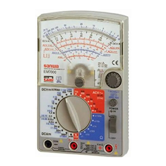
【2】用途と特長 2-1 用 途 本器は小容量の電路の測定用に設計された高感度のテスタです。 小型の通信機器や家電製品の各部の電圧、 電灯線や各種電池の電圧、 繰り返し電圧波形のP-P値、 μA級の微小電流などの測定ができます。 2-2 特 長 ● 本器は直流電圧ファンクションが2.5~12 MΩと高内部抵抗で あり、直流電流ファンクションも0.12μAレンジ付きと高感度 な“FET電子テスタ”です。 ● 中心零メータ(NULLメータ)機能により±直流電圧、±直流 電流の測定に便利です。 ● 交流低電圧レンジの周波数特性は正弦波交流に於いて40 Hz~1 MHzと良好です。3 Vレンジではデューティー比20 %以上の方 形波状パルスのP-P値(Peak to Peak値)測定が可能です。 ● 最小0.2 Ω~最大200 MΩと広範囲の抵抗測定ができます。 【3】各部の名称 メーターカバー 目盛板 (スケール板) 0 Ω調整器 (0 Ω ADJ) メータ指針... -
Page 8: 4】指示の読み取り方
【4】指示の読み取り方 ① ② 狠 獏 ③ ④ ⑥ ⑤ ⑧ ⑦ ⑨ 目盛 使用レンジ 読み取り倍率 目盛 使用レンジ 読み取り倍率 目盛 使用レンジ 読み取り倍率 Ω×100 k ×100 k ACV 300 ×10 ACV (P-P) 330 ×10 ⑤ * Ω×10 k ×10 k ACV 30 ×1 ACV (P-P) 33 ×1... -
Page 9: 5】機能説明
【5】機能説明 5-1 スイッチ・調整器 ①ファンクション/レンジ切り換えスイッチ つまみを回すことにより目的のファンクションおよびレンジを 選択することができます。 ②機械的メータ0位調整器 この調整器をマイナスねじ回し(ドライバ)で回して、メータ の機械的な0位を合せます(6ページ下方の図) 。このとき、電 源スイッチは必ず切った(OFF)状態で行います。 ③電源スイッチ(POWERスイッチ)および電源ON表示ランプ つまみを上方向(ON方向)にスライドすると電源が入り電源 ON表示ランプが点滅し、本器が動作状態になったことを示し ます。つまみを手前方向(OFF方向)にスライドすると電源が 切れて、電源ON表示ランプは消灯します。 内蔵電池が消耗しますので、使用後は必ず電源スイッチを OFF側に切り換えてください。 ④電気的メータ0位調整器 (ZERO ADJ) :6F22型 (積層型9 V) で動作 機械的メータ0位調整の後に電源スイッチを入れてから操作します。 ・±直流電圧(±DCV)および±直流電流(±DCA)の測定 では、電源スイッチ入れた後このつまみを回し、指示(指針) を±DCV・A 目盛中央の0目盛線に合せます。 ・上記を除く ファンクションの測定では、電源スイ ッチを入れた後 このつまみを回して指示をDCV ・ A目盛の0目盛線に合せます。 ⑤0 Ω調整器(0 Ω ADJ) :R6P型(単3型1.5 V)で動作 抵抗値測定時に使用します。測定前に電源スイッチを入れ、テ... -
Page 10: 6】測定方法
【6】測定方法 6-1 始業点検(次ページのフローチャートを参照のこと) 警 告 1. 感電防止のため、テスタ本体またはテストリードが損傷して いる場合は使用しないこと。 2. テストリードまたはヒューズが切れていないことを確認すること。 6-2 レンジの選択方法 ①電圧 (DCV、 ±DCV、 ACV (rms) 、 ACV (P-P) ) 、電流 (DCA、 ±DCA) 原則として最大目盛値が測定しようとする値よりも大きく、しか もメータの指針がなるべく大きく振れるようなレンジを選びます。 例えば、DC 9 Vの電圧を測定する場合の測定レンジは3 Vレンジや 30 Vレンジではなく12 Vレンジを、DC 15 Vを測定する場合は30 V レンジを選択します。 ②抵抗(Ω) なるべくΩ目盛の中央付近を指示するようなレンジを選択します。 6-3 測定前の準備 ①メータの指針が目盛板左端の0目盛を正しく指示していない場合... - Page 11 点検スタート 本体および 壊れている テストリードの外観が 壊れていませんか? ※内蔵電池が完全に そのまま使用せず、 壊れていない 消耗している場合 修 理 依 頼 し て く だ も、指針は振れま テストリードおよび さい。 せん。 ヒューズの断線確認 ①黒プラグを-入力 ⑤赤、黒のテストピ ヒューズまたはテスト 端子に差し込みま ンをショートしま リードを交換してやり す。 す。 直してみても、指針が 振れない場合は修理依 ②赤プラグを+入力 頼してください。 端子に差し込みま す。 ⑥指針が * 振れない 右へ大きく振れ ③ファンクション/レ...
-
Page 12: 6-4 電圧測定
6-4 電圧測定 警 告 1. 各レンジの最大定格を超えた入力を加えないこと。 2. 測定中は他のファンクションやレンジに切り換えないこと。 3. 測定値の見当がつかない場合には最大の測定レンジで測定すること。 4. 測定中はテストリードのつばよりテストピン側を持たないこと。 5. 必ず負荷と並列接続して測定すること。 6-4-1 直流電圧 (DCV ) 最大測定電圧 DC 1000 V 1)測定対象 電池や直流回路の電圧を測ります。 2)測定レンジ 0.3/1.2/3/12/30/120/300/1000 V 以上の8レンジ 3) 測定方法 ⑤ ⑥ ①テストリードの赤プラ ⑦ ⑦ グを+入力端子、黒 ④ プラグを-COM入力 電池 子端に差し込みます。 ②ファ ンクシ ョ ン /レンジ ③... -
Page 13: 6-4-2 ±直流電圧(±Dcv
6-4-2 ±直流電圧 (±DCV ) 最大測定電圧 ±DC 600 V 1)測定対象 IC回路など基準に対し正負が混在した直流回路の電圧を測り ます。 2)測定レンジ ± 0.15/± 0.6/± 1.5/± 6/± 15/± 60/± 150/± 600 V 8レンジ 3) 測定方法 ①テストリードの赤プラ ⑥ グを+入力端子、黒 ⑦ プラグを-COM入力 ⑤ ④ + 子端に差し込みます。 Rf100k ②フ ァ ン クシ ョ ン切り換え -... -
Page 14: 6-4-3 交流電圧(Acv ~ Rms
6-4-3 交流電圧 (ACV~rms) 最大測定電圧 AC 750 V 1)測定対象 電灯線回路など正弦波交流の電圧を実効値 (rms) で測ります。 2)測定レンジ 3/12/30/120/300/750 V以上の6レンジ 3)測定方法 ⑤ ①テストリードの赤プラ ⑥ ⑦ ⑦ グを+入力端子、黒 プラグを-COM入力 ④ 子端に差し込みます。 ②ファンクション切り コンセント ③ 換えつまみを回して ⑧ ACV~rmsの最適レ ンジに合せます。 ② ③電源スイッチを入れ ① ① ます(POWER-ON: ランプが点滅する) 。 ④電気的メータ0位調整器(ZERO ADJ)つまみを回してメー タ指針を赤色のACV(rms)目盛の0目盛線に合せます。 ⑤測定2点間に赤黒それぞれのテストピンを接触させます... -
Page 15: 6-4-4 交流電圧(Acv ~ P-P
6-4-4 交流電圧 (ACV~ ) 最大測定電圧 AC 840 V 1)測定対象 正弦波交流の他、歪波交流(正弦波交流以外の交流、 8.4 Vレ ンジのみ)の最大値、最小値間の電圧(P-P値)を測ります (9-3項参照) 。 2)測定レンジ ⑤ ⑥ 8.4/33/84/330/840 V ⑦ ⑦ 以上の5レンジ ④ 3)測定方法 ①テストリードの赤プラ グを+入力端子、黒 コンセント ③ プラグを-COM入力 ⑧ 子端に差し込みます。 ② ②ファンクション切り ① ① 換えつまみを回して ACV~ ( ) の最適レ ンジに合せます。... -
Page 16: 6-5 低周波出力(Db)測定
6-5 低周波出力 (dB) 測定 1)測定対象 増幅器 (アンプ) の音声出力など、低周波の信号を測定します。 2)測定レンジ 11 dB(加算表付き:目盛板右下) 3)測定方法 ⑥ ①テストリードの赤プラ グを+入力端子、黒 ⑦ ④ ⑤ ⑧ プラグを-COM入力 RANGE ③ 子端に差し込みます。 ⑧ ⑤ ③ ②フ ァ ン ク シ ョ ン切り換え 11dB ⑨ つまみを回してACV~ ② (rms)の最適レンジ、 例えば3 Vレ ン ジ (11 dB) ①... -
Page 17: 6-6 電流測定
6-6 直流電流 警 告 1. 人体への危険や本器故障防止上、入力端子に電圧を加えないこと。 2. 必ず負荷を通して直列に接続すること。 3. 入力端子に最大定格電流 ○正しい接続 (直列) ×危険な接続 (並列) を超える電流を流さない こと。 電源 電源 負荷 負荷 4. 被測定回路の電源を切っ てから電流レンジを接続 すること。 6-6-1 直流電流 (DCA ) 最大測定電流 DC 300 mA 1) 測定対象 電池や直流回路の電流を測ります。 2) 測定レンジ ⑥ 0.12μ/0.3 m/3m/30m/ ④ 300 mA 以上の5レンジ 抵抗器... -
Page 18: 6-6-2 ±直流電流(±Dca
6-6-2 ±直流電流 (±DCA ) 最大測定電流 ±DC 150 mA 1)測定対象 検出回路など電流方向±が一定しない回路での測定に便利です。 2)測定レンジ ± 0.06μ/± 0.15 m/± 1.5 m/± 15 m/± 150 mA 以上の5レンジ 3) 測定方法 ①テストリードの赤プラ ⑥ グを+入力端子、黒 プラグを-COM入力 ④ 抵抗器 電池 子端に差し込みます。 (負荷) ②フ ァ ン ク シ ョ ン切り換え ⑦ ⑦... -
Page 19: 6-6-3 直流電流 (Dc 6 A
6-6-3 直流電流 (DC 6 A) 1)測定対象 小型電源回路などの6 A以下の直流電流を測ります。 2) 測定方法 ①テストリードの赤プラグをDC 6 A+/AC 6 A~入力端子 に、黒プラグを-COM入力子端に差し込みます。 ②ファンクション切り ⑥ 換えつまみを回し下 電源 方中央のDC 6 Aレ ④ 負荷 ンジに合せます。 ⑤ ⑦ ⑦ ③本器の電源スイッチを 入れます (POWER- ③ ON:ランプが点滅す ⑧ る) 。 DC6A ② ④電気的メータ0位調 ①... -
Page 20: 6-6-4 交流電流 (Ac 6 A
6-6-4 交流電流 (AC 6 A) 1)測定対象 小型電源回路などの6 A以下の交流電流を測ります。 2) 測定方法 ①テストリードの赤プラグをDC 6 A+/AC 6 A~入力端子 に、黒プラグを-COM入力子端に差し込みます。 ②ファンクション切り ⑥ 換えつまみを回し下 電源 方中央のAC 6 Aレン ④ 負荷 ジに合せます。 ⑤ ⑦ ⑦ ③本器の電源スイッチを 入れます (POWER- ③ ON:ランプが点滅す ⑧ る) 。 AC6A ② ④電気的メータ0位調 ①... -
Page 21: 6-7 抵抗(Ω)測定
6-7 抵抗 (Ω) 測定 最大測定抵抗 100 MΩ 警 告 電圧の加わっている部分の抵抗測定をすると、本器の故障の原 因となるばかりではなく、人体へ危険が及ぶことがあります。 1) 測定対象 抵抗器や回路の抵抗測定、部品や回路の導通テストをします。 2) 測定レンジ ×1/×10/×100/×1 k/×10 k/×100 k 以上の6レンジ 3) 測定方法 ⑦ ショートする ①テストリードの赤プラ ⑤ グを+入力端子、黒 プラグを-COM入力 ④ ⑧ ⑧ 抵抗器 子端に差し込みます。 ②ファ ン ク シ ョ ン 切り換え ⑥ つまみを回してΩの最 適レンジに合せます。... -
Page 22: 6-8 高圧プローブ (Hv-50) による直流高電圧 (Hv) の測定
●入力端子開放電圧 :全レンジ約3 Vです。 ●LEDの発光テスト :3 Vで動作させていますからLEDの発 光テストが可能です。適当なレンジは×10レンジです。× 1レンジでは大きい電流が流れ、 LEDを壊す恐れがあります。 ●抵抗測定ファンクションは使用レンジにより測定電流が大 きく異なります。半導体の抵抗 は測定電流の大きさにより 変化しますから、同一部品(半導体)であっても使用レン ジにより大きく違った抵抗値になります。 ●テストピンに指を触れて抵抗測定をすると、人体抵抗の影 響で誤差を生じます。その影響は×1 k~×100 kレンジで 特に大きくなります。 ●内蔵ヒューズ (500 mA) として24ページの仕様と異なるヒ ューズを使用すると、その抵抗値の違いによる影響 で×1 レンジに於いて、指示誤差の増加や0 Ω調整不能の原因と なります。必ず同仕様のヒューズをご使用ください。 ●内蔵電池が消耗すると×1レンジで0 Ω調整ができなくなり ます。内蔵電池(R6P :1.5 V)を2本とも交換してください。 消費電力が比較的大きいので、内蔵電池の交換には一般性 能型(R6)ではなく高性能型(R6P)電池のご使用をお勧 めします。 ●高抵抗測定時、外部誘導により表示値が変動する場合があ ります。 6-8 高圧プローブ (HV-60:別売品) による直流高電圧 (HV) の測定 最大測定電圧... -
Page 23: 6-9 測定の終了
3) 測定方法 ⑥ ブラウン管 ①高圧プローブの赤プラ アノード グを+入力端子、黒 ⑦ プラグを-COM入力 ⑤ ④ 端子に差し込みます。 ②ファンクション切り ⑦ HV PROBE アースライン 換 え つ ま み を 回 し ③ ② HV PROBE(DCV ⑧ 300 Vレンジと同位 ① ① 置)に合せます。 ③電源スイッチを入れ ます(POWER-ON:ランプが点滅する) 。 ④電気的メータ0位調整器(ZERO ADJ)つまみを回して、メータ 指針を黒色のDCV・A目盛左端の0目盛線に合せます。... -
Page 24: 7】保守管理について
【7】保守管理について 警 告 1. この項目は安全上重要です。 本説明書をよく理解したうえで管理を行ってください。 2. 安全と確度の維持のために 1年に 1回以上は校正、点検を行って ください。 7-1 保守点検 1)外観 ●落下などにより外観(パネル、リヤケースなど) が破損し ていないか? 2)テストリードと内蔵ヒューズ ●入力端子にプラグを差し込んだときに緩みはないか? ●テストリードのどこかに芯線など、金属部分の露出してい る箇所はないか? ●テストリードおよびヒューズが切れていないかどうかは、7ペ ージの点検用フローチャートにて確認してください。 以上の点検で破損や、断線を見つけた場合は、そのままの状態で 使用せずに、製造元へ修理依頼するか新品と交換してください。 7-2 校正点検 校正、点検は製造元でも行っています(有料) 。 詳細は三和電気計器 (株) ・羽村工場サービス課(23ページ [送り 先]の項を参照)へお問い合わせください。 7-3 内蔵電池・ヒューズの交換 警 告 1. 入力端子に電圧が加わった状態でリヤケースを外すと、感電 の恐れがあるので、必ず電圧の加わっていないことを確認し てから作業を行うこと。 2. - Page 25 内蔵電池の交換方法 ①リヤケース取り付けネジを緩めてパネルからリヤケースを外 します。更に、消耗したR6P型電池(単3型:1.5 V)2本また は6F22型電池(積層型:9 V)1本を外します。 ②同定格の新品電池を電池ホルダへ+、-の極性を間違わないよ うに確実にはめ込みます。 (R6P型電池は新旧混用しないこと) ★電池を逆極性にはめ込むとヒューズ (500 mA) がしゃ断します。 ③パネルとリヤケースをしっかりはめ合せてネジ止めします。 内蔵ヒューズの交換方法 500 mA (0.5 A) 予備ヒューズ 本器に電灯線電圧100 Vなど 1.5 V×2本 誤って電圧を、電流や抵抗 R6P型電池 6F22型電池 の測定ファンクションに加 えると安全上、内蔵ヒュー ズがしゃ断して測定不能と なります。ヒューズを交換 することで復帰します。 ①リヤケース取り付けネジ を緩めてパネルからリヤ ケースを外します。 ②回路基板上のヒューズ ホルダからしゃ断した ヒ ュ ー ズ を 抜 き 取 り 、 同定格の新品のヒュー...
-
Page 26: 7-4 清掃と保管について
7-4 清掃と保管について 注 意 1. パネル、リヤケース、メータカバーは揮発性溶剤 (シンナー、ア ルコールなど) に弱いため汚れは柔らかい布で、乾拭きするか少 量の水を含ませてふき取ってください(揮発性溶剤使用禁止) 。 2. パネル、リヤケース、メータカバーは熱に弱いため、はんだご てなど熱を発生するものの近くに置かないでください。 3. 振動の多い場所、落下の恐れのある場所に保管しないでください。 4. 直射日光下、高温 (炎天下の自動車内など) 、または低温、多 湿、結露の恐れのある場所での保管は避けてください 5. 長期未使用の場合は内蔵電池を必ず抜いて保管してください。 以上の注意項目を守り、環境のよい場所 ( 【9】9-1項参照) に保 管してください。 【8】アフターサービス 8-1 保証期間について 本製品の保証期間は、お買い上げの日より 3 年間です。 ただし、日本国内で購入し日本国内でご使用いただく場合に限り ます。 また、製品本体の確度許容差は1年保証、製品付属の電池、ヒュー ズ、テストリード等は保証対象外とさせていただきます。 8-2 修理について 1)修理依頼の前に次の項目をご確認ください。 ●内蔵電池が消耗していませんか? 装着の極性は正しいで... -
Page 27: 8-3 お問い合わせ
〈送 料〉 ¥430 ¥120(10本まで) 金額は、2014年4月現在のもので消費税を含みます。 8-3 お問い合わせ 三和電気計器株式会社 本 社 :TEL(03) 3253-4871 / FAX(03) 3251-7022 大阪営業所 :TEL(06) 6631-7361 / FAX(06) 6644-3249 製品についての問い合わせ: 0120-51-3930 受付時間 9:30 ~ 12:00 13:00 ~ 17:00 (土日祭日および弊社休日を除く) ホ ー ム ペ ー ジ:http://www.sanwa-meter.co.jp - 23 -... -
Page 28: 9】仕 様
φ5×20 mm(セラミック管)F6.3 AL/250 V、商品番号F1177 過負荷回路保護 :ダイオードとヒューズによる回路保護、但し 抵抗測定ファンクションは、 (+) 入力時のみ 保護(2ページ 1-3項参照) 寸法・質量 :165 ( H ) ×106 ( W ) ×46 ( D ) mm 375g 付属品 :取扱説明書(EM7000)1、テストリード(TL-21a)1組、 予備ヒューズ500 mA/250 V(F1176) 1 (本体に内装) 9-2 別売付属品 ●携帯ケース(C-CA型) ●高圧プローブ(HV-60型) ●クリップアダプタ(CL-14) - 24 -... -
Page 29: 9-3 測定範囲および許容差
9-3 測定範囲および許容差 許容差保証温湿度範囲:23±2 ℃、75 % RH以下、結露の無いこと 姿勢 (本器の置かれている状態) :水平に対して5度以内 ファンクション 測定レンジ (最大目盛値) 許 容 差 備 考 0.3 V 内部抵抗 約2.5 MΩ 1.2 V 内部抵抗 約12 MΩ 最大目盛値の±3 %以内 内部抵抗 約11 MΩ 直流電圧 (DCV ) 12/30/120/300/1000 V 内部抵抗 約10 MΩ 内部抵抗 約1000 MΩ 最大目盛値の±20 %以内... - Page 30 ファンクション 測定レンジ (最大目盛値) 許 容 差 備 考 * 三角波 (50 Hz 対称波形) 交流電圧 内部インピーダンス 最大目盛値の±6 %以内 8.4 V p-p (ACV~) 約2.5 MΩ(50/60 Hz) 周波数特性 (50 Hz基準) 40 Hz~100 kHz±3 %以内 -10~51 dB 内部インピーダンス 低周波出力 0 dB=1 mW 目盛長の±3 %以内 (対応するACVレンジの内部...
- Page 31 CONTENTS SAFETY PRECAUTIONS:Before use, read the following safety precautions ……029 Warning and Caution Instruction for Safe Use …………029 Explanation of Warning Symbols …………………………030 Overload Protections ………………………………………031 APPLICATIONS AND FEATURES …………………………032 Applications …………………………………………………032 Features ……………………………………………………032 NAME OF FUNCTIONS ………………………………………032 SCALE READING ……………………………………………033 DESCRIPTION OF FUNCTIONS ……………………………034 Switches and Adjusters ……………………………………034 How to Use the Stand ……………………………………034...
- Page 32 Maintenance and Inspection ………………………………051 Calibration …………………………………………………051 How to Replace Built in Battery and Fuse ………………051 Cleaning and Storage………………………………………053 SPECIFICATIONS ……………………………………………053 General Specification ………………………………………053 Optional Accessories ………………………………………054 Measurement Range and Accuracy………………………055 AFTER-SALES SERVICE ……………………………………057 Warranty and Provision ……………………………………057 Repair ………………………………………………………057 SANWA web site……………………………………………058...
- Page 33 Before use, read the following safety precautions This instruction manual explains how to use your FET multitester EM7000, safely. Before use, please read this manual thoroughly, after reading it, keep it together with the product for reference to it when necessary.
- Page 34 CAUTION 1. The use of this unit in a way other than the description in the instruction manual may void the protection given to this unit. 2. Please note the use of this unit in the environment where a frequency over several tens of kHz and a strong electromagnetic field exist could cause a malfunction.
- Page 35 1-3 Overload Protections Input terminals Functions (*1) Maximum overload protection input 1000 AC 1000 V or peak max 1400 V • 1.2/3/12/30 AC 240 V or peak max 340 V • AC 750 V or peak max 1100 V 120/300 •...
- Page 36 [2] APPLICATION AND FEATURES 2-1 Applications This unit is a highly sensitive tester designed for measuring electric circuits having a small capacity. It can measure voltages at various areas of compact communication equipment and household electric appliances, voltages of lamp lines and various batteries, and micro current in the mA class.
- Page 37 [4] SCALE READING � � � � � � � � � Range Range Range Multiplier Multiplier Multiplier X 100 k ACV 300 X 10 Ω X 100 k ACV (P-P) 330 X 10 � X 10 k ACV 30 Ω...
- Page 38 [5] DESCRIPTION OF FUNCTIONS 5-1 Switches and Adjusters Function/Range selector Selecting the desired function or range. Mechanical zero meter adjuster Adjusting zero position by turning it with a screwdriver (see the figure at the bottom on the next page. At this time, the power switch must be kept OFF. Power switch and power ON indicator lamp Sliding the switch upward (ON direction) turns on the power and the power ON indicator lamp blinks, indicating that the unit is...
- Page 39 [6] MEASURING PROCEDURE 6-1 Startup Inspection (See the flowchart on the next page.) WARNING 1. To prevent an electric shock, do not use the tester if the tester itself or test leads are damaged. 2. Make sure that the test leads are not broken or the fuses are not blown.
- Page 40 START Main unit Damaged and test leads damaged ? No damaged Stop using it, and have it repaired. Check continuity of test leads and fuse. � Connect the black plug Stop using it and � Short the red and of the test lead to the have it repaired.
- Page 41 6-4 Voltage Measurement WARNING 1. Do not apply an input that exceeds the maximum rating of each range. 2. Do not change over to other function or range during measurement. 3. Measure in the maximum measuring range if you cannot estimate a value to measure.
- Page 42 6-4-2 ±DCV (±DCV ) Maximum measurable voltage DC±600 V 1) Objects of measurement Voltages of DC circuits where positive voltage and negative voltage are present on the reference such as IC circuits. 2) Measuring ranges (8 ranges) ±0.15/±0.6/±1.5/±6/±15/±60/±150/±600 V 3) Measurement procedure Insert the red plug of test leads into the +input terminal, and the...
- Page 43 6-4-3 ACV (ACV rms) Maximum measurable voltage AC 750 V 1) Objects of measurement Voltages of sine wave alternating current such as lamp line circuits converted to root-mean-square (rms) values. 2) Measuring ranges (6 ranges) 3/12/30/120/300/750 V 3) Measurement procedure Insert the red plug of test leads into the +input terminal, and the...
- Page 44 The frequency characteristics are good, but an indication error will increase for high frequencies. (See 8-3) Read the indication by multiplying 0 - 120 graduations by 10 in the 750 V range. Never perform measurement exceeding 750 V to ensure safety. After over voltage was applied, the meter will swing out for a while even if the input is removed, but this is not a problem, and the pointer will return to the zero position in a...
- Page 45 6-4-4 ACV (ACV p-p) Maximum measurable voltage AC 840 Vp-p 1) Objects of measurement Voltages (p-p values) between maximum and minimum values of sine wave and distorted wave alternating current. Sine wave (frequency characteristics : See 8-3) Distorted wave (Range : 8.4 Vp-p range only, frequency characteristics : 40 Hz - 50 kHz) •...
- Page 46 Read the meter indication using ACV (p-p) scales and red figures in a unit of V p-p (peak-to-peak volt). Detach the test pins from the circuit to be measured. Turn off the power switch (power OFF: Lamp blinking goes off). Observe the same precautions as those for the AC voltage (ACV rms) measurement.
- Page 47 Detach the test pins from the circuit to be measured. Turn off the power switch (power OFF: Lamp blinking goes off). *Note : The dB scale of this unit are drawn in accordance with the AC 3 V range, assuming that the output level is 0 dB when the impedance (Z) at the measuring point is 600 Ω...
- Page 48 6-6 Current Measurement WARNING 1. Never apply voltage to the × Incorrect ○ Correct input terminals. 2. Be sure to make a series connection via load. Power Power Load Load 3. Do not apply an input exceeding the maximum rated current to the input terminals.
- Page 49 6-6-2 ±DCA (±DCA ) Maximum measurable current ±DC 150 mA 1) Objects of measurement This function is useful for measuring circuits where the current directions ± are not constant such as a detection circuit. 2) Measuring ranges (5 ranges) ±0.06 µ/±0.15 m/±1.5 m/±15 m/±150 mA 3) Measurement procedure Insert the red plug of test leadsinto the +input...
- Page 50 6-6-3 DCA (DC 6 A) 1) Objects of measurement DC current below 6 A in compact power supply circuits, etc. 2) Measurement procedure Insert the red plug of test power supply leads into the DC 6 A+/ AC 6 A input terminal, Load and the black plug into...
- Page 51 6-6-4 ACA (AC 6 A) 1) Objects of measurement AC current below 6 A in compact power supply circuits, etc. 2) Measurement procedure Insert the red plug of test leads into the power supply DC 6 A+/AC 6 A input terminal, and the black Load plug into the –COM...
- Page 52 6-7 Resistance (Ω) Measurement Maximum measurable resistance 100MΩ WARNING Measuring resistance of a part which is under voltage not only causes a failure of this unit but also poses a danger to the human body. 1) Objects of measurement Resistance of resistors and circuits, and also the continuity of parts and circuits.
- Page 53 Operating voltage for Ω range of this tester is 3 V, so lighting test of LED can be performed. Appropriate range is Ω x 10 range. For the Ω function, the measured current will be different largely depending on the ranges used. Also, the resistance of a semiconductor will vary largely depending on the intensity of the measured current.
- Page 54 3) Measurement procedure Insert the black plug of Anode the HV probe into the –COM input terminal and the red plug into the +input terminal. HV PROBE Earth line Turn the function/range selector to the HV PROBE position. Turn on the power switch (power ON: Lamp blinks).
- Page 55 [7] MAINTENANCE WARNING 1. This section is very important for safety. Read and understand the following instruction fully and maintain your instrument properly. 2. The instrument must be calibrated and inspected at least once a year to maintain the safety. 7-1 Maintenance and inspection 1) Appearance Is the appearance not damaged by falling ?
- Page 56 How to replace the battery or fuse> < Remove the rear case screw with a screwdriver. Remove the rear case. Take out the battery or fuse and replace it with a new one. Attach the rear case and fix it with the screw . Check and see whether or not indications of respective ranges are normal.
- Page 57 7-4 Cleaning and Storage CAUTION 1. The panel, rear case, and meter cover are weak to volatile solvents (such as thinner and alcohol), and therefore should be cleaned with soft dry cloth or slightly water-damped cloth. 2. The panel and the rear case are not resistant to heat. Do not place the instrument near heat-generating devices (such as a soldering iron).
- Page 58 Dimension and Mass :165(H) X 106(W) X 46(D) mm 375 g Accessories :Instruction manual (EM7000) 1 Test leads (TL-21a) 1 Spare fuse (500 mA/250 V) 8-2 Optional Accessories • Carrying case (C-CA) • HV probe (HV-60):30 kV • Clip adapter (CL-11)
- Page 59 8-3 Measurement Range and Accuracy Accuracy assurance range :23 ℃±2 ℃, 75 %RH max. No condensation Attitude :Horizontal ± 5° mark :ACV accuracy in the case of sine wave (50~60 Hz) Function Full scale value Accuracy Remarks 0.3 V Internal resistance Approx. 2.5 MΩ 1.2 V Internal resistance Approx.
- Page 60 Function Full scale value Accuracy Remarks Square symmetric wave (50 Hz Duty 50 %) ± 6 % Against full scale 50 Hz basis Internal impedance ± 40 Hz~100 kHz : within 8.4 V p-p Approx. 2.5 MΩ Triangular symmetric wave (50/60 Hz) (50 Hz) ±...
- Page 61 (1) year from the date of purchase. This warranty policy is valid within the country of purchase only, and applied only to the product purchased from Sanwa authorized agent or distributor. Sanwa reserves the right to inspect all warranty claims to determine the extent to which the warranty policy shall apply.
- Page 62 3) Repair after the warranty period has expired: In some cases, repair and transportation cost may become higher than the price of the product. Please contact Sanwa authorized agent / service provider in advance. The minimum retention period of service functional parts is 6 years after the discontinuation of manufacture.
- Page 63 MEMO...
- Page 64 MEMO...
- Page 65 保証書 EM7000 ご氏名 型 名 様 製造 No. ご住所 この製品は厳密なる品質管理を経てお 〒 届けするものです。 本保証書は所定項目をご記入の上保管 していただき、アフターサービスの際 ご提出ください。 ※本保証書は再発行はいたしませんの で大切に保管してください。 保証期間 ご購入日 年 月より 3 年間 本社 = 東京都千代田区外神田2-4-4 ・ 電波ビル (製品の許容差については1年間) 郵便番号 = 101-0021・電話 = 東京 (03) 3253-4871(代) 保証規定 保証期間内に正常な使用状態のもとで、万一故障が発生した場合には無償で修理いたします。 但し、保証期間内であっても下記の場合には保証の対象外とさせていただきます。 記 1. 取扱説明書に基づかない不適当な取扱い (保管状態を含む) または使用による故障...
- Page 68 本社=東京都千代田区外神田2-4-4・電波ビル 郵便番号=101-0021・電話=東京 (03) 3253-4871㈹ 大阪営業所=大阪市浪速区恵美須西2-7-2 郵便番号=556-0003・電話=大阪 (06) 6631-7361㈹ Dempa Bldg., 4-4 Sotokanda2-Chome, Chiyoda-Ku,Tokyo, Japan 植物油インキを使用しています。 12-1712 2040 2040...
Need help?
Do you have a question about the EM7000 and is the answer not in the manual?
Questions and answers