Table of Contents
Advertisement
Quick Links
Advertisement
Table of Contents

Subscribe to Our Youtube Channel
Related Manuals for Sanwa HG561H


Summary of Contents for Sanwa HG561H
- Page 1 HG561H DIGITAL INSULATION RESISTANCE TESTER INSTRUCTION MANUAL...
-
Page 2: Table Of Contents
Measurement Probe, Alligator Clip ……………… 6 Warranty and Provision …………………………… 22 Display ……………………………………………… 6 Repair ……………………………………………… 22 SANWA web site ………………………………… 23 [4] DESCRIPTION OF FUNCTIONS Changing the Angle of the Measurement Probe … 7 [8] SPECIFICATIONS General Specifications …………………………… 24 Power Button …………………………………... -
Page 3: Safety Precautions *Before Use, Read The Following Safety Precautions
5. Do not use the instrument in places where explosive gas or insulation resistance tester HG561H. Before using, read corrosive gas is generated. through this manual to reduce the risk of fire , electric 6. -
Page 4: Applications And Features
[2] APPLICATIONS AND FEATURES Interior wiring Service entrance 2-1 Applications Distribution board This instrument is a DC insulation resistance tester CAT .Ⅲ Service wire CAT .Ⅱ designed to measure insulation resistance of electric lines CAT .Ⅳ and electric equipments in the range of the CAT. III 300 V Wall socket Integrating wattmeter and CAT. -
Page 5: Parts Identification
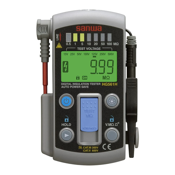
[3] PARTS IDENTIFICATION 3-2 Measurement Probe, Alligator Clip Barrier 3-1 Body LED light LED level meter (MΩ) Detachable variable angle measurement probe Alligator clip (CL-561) Connector Display Barrier Power button Light button Measurement probe (TL-561) MΩ Test button Detachable alligator clip 3-3 Display ①... -
Page 6: Description Of Functions
[4] DESCRIPTION OF FUNCTIONS 4-4 Button Automatic Locking Feature Approx. 15 sec. after the last button operation, the button 4-1 Changing the Angle of the Measurement Probe automatic locking feature will be activated with the beep To change the angle of the measurement probe, pull the probe sound. -
Page 7: Mω Test Button (Mω Function)
[5] MEASURING PROCEDURE 4-7 MΩ test button (MΩ function) Press the top of the button to generate a test voltage WARNING just while the button is pressed. To make continuous measurement, set the button up. 1. Do not apply any input signal exceeding the max. To stop the measurement, release the button or lay it down rated value for each function. -
Page 8: Voltage Measurement
3) Measuring procedure ① Set the V function. ② Connect the alligator clip to the circuit to be measured ② and the measurement probe too. ③ Read the display. ② ② ③ ① 5-2 Voltage Measurement AC voltage (ACV), DC voltage (DCV) Automatic detection ③ ③ WARNING ① ① Do not apply any input signal exceeding the max. -
Page 9: Insulation Resistance Measurement
5-3 Insulation Resistance Measurement Test voltage selection mode WARNING The instrument makes only necessary voltages enabled between 15 V, 25 V, 50 V, 100 V, 125 V, 250 V, and 500 V. 1. Do not apply any voltage to the measuring terminals. Only the selected test voltages can be used after the 2. - Page 10 Note: Example of insulation resistance measurement If the power is turned off during the test voltage selection mode, the selected voltages before the time will not be reflected. The selection completes after is indicated on the display. The selected test voltages are memorized into the instrument, and only the selected voltages can be used when the power is turned on again after being turned off.
-
Page 11: Discharge Function
How to read the LED level meter when the test voltage is After the measurement, the instrument holds the last 15 V, 25 V, or 50 V. reading on the display, and starts the automatic discharge. When a voltage of the circuit to be measured decreases to Reading LED level meter 30 V or lower,... -
Page 12: Maintenance
2) Measuring ranges [6] MAINTENANCE Function Measuring WARNING Accuracy Remarks range 1. The followings are important to safety. Read this Resistance ≦ 30 Ω: Beeps 999.9 Ω manual throughly to maintain the instrument. measurement 9.999 kΩ: 99.99 kΩ ±(1.5 %rdg + 7 dgt) 2. Calibrate and inspect the instrument at least once a Not supported Continuity 999.9 kΩ... -
Page 13: Storage
Sanwa offers comprehensive warranty services to its end- ② Remove the battery door and replace all the 4 batteries users and to its product resellers. Under Sanwa's general warranty policy, each instrument is warranted to be free with new ones according to the battery mark inside the from defects in workmanship or material under normal battery holder. -
Page 14: Sanwa Web Site
Low battery become higher than the price of the product. Please indication the function): indicated contact Sanwa authorized agent / service provider in Altitude: ≦ 2,000 m, Pollution degree: II, Operating conditions advance. Indoor use only 0 ℃ to 40 ℃ : 90 %RH (Max.) non-... -
Page 15: Measuring Range And Accuracy
8-2 Measuring Range and Accuracy Resistance, Continuity Accuracy: ±(% rdg + dgt) Range Accuracy rdg: reading dgt: least significant digit 999.9 Ω Temperature: 23±5 ℃ 99.99 kΩ ±(1.5 %rdg + 7 dgt) Humidity: < 75 % R.H. without condensation 999.9 kΩ External magnetic field: negligible small Battery voltage: within the battery effective rage • Open circuit voltage: Approx. - Page 16 本社 = 東京都千代田区外神田2−4−4・電波ビル 郵便番号 = 101-0021・電話 = 東京 (03) 3253−4871㈹ 大阪営業所 = 大阪市浪速区恵美須西2−7−2 郵便番号 = 556-0003・電話 = 大阪 (06) 6631−7361㈹ SANWA ELECTRIC INSTRUMENT CO.,LTD. Dempa Bldg., 4-4 Sotokanda2-Chome Chiyoda-Ku,Tokyo,Japan This manual employs soy ink. 04-1704 5008 6009...
Need help?
Do you have a question about the HG561H and is the answer not in the manual?
Questions and answers