
Related Manuals for Omega DRST-CM


Summary of Contents for Omega DRST-CM
- Page 1 User’s Guide Shop online at omega.com e-mail: info@omega.com For latest product manuals: www.omegamanual.info DRST-CM Communication Enabler...
- Page 2 Fax: (203) 359-7700 e-mail: info@omega.com For Other Locations Visit omega.com/worldwide The information contained in this document is believed to be correct, but OMEGA accepts no liability for any errors it contains, and reserves the right to alter specifications without notice.
-
Page 3: Table Of Contents
Table of Contents DRST-CM Transmitter Table of Contents Section ................ Page Section 1 Warning ..................5 Section 2 Symbol Identification ..............5 Section 3 Safety Instructions ................ 6 Section 4 Applications ................... 7 Section 5 Technical Characteristics ............. 7 Section 6 Mounting/ Installation/ Programming ........8 Section 7 Mounting on a DRST device ............ -
Page 4: Section 1 Warning
HAZARD OUS Troubleshooting the device. VOLTAGE WARNING Repair of the device must be done by Omega A/S only. CAUTION Section 1.2 - Symbol Identification Triangle with an exclamation mark: Read the manual before installation and commissioning of the device in order to avoid incidents that could lead to personal injury or mechanical damage. -
Page 5: Section 3 Safety Instructions
Liability To the extent the instructions in this manual are not strictly observed, the customer cannot advance a demand against Omega A/S that would otherwise exist according to the concluded sales agreement. -
Page 6: Section 4 Applications
• Programmed parameters can be protected by a user-defined password. • When mounted on devices that are installed upside down, a menu item allows the display on the DRST-CM to be rotated 180o and the up/down buttons to switch function. -
Page 7: Section 6 Mounting/ Installation/ Programming
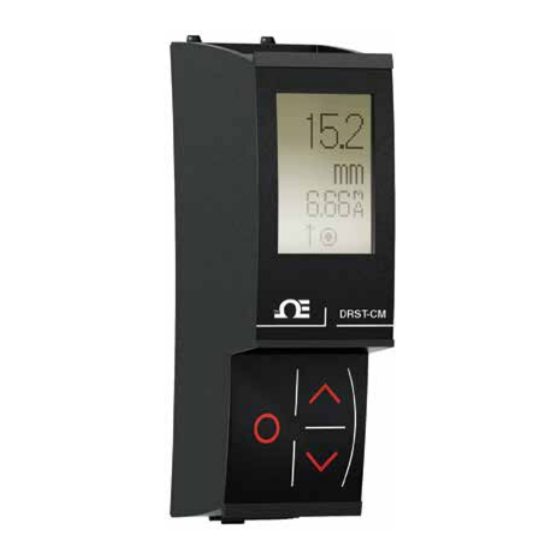
Mounting on a DRST device Section 7.1 - Mounting on a DRST device DRST-CM is a detachable display that can be mounted on all DRST fronts for programming and signal monitoring. DRST-CM contains a four line LCD dot display Line 1 can e.g. show the scaled process value. -
Page 8: Section 9 Electrical Specifications
Electrical Specification Section 9 - Electrical specifications Environmental conditions: Specifications range ....... -20°C to +60°C Storage temperature . - Page 9 Electrical Specification Section 9 - Electrical Specification Modbus RTU DRST-CM DRST-CM DRST-CM PLC/DCS HMI/PC DRST DRST DRST Gateway Zone 2 / Cl. 1, Div. 2, gr. A-D Safe Area Modbus RTU Modbus RTU DRST-CM DRST-CM DRST-CM PLC/DCS DRST DRST DRST...
- Page 10 RS485 networks, at speeds up to 115,200 bps. The most common speeds are 9,600 bps and 19,200 bps. Modbus RTU is the most widely used industrial protocol and is supported by the DRST-CM. Modbus RTU: To communicate with a slave device, the master sends a message containing: Device Address - Function Code - Data - Error Check The Device Address is a number from 0 to 247.
-
Page 11: Section 10 Modbus Parameter Settings
Modbus slave addressing range: 1 - 247 (247 = default address) Modbus Parameter Storage: Saved in non-volatile memory in the DRST-CM device (Factory Default Values are marked in bold) Modbus RTU segment line termination: A 120 Ohm resistor should be installed on both ends of a RS485 Modbus RTU segment loop to prevent... -
Page 12: Section 11 Modbus Settings - Routing Diagram
The Modbus submenu is located somewhere in the menu structure of any host [12] NONE device supporting DRST-CM. The actual place is definedfor each particular The gray shaded menus/texts are only shown for guidance, and are not part of device. -
Page 13: Section 11 Modbus Settings - Routing Diagram
Modbus settings- Routing Diagram DRST-CM Modbus settings - Routing Diagram cont. Default settings: Baud rate: 19.2 kbps Parity mode: Even Stop bit: Address: Reponse delay: 0 ms... - Page 14 Department will issue an Authorized Return (AR) number immediately upon phone or written request. Upon examination by OMEGA, if the unit is found to be defective, it will be repaired or replaced at no charge. OMEGA’s WARRANTY does not apply to defects resulting from any action of the purchaser, including but not limited to mishandling, improper interfacing, operation outside of design limits, improper repair, or unauthorized modification.
- Page 15 Where Do I Find Everything I Need for Process Measurement and Control? OMEGA…Of Course! Shop online at omega.com TEMPERATURE M U Thermocouple, RTD & Thermistor Probes, Connectors, Panels & Assemblies M U Wire: Thermocouple, RTD & Thermistor M U Calibrators & Ice Point References M U Recorders, Controllers &...
Need help?
Do you have a question about the DRST-CM and is the answer not in the manual?
Questions and answers