Table of Contents
Advertisement
Quick Links
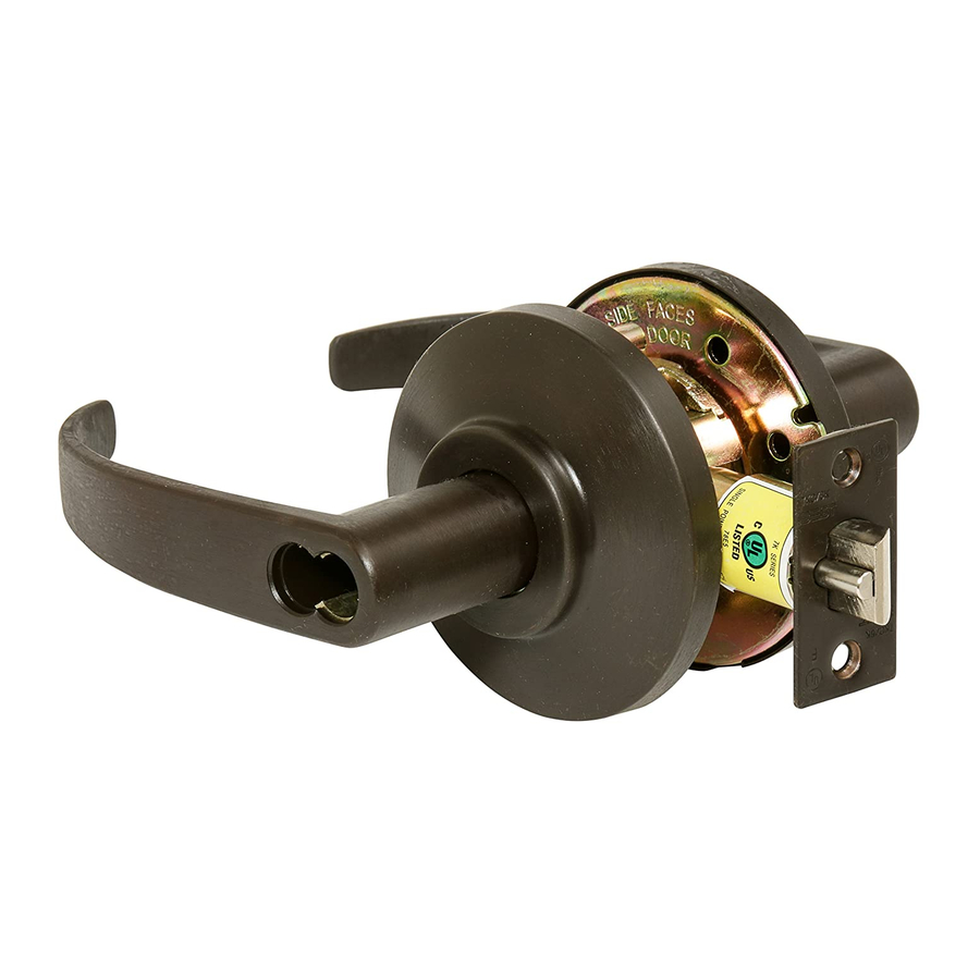
For factory prepared doors only
Inside rose
Through-bolts
Inside liner
Outside rose
Figure 1
Caution: If you use hollow metal doors, determine whether the
doors are reinforced enough to support the lock. If door rein-
forcement is not adequate, consult the door manufacturer for
information on proper reinforcement.
Simplified instructions
1 Install the latch so that the bevel on the latchbolt faces the strike.
2 Disassemble the inside trim.
3 Install the outside lever unit. Make sure to screw the stud bolts into
the liner assembly.
4 Install the liner, rose, lever, and strike.
For field door preparation and detailed installation instructions, see the
following steps.
1
Position template
T E M P
L A T E
Figure 2—Positioning the template
1 Fold the template and place in position on the high edge of the door
bevel as shown in Figur e2.
2 Mark the drill points.
Note: Suggested height from floor to centerline of the lock is 40 5/16. "
If steel frames are used, the latch centerline must be in line with the cen-
ter of the strike preparation.
T56062/Rev – 1797905 ER-799 1 -19 Mar 2000
Installation Instructions
for 7K Cylindrical Locks
Latch
High edge of door bevel
BEST ACCESS SYSTEMS
2
Bore and drill holes
Figure 3—Installing the boring jig
Note: For 2 3/8" backset locks, locate and drill the holes according to
the paper template. For 2 3/4" locksets use the following steps.
1 Bore a 2 1/8" diameter hole from both sides of the door, to the center
of the door as shown in Figure 4.
2 Drill a 1" diameter hole from the edge of the door that intersects the
2 1/8" hole.
3 Cut out notches for liner tabs on both sides of the door.
4 Install the boring jig (KD303) into the door. Make sure the front edge
of the jig is parallel with the door edge (see Figure 3).
5 Drill two 5/16" diameter holes halfway only into the keyed side of
the door.
Note: Replace the boring jig after ten door preparations.
3
Install latch
2 1/8" dia. hole
Notches for liner tabs
1" dia. hole
Latch
Figure 4—Boring two holes and installing the latch
1 Mortise the door edge for the latch face.
2 Install the latch and check the door swing. Latch hubs should project
into the 2 1/8" diameter hole.
Note: For "L" function privacy locks, be sure to use the "L" function
latch. See Figure 4.
Indianapolis, Indiana
Door edge
5/16" diameter
Boring jig
Non-L function
L function
Advertisement
Table of Contents

Related Manuals for BEST ACCESS SYSTEMS 7K


Summary of Contents for BEST ACCESS SYSTEMS 7K
- Page 1 Installation Instructions for 7K Cylindrical Locks For factory prepared doors only Bore and drill holes Inside rose Door edge Through-bolts 5/16" diameter Inside liner Outside rose Latch Boring jig Figure 3—Installing the boring jig Note: For 2 3/8" backset locks, locate and drill the holes according to the paper template.
- Page 2 Note 2: The outside lever must be in the For all levers (including turnbutton levers): Note: To remove the core reverse these steps. UNLOCKED position during installation. 1 Push the lever on completely. T56062/Rev – 1797905 ER-799 1 -19 Mar 2000 BEST ACCESS SYSTEMS Indianapolis, Indiana...
Need help?
Do you have a question about the 7K and is the answer not in the manual?
Questions and answers