
Related Manuals for Technibel MCA451R


Summary of Contents for Technibel MCA451R
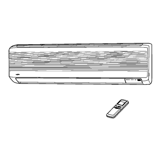
- Page 1 TECHNICAL DATA & SERVICE MANUAL Indoor Unit Outdoor Unit MCA451R GR451R MCA601R GR601R SPLIT SYSTEM AIR CONDITIONER INDOOR UNIT OUTDOOR UNIT 0.8180.247.1 06/2002...
- Page 2 Important! When Transporting Be careful when picking up and moving the indoor and Please Read Before Starting outdoor units. Get a partner to help, and bend your knees when lifting to reduce strain on your back. Sharp This air conditioning system meets strict safety and edges or thin aluminum fins on the air conditioner can operating standards.
-
Page 3: Table Of Contents
Table of Contents Page OPERATING RANGE SPECIFICATIONS 2-1. Unit Specifications 2-2. Major Component Specifications 2-3. Other Component Specifications DIMENSIONAL DATA REFRIGERANT FLOW DIAGRAM PERFORMANCE DATA 5-1. Performance Charts 5-2. Air Throw Distance Chart 5-3. Cooling Capacity 5-4. Heating Capacity ELECTRICAL DATA 6-1. -
Page 4: Operating Range
1. OPERATING RANGE Temperature Indoor Air Intake Temp. Outdoor Air Intake Temp. Maximum 32°C D.B. / 23°C W.B. 46°C D.B. Cooling Minimum 19°C D.B. / 14°C W.B. 19°C D.B. Maximum 27°C D.B. 24°C D.B. / 18°C W.B. Heating Minimum – 8°C D.B. / – 9°C W.B. -
Page 5: Specifications
2. SPECIFICATIONS 2-1. Unit Specifications Indoor Unit MCA451R Outdoor Unit GR451R Power Source 230 V Single phase 50 Hz Voltage rating Cooling Heating 4400 5000 Capacity BTU/h 15020 17065 Air circulation (High) Moisture removal (High) Liters/h — Available voltage range... - Page 6 Indoor Unit MCA601R Outdoor Unit GR601R Power Source 230 V Single phase 50Hz Voltage rating Cooling Heating 5500 6200 Capacity BTU/h 18770 21160 Air circulation (High) Moisture removal (High) Liters/h — Available voltage range 198 to 264 Running amperes 10.2 Power input 2200 2100...
-
Page 7: Major Component Specifications
2-2. Major Component Specifications 2-2-1. Indoor Unit Indoor Unit MCA451R MCA601R Part No. Controls Microprocessor Control circuit fuse 250 V – 3.15 A Remote Control Unit RC– 2 ( R C ) Type Cross-flow Q´ty ... Dia. and length 1 ... ø88 / L746 Fan motor model ... - Page 8 Outdoor Unit GR451R Type Rotary (Hermetic) Compressor model PH 28 VSRT Nominal output 1250 Compressor oil ... Amount DIAMOND MS 32(N1)...670 Ω Coil resistance (Ambient temp. 20°C) C – R : 1.43 C – S : 2.40 Type Internal protector Safety devices Operating temp.
- Page 9 Outdoor Unit GR601R Type Rotary (Hermetic) Compressor model PH 36 VTRT Nominal output 1600 Compressor oil ... Amount DIAMOND MS 32(N1)...900 Ω Coil resistance (Ambient temp. 20°C) C – R : 1.06 C – S : 2.03 Type Internal protector Safety devices Operating temp.
-
Page 10: Other Component Specifications
2-3. Other Component Specifications Indoor Unit MCA451R MCA601R Thermistor (Coil sensor) NTC - SENSOR Resistance (at 25°C) kΩ 10 ± 5 % Thermistor (Room sensor) NTC - SENSOR Resistance (at 25°C) kΩ 10 ± 5 % Outdoor Unit GR451R GR601R... -
Page 11: Dimensional Data
3. DIMENSIONAL DATA Indoor Unit MCA451R MCA601R Remote control unit 18.5 147.5 147.5 Center of tubing hole (2 places) Drain hose ø18 Narrow tube ø6.35 (1/4") Wide tube ø12.7 (1/2") MCA451,601R Unit : mm... - Page 12 Outdoor Unit GR451R GR601R Air intake 4 – ø12 holes Air discharge Wide tube service valve ø12.7 (1/2") Narrow tube service valve ø6.35 (1/4") Unit : mm...
-
Page 13: Refrigerant Flow Diagram
4. REFRIGERANT FLOW DIAGRAM... - Page 14 Insulation of Refrigerant Tubing IMPORTANT Because capillary tubing is used in the outdoor unit, both the wide and narrow tubes of this air conditioner become cold. To prevent heat loss and wet floors due to dripping of condensation, both tubes must be well insulated with a proper insulation material.
-
Page 15: Performance Data
5. PERFORMANCE DATA 5-1. Performance charts Indoor Unit MCA451R MCA601R Outdoor Unit GR451R GR601R Cooling Characteristics Heating Characteristics Indoor inlet air Indoor inlet air D.B. temp. (°C) D.B. temp. (°C) Outdoor fan speed High –5 Outdoor inlet air D.B. temp. (°C) Outdoor inlet air D.B. -
Page 16: Air Throw Distance Chart
5-2. Air Throw Distance Chart Indoor Unit MCA451R MCA601R Cooling Room air temp. : 27°C Fan speed High Horizontal distance (m) : Flap angle 0° , : Axis air velocity 0° : Flap angle 30°, : Axis air velocity 30°... -
Page 17: Cooling Capacity
5-3. Cooling Capacity INDOOR UNIT: MCA451R GR451R OUTDOOR UNIT: RATING CAPACITY 4,4 kW AIR FLOW RATE 760 m³/h EVAPORATOR CONDENSER ENT.TEMP. °C OUTDOOR AMBIENT TEMP. °C W.B. D.B. 4,17 4,05 3,85 3,62 3,34 1,29 1,38 1,48 1,63 1,77 2,86 2,80... - Page 18 INDOOR UNIT: MCA601R GR601R OUTDOOR UNIT: RATING CAPACITY 5,5 kW AIR FLOW RATE 760 m³/h EVAPORATOR CONDENSER ENT.TEMP. °C OUTDOOR AMBIENT TEMP. °C W.B. D.B. 5,21 5,06 4,82 4,52 4,17 1,81 1,93 2,08 2,28 2,48 3,57 3,50 3,38 3,24 3,07 4,05 3,97 3,85...
-
Page 19: Heating Capacity
5-4. Heating Capacity Indoor Unit MCA451R MCA601R Outdoor Unit GR451R GR601R –8 –5 Outdoor temperature (°C D.B.) NOTE … Point of Rating condition Black dot in the chart indicate the following rating condition. Indoor : 20°C D.B. Outdoor : 7°C D.B. / 6°C W.B. -
Page 20: Electrical Data
6. ELECTRICAL DATA 6-1. Electrical Characteristics Indoor Unit MCA451R Outdoor Unit GR451R COOLING Indoor Unit Outdoor Unit Complete Unit Fan Motor Fan Motor Compressor Performance at 230 V Single phase 50 Hz Rating Conditions Running Amps. 0.37 0.50 6.33 Power Input 0.070... - Page 21 Indoor Unit MCA601R Outdoor Unit GR601R COOLING Indoor Unit Outdoor Unit Complete Unit Fan Motor Fan Motor Compressor Performance at 230 V Single phase 50 Hz Rating Conditions Running Amps. 0.37 0.55 9.08 10.0 Power Input 0.070 0.120 2.01 Full Load Conditions Running Amps. 0.37 0.55 10.08...
-
Page 22: Electrical Wiring Diagrams
6-2 Electric Wiring Diagrams To avoid electrical shock hazard, be sure to disconnect power before checking, servicing WARNING and/or cleaning any electrical parts. Indoor Unit MCA451R MCA601R Outdoot Unit GR451R GR601R... -
Page 23: Function
7.FUNCTION 7-1 Cool Mode Operation (RT - SPT) [ over 3 min over 5 min COMP OFAN over 30 sec IFAN In Cool Mode, the operation of the Compressor (COMP), Outdoor Fan (OFAN) and Indoor Fan (IFAN) are determined by the difference between the Room Temperature (RT) and the Set Point Temperature (SPT) as in the graph above. -
Page 24: Heat Mode Operation
7-2 Heat Mode Operation (RT - SPT) [ COMP 30 sec IFAN Note 1 Note 2 The Heat Mode operation is similar to the Cool Mode operation. The COMP, OFAN and IFAN are mainly controlled by the value of (RT – SPT). In the graph above, the IFAN is operating in Auto Fan speed mode. Therefore, the IFAN speed changes automatically according to the (RT - SPT). -
Page 25: Auto Mode Operation
7-3 Auto (Cool/Heat) Mode Operation (RT - SPT) [ COMP & OFAN Auto Heat Mode Auto Cool Mode Auto Heat Mode In Auto Mode, the unit switches between the Auto Cooling Mode and Auto Heating Mode automatically to maintain the room temperature (RT) at the set point temperature (SPT). -
Page 26: Dry Mode Operation
7-4 Dry Mode Operation (RT - SPT) [ Time [min] DRY-ON DRY-OFF IFAN 5 minutes COMP ON time COMP & OFAN 3.5 min Max 15 minutes Max 15 minutes 6 min (Note 2) (Note 1) In Dry Mode, the unit operates in a mild cool mode to lower the humidity of the room. In order to maintain a high efficiency in the drying operation without over lowering the room temperature excessively, the Dry Mode is different from the Cool Mode in two ways. -
Page 27: Protection Operations In Cool And Dry Modes
7-6 Protection Operations in Cool and Dry Modes 1. Indoor Coil Defrost Protection The in-coil defrost protection can prevent the ice formation at the in-coil when the ambient temperature is low. ICT [ OFAN COMP IFAN t1 = 5 min minimum for each COMP starting t2 = OFAN cycling (alternate between ON and OFF every 30 sec) for 20 min maximum t3 = COMP and OFAN stop for 10 min minimum... - Page 28 2. Outdoor Coil High Pressure Protection The out-coil high pressure protection prevent the build up of high pressure at the out-coil during cooling operation. OCT [ COMP COMP is forced OFF OFAN follow operation of COMP OFAN OFAN is forced ON (Note 1) IFAN IFAN is forced LOW OPER...
-
Page 29: Protection Operations In Heat Mode
7-7 Protection Operations in Heat Mode 7-7-1 Outdoor Coil Deice Protection The deice process is controlled by an Ice Detection Algorithm (IDA). The IDA is an unique control algorithm incorporated to maintain optimal utilization of the heat pump capacity, especially in below-zero outdoor temperature condition. - Page 30 1st COMP start, OR deice complete Reset TLD cnt to 0 DTF = 0 IFAN/OFAN speed change Reset SCT cnt to 0 DTF = 0 TLD > TST SCT > SCD DDT = OCT - TempD DTF = 1 DDT and DTF information to main algorithm Explanation: The “Ice Forming Detection”...
- Page 31 7-7-2Indoor Coil High Pressure Protection in Heat Mode The in-coil high pressure protection prevent the build up of high pressure at the in-coil during heating operation. ICT [ COMP is forced OFF COMP OFAN Note: The operation temperatures shown as A and B in the chart differ by models. MODEL 1 MODEL 2 MODEL 3...
-
Page 32: Cold Draft Prevention (Heating)
7-8 Cold Draft Prevention (Heating) • This function controls indoor fan speed so a strong draft of cold air will not blow out before the indoor heat exchange coil have sufficiently warmed up. • When 10 minutes has elapsed, the fan speed is automatically switched to set speed regardless of indoor heat exchange coil temperature. -
Page 33: Sleep Function
7-9 Sleep Function Room temperature is automatically controlled to compensate for body temperature variations while sleeping. This mode of operation is designed for maximal comfort in both COOL and HEAT modes. Unit is turned to SB 7-12 Hours Sleep operation after Sleep SPT+3 Cool, Dry modes... -
Page 34: Manual Unit Control And Led Indicators
7-13 Manual Unit Control and LED indicators The push button switch and the LED indicators on the display panel let the user to control the unit operation without a remote controller. Their operations are provided below. LED indicators: 1. Lights up when the Air Conditioner is connected to power and STAND BY ready to receive the R/C commands INDICATOR... -
Page 35: Troubleshooting
8. TROUBLESHOOTING 8-1. Check before and after troubleshooting WARNING Hazardous voltage can cause ELECTRIC SHOCK or DEATH. Disconnect power or turn off circuit breaker before you start checking or servicing. 8-1-1. Check power supply wiring. Check that power supply wires are correctly connected to terminals L and N on the terminal plate in the outdoor unit. -
Page 36: Air Conditioner Does Not Operate
8-2. Air conditioner does not operate. 8-2-1. Circuit breaker trips (or fuse blows). A. When the circuit breaker is set to ON, it is tripped soon. (Resetting is not possible.) There is a possibility of ground fault. Check insulation resistance. If resistance value is 2MΩ... - Page 37 B. Circuit breaker trips in several minutes after turning the air conditioner on. There is a possibility of short circuit. • Check capacity of circuit breaker. Replace with suitable one (larger capacity). Capacity of circuit breaker is suitable. In case of Heating operation : Measure resistance of outdoor fan •...
- Page 38 C. Check remote control unit. • Try to run with another remote control unit. First remote control unit is defective. • Check for residue buildup on Clean transmitter. transmitter of remote control unit. • Check for residue buildup on remote Clean receiver.
- Page 39 8-2-3. Only outdoor unit does not run. A. Check setting temperature. COOL HEAT Is room temperature too low ? Is room temperature too high ? Try to lower setting temperature by Try to raise setting temperature by temperature setting button ( button).
-
Page 40: Some Part Of Air Conditioner Does Not Operate
8-3. Some part of air conditioner does not operate. 8-3-1. Only indoor fan does not run. • Check fan casing Remove foreign foreign matter on matter or repair. Fan cannot inside. be turned. • Check fan rotation. Turn fan gently once or twice by hand. - Page 41 8-3-3. Only outdoor fan does not run. • Check fan casing Remove foreign foreign matter on matter or repair. Fan cannot inside. be turned. • Check fan rotation. Turn fan gently once or twice by hand. Fan motor burnout or foreign matter in Repair or replace.
-
Page 42: Air Conditioner Operates, But Abnormalities Are Observed
8-4. Air conditioner operates, but abnormalities are observed. 8-4-1. Operation does not switch from HEAT to COOL (or COOL to HEAT). • Remote control unit may be defective. Receiver in lamp Ass'y may be defective. • Measure resistance of 4–way valve's winding. - Page 43 8-4-2. Poor cooling or heating. • Check position of remote control unit. Change position of remote Cool or warm air from air conditioner • control unit. reaches position directly. • Wide and narrow tubes between Insulate both wide and narrow indoor unit and outdoor unit are tubes separately and then insulated.
-
Page 44: If A Sensor Is Defective
8-5. If a sensor is defective. 8-5-1. Indoor coil temp. thermistor is defective. • Operation lamp on front side of • Thermistor (TH1 ) is defective. indoor unit is flashing on and off. (*) • Replace thermistor. Alarm Signal (*) NOTE Operation lamp on the front side of the indoor unit will flash on and off when the indoor coil thermistor is defective. -
Page 45: Checking Electrical Components
9. CHECKING ELECTRICAL COMPONENTS 9-1. Measurement of Insulation Ground wire Resistance Clip The insulation is in good condition if the resistance exceeds 2MΩ. Probe 9-1-1. Power Supply Wires Insulation tester Fig. 1 Clamp the ground wire of the power supply wires with the lead clip of the insulation resistance tester and Terminal plate measure the resistance by placing a probe on either of... -
Page 46: Checking Continuity Of Fuse On Pcs Ass'y
9-2. Checking Continuity of Fuse on PCB Ass'y Fuse Remove the PCB Ass’y from the electrical component box. Then pull out the fuse from the PCB Ass’y. (Fig. 5) PCB Ass’y Check for continuity using a multimeter as shown in Fig.
Need help?
Do you have a question about the MCA451R and is the answer not in the manual?
Questions and answers