
Subscribe to Our Youtube Channel
Related Manuals for HIKVISION DS-PK00 series


Summary of Contents for HIKVISION DS-PK00 series
- Page 1 Network Security Control Panel User Manual Network Security Control Panel User Manual UD07466B...
- Page 2 SURVEILLANCE LAWS VARY BY JURISDICTION. PLEASE CHECK ALL RELEVANT LAWS IN YOUR JURISDICTION BEFORE USING THIS PRODUCT IN ORDER TO ENSURE THAT YOUR USE CONFORMS THE APPLICABLE LAW. HIKVISION SHALL NOT BE LIABLE IN THE EVENT THAT THIS PRODUCT IS USED WITH ILLEGITIMATE PURPOSES.
- Page 3 Network Security Control Panel User Manual IN THE EVENT OF ANY CONFLICTS BETWEEN THIS MANUAL AND THE APPLICABLE LAW, THE LATER PREVAILS. 0201001061111 Regulatory Information FCC Information Please take attention that changes or modification not expressly approved by the party responsible for compliance could void the user’s authority to operate the equipment.
- Page 4 Network Security Control Panel User Manual European standards listed under the R&TTE Directive 1999/5/EC, the EMC Directive 2004/108/EC, the LVD Directive 2006/95/EC, the RoHS Directive 2011/65/EU. 2012/19/EU (WEEE directive): Products marked with this symbol cannot be disposed of as unsorted municipal waste in the European Union. For proper recycling, return this product to your local supplier upon the purchase of equivalent new equipment, or dispose of it at designated collection points.
- Page 5 Network Security Control Panel User Manual that the equivalent isotropically radiated power (e.i.r.p.) is not more than that necessary for successful communication. Conformément à la réglementation d'Industrie Canada, le présent émetteur radio peut fonctionner avec une antenne d'un type et d'un gain maximal (ou inférieur) approuvé pour l'émetteur par Industrie Canada.
- Page 6 Network Security Control Panel User Manual or moisture. This installation should be made by a qualified service person and should conform to all the local codes. Please install blackouts equipment into the power supply circuit for convenient supply interruption.
-
Page 7: Table Of Contents
Content Chapter 1 System Introduction ____________________________________ 3 1.1 Overview ______________________________________________________ 3 1.2 System Definition _______________________________________________ 3 1.2.1 Partition _________________________________________________________ 3 1.2.2 Public Partition ____________________________________________________ 3 1.2.3 Zone ____________________________________________________________ 4 1.2.4 Zone Type ________________________________________________________ 4 1.2.5 Relay ____________________________________________________________ 6 1.2.6 User Operations ___________________________________________________ 6 Chapter 2 System Controlling _____________________________________ 8 2.1 Keypad Introduction _____________________________________________ 8... - Page 8 Network Security Control Panel User Manual 2.3.24 Control Panel Soft Recovery _________________________________________ 45 2.3.25 Auto-Search _____________________________________________________ 45 2.3.26 Auto-Registration _________________________________________________ 46 2.3.27 Signal Strength Query _____________________________________________ 47 2.3.28 Keypad Locking and Unlocking ______________________________________ 47 Chapter 3 Trouble Shooting _____________________________________ 48...
-
Page 9: Chapter 1 System Introduction
Network Security Control Panel User Manual Chapter 1 System Introduction 1.1 Overview Network security control panel uses embedded microcontroller technology for zone monitoring and system status detection. The alarm or status reports can be transmitted to the central alarm monitoring station through programming. Multiple alarm types and report transmission methods (telephone network, the Ethernet network, and the GPRS wireless network) are supported. -
Page 10: Zone
Network Security Control Panel User Manual public partition are in the arming status. The public partition is disarmed automatically when any of partitions linked with the public partition is in the disarming status. The user also can arm or disarm the public partition independently. ... - Page 11 Network Security Control Panel User Manual not be affected by arming and disarming operation or be bypassed. When the zone detects alarm events, the sound and light alarming prompt will be triggered on the keyboard. The siren output will be triggered when the siren is linked, meanwhile the generated event report will be uploaded to the center receiver (the uploaded report is different with the report of 24-Hr Audible Alarm Zone), and the zone...
-
Page 12: Relay
Network Security Control Panel User Manual Interior Follower Zone After arming the system, if the delayed Zone is first triggered, the system will provide an entry delay when the interior follower zone is triggered. If not, the interior follower zone will trigger alarm instantly. The delay parameters of interior follower zone are the same with the e delayed zone. - Page 13 Network Security Control Panel User Manual the detection area are bypassed (such as PIR detectors). People can move inside the area and not trigger alarm. Disarming If you want to turn off the arming of the detectors, you should disarm the system. Then the zones that disarmed are not protected, even an event occurs and triggers the detectors, and no alarm will be trigger by controller.
-
Page 14: Chapter 2 System Controlling
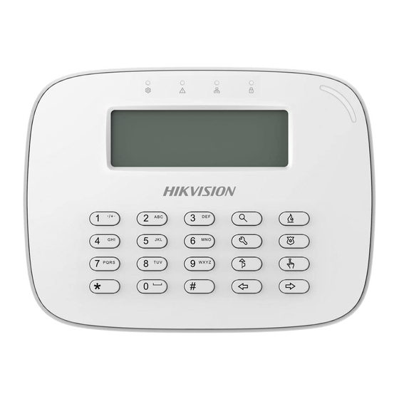
Network Security Control Panel User Manual Chapter 2 System Controlling 2.1 Keypad Introduction Take DS-PK00 series keypad as an example. Please refer to the user manual based on the corresponded model for other appearance. Description Keypad LED/LCD Screen Control Panel... -
Page 15: Keypad Indicator
Network Security Control Panel User Manual Button Description Operating Indicator Power Indicator Arming Indicator Stay Arming Indicator 2.2 Keypad Indicator For configuring the security control panel, you should restore the system of the control panel after start-up. 2.2.1 Control Panel Start-up The keypad registration will be completed in 32 seconds after the control panel being power on. - Page 16 Network Security Control Panel User Manual Working Status Indicator Working Status Indicator Partition System Partition Armed Solid Red Solid Green Disarmed Password Modifying Flicking Green Fob Code Matching Flicking Green Testing Mode Solid Red Programming Flicking Green OPERATING Working Status Indicator Working Status Indicator...
- Page 17 Partition5 Ready SYS6R Partition6 Ready SYS7R Partition7 Ready SYS8R Partition8 Ready Partition Keypad Keypad Standby Status Display Demonstration The standby status display demonstration is shown below. HIKVISION SYS1D SYS2R SYS3A SYS4R SYS5R SYS6R SYS7R SYS8R V1.2.1 build 131211 2014.04.18 19:24:26...
- Page 18 Network Security Control Panel User Manual The LCD keypad displays the version of the control panel and the time of operation. Global Keypad Programming Status Display Demonstration The programing status includes normal status and abnormal status. The demonstration is shown below. Normal Status Abnormal Status System Status (abnormal) Display Demonstration...
-
Page 19: Buzzer Description
Network Security Control Panel User Manual Work Test 001 002 003 004 005 006 System Fault Display Demonstration The system fault display demonstration is shown below. Display Demonstration in Project Mode The demonstration is shown below. 2.2.3 Buzzer Description Sound Prompt Description Pressing keys prompt;... -
Page 20: Keypad Operation Code
Network Security Control Panel User Manual Sound Prompt Description Three Long Beeps and The tampering prevention of the keyboard is turned Two Short Beeps Three Beeps Registering the keyboard completed. One Beep In Two Two minutes before auto arming/disarming; One Seconds minute before arming for temporary password. -
Page 21: Device Initialization
Network Security Control Panel User Manual 2.3.1 Device Initialization Function: The control panel can be recovered through the alarm keypad initialization. Command:[Installer Password] + [*] + [8] + [9] + [#] Demonstration: LCD Display E.g., installer password is 012345. Press installer password: [0] [1] [2] [3] [4] [5]. -
Page 22: Zone Bypass Operation
Network Security Control Panel User Manual Demonstration: LCD Display E.g., the user password is 1234. Arming: The current status is status of disarming. Press user password: [1] [2] [3] [4]. Press [#], If the operation is successful, status of disarming will changed into arming. - Page 23 Network Security Control Panel User Manual Demonstration: E.g., the user password is LCD Display 1234, and the zone No. Is Press the user password: [1] [2] [3] [4]. Press the bypass key: Press the zone No.: [0] [3]. Press [#] to confirm the If the operation is successful, operation.
- Page 24 Network Security Control Panel User Manual Demonstration: E.g., the user password is LCD Display 1234, and the zone is No. 03, No. 04, and No. 05. Press the user password: [1] [2] [3] [4]. Note: For the continuous bypass operation, the user password is required to be entered once only.
-
Page 25: Instant Arming
Network Security Control Panel User Manual Multi-zones bypass/bypass recovery should be conducted in 15 seconds. For example, bypass operations of the zone No. 04 and zone No. 05 should be completed in 15 seconds in the above demonstration. 2.3.4 Instant Arming Function: The control panel can be set into the instant arming status via the keypad. -
Page 26: Force Arming
Network Security Control Panel User Manual Demonstration: LCD Display E.g., the user password is 1234. Press the user password: [1] [2] [3] [4]. Press [*] to enter the working mode. Press [4], and the control panel enters stay arming status. Press [#] to confirm the If the operation is successful, operation. - Page 27 Network Security Control Panel User Manual Demonstration: LCD Display E.g., the user password is 1234, and the zone number is 03. Press the user password: [1] [2] [3] [4]. Press the bypass key: Press [#] to confirm the If the operation is successful, operation.
- Page 28 Network Security Control Panel User Manual Demonstration: LCD Display E.g.,the user password is 1234. Press user password: [1] [2] [3] [4]. Press [*] to enter the working mode. Press[7], control panel enters force instant arming status. Press the bypass key: Press [#] to confirm the If the operation is successful, operation.
-
Page 29: Canceling Keypad Alarm
Network Security Control Panel User Manual Demonstration: LCD Display E.g.,the user password is 1234. Press user password: [1] [2] [3] [4]. Press [*] to enter the working mode. Press [4], control panel enters the force stay arming status. Press the bypass key: Press [#] to confirm the If the operation is successful, operation. - Page 30 Network Security Control Panel User Manual Demonstration: LCD Display E.g., the user password is 1234. Press the user password: [1] [2] [3] [4]. Press [*] to enter the working mode. Press [1] to cancel the alarm under the arming status. Press [#] to confirm the operation operation.
- Page 31 Network Security Control Panel User Manual Demonstration: LCD Display E.g., the user password is 1234. Press the user password: [1] [2] [3] [4]. Press [*] to enter the working mode. Press [1] to cancel the alarm under the disarming status. Press [#] to confirm the If the operation is successful, operation.
-
Page 32: Single-Zone Operation
Network Security Control Panel User Manual Demonstration: LCD Display Press [*] to enter the working mode. Press [1] to cancel the alarm under the disarming status. Press [#] to confirm the operation. If the operation is successful, If the operation is failed, 2.3.8 Single-Zone Operation Single-Zone Arming and Disarming Function: The operation of control panel arming and disarming is the same. -
Page 33: Alarm Output Alarm
Network Security Control Panel User Manual 2.3.9 Alarm Output Alarm Function: You can enable or disable the alarm output function by the alarm keypad. Enabling Alarm Output Command:[User Password] + [*] + [8] + [5] + [n]+[n]+[n] + [#] ([n]+[n]+[n] refer to the 3-digit alarm output channel No..) Demonstration: E.g., the user password is LCD Display... -
Page 34: Emergency Alarm
Network Security Control Panel User Manual Demonstration: E.g., the user password is 1234, alarm output channel No. is 001. LCD Display The alarm output function alarm output channel No. 001 has been enabled. Press the user password: [1] [2] [3] [4]. Press [*] to enter the working mode. -
Page 35: Group Bypass
Network Security Control Panel User Manual 2.3.11 Group Bypass Group Bypass Function: After a partition is conducted with group bypass, all the alarm devices in group-bypass supported zone of the partition will be blocked. Command:[User Password] + [*] + [4] + [1] + [#] Demonstration: LCD Display E.g., the user password is... -
Page 36: System Status Query
Network Security Control Panel User Manual Demonstration: LCD Display E.g., the user password is 1234. Press the user password: [1] [2] [3] [4]. Press [*] to enter the working mode. Disable group bypass by pressing [4] [2]. Press [#] to confirm the operation operation. - Page 37 Network Security Control Panel User Manual No. Description No. Description AC Power Loss Keypad Disconnection Low Battery Network Disconnection Tampering Alarm Enabling Wireless Network Exception Telephone Line Disconnection Expanstion Bus Exception Demonstration: E.g., the master code is 1111, the user LCD Display No.
-
Page 38: Changing User Password Via Master Code
Network Security Control Panel User Manual Enter New Password:[New Password] + [#] Press the new password of the xxxx appointed user: [5] [6] [7] [8]. Press [#] to confirm the operation. Confirm New Password:[New Password] + [#] Press the new password of the appointed user again: [5] [6] [7] [8]. - Page 39 Network Security Control Panel User Manual Demonstration: E.g., the user password is LCD Display 1234, remote control No. is 001. Press the user password: [1] [2] [3] [4]. Press [*] to enter the working mode. Press [9] [1] to enter the code matching mode.
- Page 40 Network Security Control Panel User Manual Demonstration: E.g., the user password is LCD Display 1234, and the remote control No. is 001. Press the user password: [1] [2] [3] [4]. Press [*] to enter the working mode. Enter mode deleting code matched remote control pressing [9] [0].
-
Page 41: Controlling Card-Swiping User
Network Security Control Panel User Manual Demonstration: LCD Display E.g., the user password is 1234. Press the user password: [1] [2] [3] [4]. Press [*] to enter the working mode. Enter mode deleting all code matched remote controls pressing [9] [2]. Press [#] to confirm the If the operation is successful, operation. - Page 42 Network Security Control Panel User Manual Demonstration: E.g., the master code is LCD Display 1234, and the user No. is 001. Press the master code: [1] [2] [3] [4]. Press [Project] to enter the project mode. Press [1] [0] to the mode for entering the user’s card No..
- Page 43 Network Security Control Panel User Manual Demonstration: E.g., the master code LCD Display is 1234, and the user No. is 001. Press the master code: [1] [2] [3] [4]. Press [Project] to enter the project mode. xxxxProject11001 Enter the mode for deleting appointed matched...
-
Page 44: Control Panel Programming Operation
Network Security Control Panel User Manual Demonstration: E.g., the master code is LCD Display 1234, and the user No. is 001. Press the master code: [1] [2] [3] [4]. Press [Project] to enter the project mode. Enter mode deleting matched cards by pressing [1] [5]. -
Page 45: Prompt Operation
Network Security Control Panel User Manual Demonstration: LCD Display E.g., installer password is 012345. Enter installer password: [0] [1] [2] [3] [4] [5]. Press [*] to enter the working mode. Press [0] to enter the programming mode control panel. Press [#] to confirm the If the operation is successful, operation. -
Page 46: Lcd Backlight Control
Network Security Control Panel User Manual 2.3.18 LCD Backlight Control LCD Backlight Time Control Function: The duration of enabling LCD backlight can be configured via the keypad. Command:[*]+[5]+[2]+[n]+[n]+[n]+[#] Demonstration: E.g., the duration of LCD Display enabling LCD backlight is 15 seconds. Press [*] to enter the working mode. -
Page 47: Keypad Volume Adjusting
Network Security Control Panel User Manual 2.3.19 Keypad Volume Adjusting Function: You can adjust the volume via the keypad. Command: [*]+[6]+[n]+[#] [n] means the volume value. The value 0 means mute and 9 means the maximum volume. The larger the number, the louder the volume is. ... -
Page 48: Test Report Manually Relaying
Network Security Control Panel User Manual Demonstration: LCD Display E.g., the user password is 1234. Press user password: [1] [2] [3] [4]. Press [*] to enter the working mode. Press [6] [0] to enter the zone testing mode. Press [#] to confirm If the operation is successful, the operation. - Page 49 Network Security Control Panel User Manual Demonstration: LCD Display E.g., the user password is 1234. Press user password: [1] [2] [3] [4]. Press [*] to enter the working mode. Relay test report manually by pressing [6] [1]. Press [#] to confirm If the operation is successful, the operation.
-
Page 50: Project Mode
Network Security Control Panel User Manual 2.3.23 Project Mode Function: You can enter the project mode, and configure the control panel via the keypad. Entering Project Mode Command:[User Password] + [Project] + [9]+ [0]+ [n] + [#] Demonstration: E.g., the user password is LCD Display 1234, and you want to configure the telephone... -
Page 51: Control Panel Soft Recovery
Network Security Control Panel User Manual When the value of n is 1 or 2, it means telephone 1 or 2. When the value of n is 3 or 4, it means network 1 or 2. When the value of n is 5 or 6, it means GPRS center 1 or 2. 2.3.24 Control Panel Soft Recovery Function: You can do the control panel soft recovery operation via the keypad. -
Page 52: Auto-Registration
Network Security Control Panel User Manual Demonstration: LCD Display E.g., installer password is 012345. Press installer password: [0] [1] [2] [3] [4] [5]. xxxxx*82 Press [*] to enter the working mode. Press [8] [2] to enter the auto-searching mode of the global keypad. -
Page 53: Signal Strength Query
Network Security Control Panel User Manual Demonstration: LCD Display E.g., installer password is 012345. Press installer password: [0] [1] [2] [3] [4] [5]. Press [*] to enter the working mode. Press [8] [3] to enter the auto-registration mode of the global keypad. Press [#] to confirm the If the operation is successful, operation. -
Page 54: Chapter 3 Trouble Shooting
Network Security Control Panel User Manual Chapter 3 Trouble Shooting Q: What is the function of Project button of LCD keypad? A: Project button has button switch function besides normal instruction button, such When sensor or module is abnormal, press and hold the Project button to switch to other interfaces manually. - Page 55 Network Security Control Panel User Manual Working Status Indicator Status Working Status Indicator Status Enter programming Green, Blink Parameters Green, Blink Initialization System Abnormal Green, Blink System Normal Green, Normally On Q: What are the steps of LED keypad to program the control panel? A:...
- Page 56 Network Security Control Panel User Manual LED alarm keypad Camera indicator: Working Status Indicator Status Working Status Indicator Status Sensor Normal Sensor Error Red, Normally On Sensor Alarm Red, Blink Sensor Bypass Green, Normally On LED keypad Camera indicator under Project Mode: Description Description Off-hook...
- Page 57 Network Security Control Panel User Manual Keypad Alert Sound Description 3 Long 2 Short Keypad Tamper-proof On Q: How to remove alarm memory? A: There are two situations of removing alarm memory as shown below: 1) Under disarming mode: Press {*} + {1} + {#} or {Password} + {*} + {1} + {#}. 2) Under arming mode: Press {Password} + {*} + {1} + {#}.
- Page 58 Network Security Control Panel User Manual Q: Why is it needed to input E at the end of keypad configured phone number? A: Control panel can process phone number with 31 characters. Input number with 16 characters in each command address so that 2 addresses are needed for storage phone number.
- Page 59 Network Security Control Panel User Manual For example: The first alarm connecter phone number is 0571-88075998-8888, user can input the following command: Command Address 460 0 5 7 1 8 8 0 7 5 9 9 8 F F F 8 Command Address 461 8 8 8 E Q: What are notes for setting password?
- Page 60 Network Security Control Panel User Manual Q: Why there is no Disarming Report? A: To make sure the user has permission of Disarming Report, please refer to Operator Configuration. Q: What to do if the user cannot disarm after arming the system? A: There are two different situations: 1.
- Page 61 Network Security Control Panel User Manual 1) The control panel detects AC power supply status once in a while; 2) The control panel detects storage battery status once in a while; 3) The control panel detects tamper-proof status once in a while; 4) The control panel detects ADSL cable status once in a while.
- Page 62 Network Security Control Panel User Manual select N2 in backup channel 1, select T1 in Center group2 main channel. 3) Click Apply. If the client is not opened, the user can realize communication with alarm center by programming with keypad. For detailed operations please refer to program command 611~634.
Need help?
Do you have a question about the DS-PK00 series and is the answer not in the manual?
Questions and answers