Table of Contents
Advertisement
Advertisement
Table of Contents

Related Manuals for Exmark QUEST QZS708GEM50200


Summary of Contents for Exmark QUEST QZS708GEM50200
- Page 1 QUEST ® For Serial Nos. 402,082,300 & Higher Part No. 4503-851 Rev. A...
- Page 2 To acquire a spark arrester for your unit, see your Engine Service Dealer. For all models that do not have Exmark engines, please refer to the engine manufacturer's information included with the machine. For models with Exmark engines, refer to this manual for information.
-
Page 3: Introduction
All Exmark parts are thoroughly tested and inspected before leaving the factory, however, attention is required on your part if you are to obtain the fullest measure of satisfaction and performance. -
Page 4: Table Of Contents
Pre-Maintenance Procedures ......37 Raising the Seat ..........37 Periodic Maintenance ........37 Lubrication.............37 Engine Maintenance........37 Servicing the Engine Oil .........41 Servicing the Spark Plug-Exmark 452cc Engine ............46 Servicing the Spark Plug-Exmark 708cc Engine ............47 Cleaning the Blower Housing......48 Fuel System Maintenance .......49 Servicing the Emissions Filter ......49... -
Page 5: Safety
Safety Safety • Clear the area of objects such as rocks, toys, wire, etc., which could be picked up and thrown by the blade. Safety Alert Symbol • Be sure the area is clear of other people before This manual identifies potential hazards and has mowing. - Page 6 Safety • Always follow the recommendations for wheel weights or counterweights. • Lightning can cause severe injury or death. If lightning is seen or thunder is heard in the area, Do Not operate the machine; seek shelter. Slope Operation • Slopes are a major factor related to loss of control and rollover accidents, which can result in severe injury or death.
- Page 7 Safety Children Service Tragic accidents can occur if the operator is not Safe Handling of Gasoline alert to the presence of children. Children are often To avoid personal injury or property damage, use attracted to the machine and the mowing activity. extra care when handling gasoline and other fuels.
- Page 8 Note: The left and right sides of the machine are as necessary. determined while sitting in the seat in the normal • Use only genuine Exmark replacement parts to operating position ensure that original standards are maintained. Exmark Riding Mower Safety...
-
Page 9: Safety And Instructional Decals
Safety Safety and Instructional Decals Safety decals and instructions are easily visible to the operator and are located near any area of potential danger. Replace any decal that is damaged or lost. decal93-7009 93-7009 1. Warning—don't operate the mower with the deflector up or removed;... - Page 10 Safety decal115-9625 115-9625 1. Parking 2. Parking brake—engaged brake—disengaged decal117-2718 117–2718 decal119-8871-1 119-8871 For Models with 34 Inch or 42 Inch Models 1. Height-of-cut decal121-2989 121-2989 decal119-8870 1. Bypass lever position for 2. Bypass lever position for 119-8870 pushing the machine operating the machine For Models with 50 Inch or 60 Inch Mower Decks 1.
- Page 11 2. Height-of-cut selection decal135-2310 135-2310 1. Machine speed 4. Neutral decal131-1097 2. Fast 5. Reverse 131-1097 3. Slow Exmark 708cc Engine Only 1. Oil drain...
- Page 12 5. Read the Operator's Manual before performing maintenance. 3. Check the tire pressure every 25 operating hours. decal135-2468 135-2468 42 Inch Models with Exmark 452cc Engine 1. Choke 3. Slow 2. Fast 4. Optional hour meter decalptosymbols accessory PTO Switch Symbols 1.
- Page 13 Safety decal135-2469 decal135-2470 135-2469 135-2470 34 or 42 Inch Models with Exmark 708cc Engine 50 or 60 Inch Models with Exmark 708cc Engine 1. Fast 4. Choke–Off 1. Fast 3. Choke–On 2. Slow 5. Optional hour meter 2. Slow 4. Choke–Off accessory 3.
- Page 14 Safety decalbatterysymbols Battery Symbols Some or all of these symbols are on your battery. 1. Explosion hazard 5. Read the Operator's Manual. 9. Flush eyes immediately with water and get medical help fast. 2. No fire, open flames, or smoking 6.
-
Page 15: Specifications
• Engine will stop if either the left, the right, or • Engine Specifications: See your Engine Owner’s both levers are moved from neutral lock position Manual while brake is engaged. • Engine Oil Type: Exmark 4-Cycle Premium Operator Controls Engine Oil • Steering and Motion Control: • RPM: Full Speed: 3300 ±100 (max) RPM (No Load) - Page 16 – 50 and 60 inch S-Series model: Two Hydro Ply Rating Gear ZT2800 Integrated drive systems. Pressure 13 psi 13 psi • Hydraulic Oil Type: Exmark Premium Hydro Oil. (90 kPa) (90 kPa) • Hydraulic Filter—50 and 60 inch S-Series: P/N 109-3321 Cutting Deck •...
-
Page 17: Dimensions
Specifications Dimensions 50 inch Deck 60 inch Deck Drive Wheels 39.1 inches 39.1 inches Overall Width: (99 cm) (99 cm) Caster Wheels 36.9 inches 32.9 inches E-Series (94 cm) (84 cm) 34 inch Deck 42 inch Deck Wheel Base: (Center of Caster Tire to Without Deck 35.6 inches 39.0 inches... -
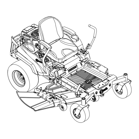
Page 18: Product Overview
Operation Product Overview Operation Controls Note: Become familiar with all of the Figure 4 controls in and Figure 5 before you start the engine and operate the machine. Ignition Switch Located on control panel. The ignition switch is used to start and stop the engine. - Page 19 (see Figure 5). • Models with Exmark 452 cc Engine: The throttle g236810 Figure 6 is located with the choke control. Moving the 1.
-
Page 20: Operating Instructions
Operation Deck Height Adjustment Lever Operating Instructions Located below the RH motion control lever (Figure 4). Think Safety First Pull the lever inward and rearward to raise the cutting Note: Determine the left and right sides of the deck. Allow the handle to move forward to lower the machine from the normal operating position. - Page 21 Operation DANGER DANGER In certain conditions gasoline is extremely In certain conditions during fueling, static flammable and vapors are explosive. electricity can be released causing a spark which can ignite gasoline vapors. A fire or explosion A fire or explosion from gasoline can burn you, from gasoline can burn you and others and cause others, and cause property damage.
-
Page 22: Checking The Engine Oil Level
Operation correct amount of gas stabilizer/conditioner to the neck of the tank. This space at the base of the gas. the filler neck allows gasoline to expand. Do Not fill the fuel tank completely full. Overfilling may Note: A fuel stabilizer/conditioner is most effective result in fuel leakage or damage to the engine or when mixed with fresh gasoline. -
Page 23: Operating The Blades
“SLOW” and position, to engage the blades. “FAST” positions. • For Exmark Engines: Place the throttle in the “FAST” position. Allow the engine to run for a minimum of 15 seconds, then turn the ignition switch to the “OFF”... -
Page 24: The Safety Interlock System
Operation The Safety Interlock System Understanding the Safety Interlock System CAUTION The safety interlock system is designed to prevent the If the safety interlock switches are disconnected engine from starting unless: or damaged the machine could operate • The blades are disengaged. unexpectedly causing personal injury. - Page 25 Operation Check Engine Starting Circuit Chart Note: In the Check Engine Starting Circuit Chart, the state of system item that is bold is being checked in each scenario. System Parking Brake Motion Control Levers Operator Outcome (Blades) Engaged Disengaged Both levers moved in, or either Operator Starter must in seat...
- Page 26 Operation Check Shutdown Circuit Chart Note: The state of system item(s) that is bold is being checked in each scenario. System Engine Parking Motion Control Operator Outcome Brake (Blades) Levers Running idle Disengaged Disengaged Both levers moved Raise off Engine must (1/3 throttle) out (neutral lock), of seat (but...
-
Page 27: Driving Forward Or Backward
Operation Driving Forward or Backward The throttle control regulates the engine speed as measured in rpm (revolutions per minute). Place the throttle control in the Fast position for best performance. Always operate in the Fast (full throttle) position. CAUTION Machine can spin very rapidly by positioning one lever too much ahead of the other. -
Page 28: Stopping The Machine
“FAST” positions. adjustment lever handle inward and let the deck lower down to the desired cut height by slowly • For Exmark Engines: Place the throttle in the decreasing foot pressure allowing the foot lever to “FAST” position. travel rearward. Move the deck height adjustment Allow the engine to run for a minimum of 15 lever outward at the desired height-of-cut. -
Page 29: Positioning The Seat
Operation Stop the machine and move the motion control levers outward to the neutral locked position. Disengage the PTO. Engage the park brake. Stop the engine, remove the key and wait for all moving parts to stop. After adjusting the height of cut, adjust the anti-scalp rollers by removing the nyloc nut. -
Page 30: Changing The Seat Ride Suspension
Operation Move the seat to the desired position and tighten bolts. Tip the seat back to the closed position. • S-Series Units: Push the adjustment lever towards the center of the machine to release the seat adjuster track (Figure 19). g237291 Figure 20 1. -
Page 31: Pushing The Machine By Hand
Operation Move the control lever to the next set of holes. Secure the lever with the hardware. Repeat the adjustment for the opposite control lever. Adjusting the Tilt The motion control levers can be tilted fore or aft for maximum operator comfort. Loosen the upper bolt holding the control lever to the control arm shaft. -
Page 32: Transporting The Machine
Operation DANGER Without the discharge deflector, mulch kit, or entire grass collection system mounted in place, you and others are exposed to blade contact and thrown debris. Contact with rotating mower blade(s) and thrown debris will cause injury or death. •... -
Page 33: Operating Tips
Operation WARNING Loading a machine onto a trailer or truck increases the possibility of tip-over and could cause serious injury or death. • Use extreme caution when operating a machine on a ramp. • Use only a full-width ramp; do not use individual ramps for each side of the machine. - Page 34 Mow at Correct Intervals it immediately with a genuine Exmark replacement Normally, mow every four days. But remember, blade. Only Exmark blades are to be used with this grass grows at different rates at different times. unit. No other blades are approved.
-
Page 35: Maintenance
Unauthorized modifications to the original equipment or failure to use original Exmark parts could lead to serious injury or death. Unauthorized changes to the machine, engine, fuel or venting system, may violate applicable... -
Page 36: Recommended Maintenance Schedule(S)
• Clean the engine and exhaust system area. • Clean the grass and debris build-up from the machine and cutting deck. • Grease all lubrication points. • Clean the air cleaner foam element (more often in dusty, dirty conditions)(Exmark 708cc Every 25 hours engine). -
Page 37: Pre-Maintenance Procedures
Wipe up any excess grease. Engine Maintenance Important: If you are using a machine with an Exmark engine above 5,000 ft (1500 m) for a continuous period, ensure that the High Altitude Kit has been installed so that the engine meets CARB/EPA emission regulations. - Page 38 Exmark Note: Service the air cleaner more often under Customer Care Department at the number(s) extremely dusty, dirty conditions.
- Page 39 Maintenance Install the foam and paper filter onto the air cleaner housing. Install the air cleaner cover and tighten the two knobs. To learn more about the Exmark single-cylinder engine go to http://exmark.com/engines or scan the QR code. g015016 g028323...
- Page 40 Maintenance Check the air cleaner daily or before starting the engine. Check for a buildup of dirt and debris around the air cleaner system. Keep this area clean. Also check for loose or damaged components. Replace all bent or damaged air cleaner components. Note: Operating the engine with loose or damaged air cleaner components could allow unfiltered air into the engine causing premature wear and failure.
-
Page 41: Servicing The Engine Oil
Maintenance To learn more about the Exmark twin-cylinder engine go to http://exmark.com/engines or scan the QR code. g028322 Figure 34 708cc Engine Servicing the Engine Oil Checking the Engine Oil Level–Exmark 452cc Engine Service Interval: Before each use or daily Important: Do not overfill the crankcase with oil and run the engine;... - Page 42 If the level is low, wipe off the area around the oil fill cap, remove cap/dipstick and add oil to the Check the engine oil level. “FULL” mark on the dipstick. Exmark 4-Cycle Premium Engine Oil is recommended; refer to the following information for an appropriate API rating and viscosity.
- Page 43 Stop the engine, remove the key, and wait for all moving parts to stop before leaving the operating position. Change the engine oil filter. Apply a thin film of clean Exmark 4-Cycle Premium Engine Oil to the rubber gasket on the new filter.
- Page 44 Slowly pour approximately 80% of the specified Service Interval: After the first 5 hours oil into the filler tube—use oil recommended in Every 100 hours (change the Checking the Engine Oil Level–Exmark it more often under a 452cc Engine section. heavy load or in high temperatures)(Exmark 708cc Engine).
- Page 45 Maintenance g027799 Figure 42 g029570 Figure 43 Change the engine oil filter. Apply a thin film of clean Exmark 4-Cycle Premium Engine Oil to the rubber gasket on the new filter.
-
Page 46: Servicing The Spark Plug-Exmark 452Cc Engine
Plug-Exmark 452cc Engine Slowly pour approximately 80% of the specified oil into the filler tube—use oil recommended in Service Interval: Every 50 hours the Checking the Engine Oil Level–Exmark 708cc Engine section. Every 100 hours—Replace the spark plug (Exmark 452cc engine). -
Page 47: Servicing The Spark Plug-Exmark 708Cc Engine
Maintenance Removing the Spark Plug–Exmark Check the gap between the center and side 452cc engine electrodes. Set the gap to 0.030 inch (.76 mm). Disengage the PTO and ensure the parking brake is engaged. Installing the Spark Plug–Exmark Stop the engine, remove the key, and wait for all... -
Page 48: Cleaning The Blower Housing
Maintenance Air Gap: 0.030 inch (.76 mm) Removing the Spark Plug-Exmark 708cc engine Disengage the PTO and ensure the parking brake is engaged. Stop the engine, remove the key, and wait for all g027479 Figure 50 moving parts to stop before leaving the operating position. -
Page 49: Fuel System Maintenance
Maintenance More often under dirty conditions. To ensure proper cooling, make sure the grass screen, cooling fins, and other external surfaces of the engine are kept clean at all times. Remove the blower housing and any other cooling shrouds. Clean the cooling fins and external surfaces as necessary. -
Page 50: Charging The Battery
Maintenance Charging the Battery CAUTION If the ignition is in the “ON” position there Removing the Battery is potential for sparks and engagement of components. Sparks could cause an explosion or WARNING moving parts could accidentally engage causing personal injury. Battery terminals or metal tools could short against metal machine components causing Be sure ignition switch is in the “OFF”... - Page 51 Maintenance WARNING Voltage Percent Maximum Charging Reading Charge Charger Interval Incorrect battery cable routing could damage Settings the machine and cables causing sparks. 12.6 or 100% 16 volts/7 Sparks can cause the battery gasses to Charging greater amps explode, resulting in personal injury. Required •...
- Page 52 Maintenance CAUTION Connecting the jumper cables incorrectly (wrong polarity) can immediately damage the electrical system. Be certain of battery terminal polarity and jumper cable polarity when hooking up batteries. Note: The following instructions are adapted g012785 from the SAE J1494 Rev. Dec. 2001 – Battery Figure 54 Booster Cables –...
-
Page 53: Drive System Maintenance
Maintenance Servicing the Fuses Service Interval: As required The electrical system is protected by fuses. It requires no maintenance; however, if a fuse blows, check the component/circuit for a malfunction or short. g007275 Fuse: Figure 56 • Main F1-30 amp, blade-type 1. - Page 54 Maintenance Remove the nuts holding the transaxle support in place (Figure 58). g010254 Figure 59 Right side shown 1. Transaxle drive 4. Screws 2. Oil filter 5. Vent plug 3. Filter guard Carefully clean area around filters. It is important g017660 that no dirt or contamination enter hydraulic Figure 58...
-
Page 55: Mower Maintenance
Maintenance Installing the Hydraulic System Install the transaxle guard. Refer to Figure 58 for Filters the correct torque values for the nuts and bolts. Proceed to the Bleeding the Hydraulic System section. Important: Failure to perform the Bleeding the Hydraulic System procedure after changing hydraulic filters and oil can result in irreparable damage to the transaxle drive system. - Page 56 Note: The machine must be on a level surface for the blades as necessary. If a blade is damaged or the following procedure. worn, replace it immediately with a genuine Exmark replacement blade. For convenient sharpening and Raise the mower deck to the highest height-of-cut replacement, you may want to keep extra blades on position;...
- Page 57 Note: If a bent blade is replaced with a new one and the dimension obtained continues to exceed 1/8 inch (3mm), the blade spindle could be bent. Contact an Authorized Exmark Dealer for service. If the variance is within constraints, move to g014974 the next blade.
-
Page 58: Leveling The Mower Deck
Sharpening the Blades injure or kill you or bystanders. Use a file to sharpen the cutting edge at both ends Always install the original Exmark blades, of the blade (Figure 67). Maintain the original washers and blade bolts as shown. - Page 59 Maintenance Loosen the side-locking nut. Raise or lower the left side of the mower deck by rotating the rear nut. (Figure 71). Note: Rotate the rear nut clockwise to raise the mower deck; rotate the rear nut counter-clockwise to lower the mower deck. g009682 Figure 69 Mower Deck with 2 Blades...
- Page 60 Maintenance Note: Check and adjust the side-to-side blade level if you have not checked the setting; refer to Side-to-Side Leveling. Carefully rotate the blades so they are facing front to rear (Figure 72 and Figure 73). g014634 g009658 Figure 74 Figure 72 Mower Deck with 2 Blades 1.
-
Page 61: Mower Belt Maintenance
Maintenance g005077 Figure 77 1. Mower deck 3. Rear lift rod 2. Hanger bracket g014635 Figure 75 Slide the mower deck rearward to remove the mower belt from the engine pulley. 1. Front support rod 3. Deck bracket 2. Locking nut Slide the mower deck out from underneath the machine. - Page 62 Maintenance Using a spring removal tool, (P/N 92-5771), remove the idler spring from the deck hook to remove tension on the idler pulley and roll the belt off of the pulleys (Figure 78 and Figure 79). WARNING The spring is under tension when installed and can cause personal injury.
-
Page 63: Replacing The Discharge Deflector
Maintenance Attach the front support rod to the mower deck Slide the rod out of the short stand-off, with the clevis pin and hairpin cotter (Figure 75). spring, and discharge deflector . Remove the damaged or worn discharge deflector. Install the mower belt onto the engine pulley; refer to Replacing the Mower Belt. - Page 64 Maintenance g017618 Figure 82 1. Rod and spring 3. Rod, short end, moved assembly installed behind mower bracket 2. Loop end of the spring 4. Short end, retained by installed into the notch in mower bracket. the deflector bracket Secure the rod and spring assembly by twisting it so the short end of the rod can be placed behind the front bracket welded to the deck g017617...
-
Page 65: Cleaning
Maintenance Cleaning Clean all debris from rotating engine air intake screen, around engine shrouding, and exhaust system area. Clean Grass Build-Up Under Wipe up any excessive grease or oil around the Deck engine and exhaust system area. Service Interval: Before each use or daily Clean Debris From Machine Stop engine, wait for all moving parts to stop, and Service Interval: Before each use or daily... -
Page 66: Storage
Storage Storage Restart the engine and run it until it stops. Choke the engine. Start and run the engine until Cleaning and Storage it will not start. Dispose of fuel properly. Recycle pursuant to Stop engine, wait for all moving parts to stop, and local codes. -
Page 67: Troubleshooting
Troubleshooting Troubleshooting Important: It is essential that all operator safety mechanisms be connected and in proper operating condition prior to mower use. When a problem occurs, Do Not overlook the simple causes. For example: starting problems could be caused by an empty fuel tank. The following table lists some of the common causes of trouble. - Page 68 Troubleshooting Problem Possible Cause Corrective Action Engine loses power 1. Engine load is excessive. 1. Reduce the ground speed. 2. Air cleaner is dirty. 2. Clean or replace the air cleaner element. 3. Oil level in the crankcase is low. 3.
-
Page 69: Schematics
Schematics Schematics Electrical Logic Schematic g201257... - Page 71 g011841 Figure 83 This page may be copied for personal use. 1. The maximum slope you can operate the machine on is 15 degrees. Use the slope indicator to determine the degree of slope of hills before operating. Do Not operate this machine on a slope greater than 15 degrees. Fold along the appropriate line to match the recommended slope.
- Page 72 Pack) or Fill in Below Engine Model No. and Spec. No. Model No. Engine Serial No. (E/No) Serial No. ©2018 Exmark Mfg. Co., Inc. Part No. 4503-851 Rev. A 2101 Ashland Ave (402) 223-6375 Beatrice, NE 68310 Fax (402) 223-5489...
Need help?
Do you have a question about the QUEST QZS708GEM50200 and is the answer not in the manual?
Questions and answers
Can you tell me what year this manual is for?
When was it manufactured
one of my outside spindles needs replaced. my question is the pulley nut left-handed threads ?