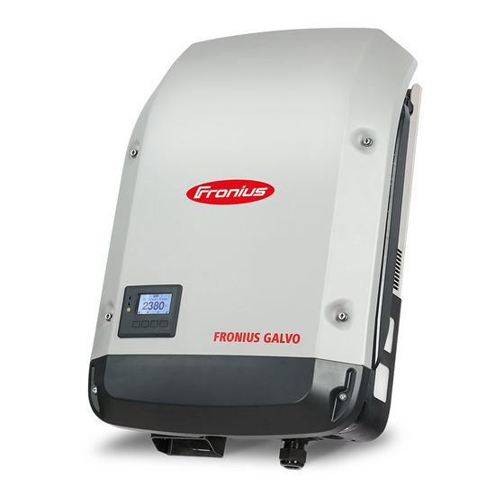
Fronius Galvo Installation Instructions Manual
Grid connected inverter
Hide thumbs
Also See for Galvo:
- Installation instruction (60 pages) ,
- Installation manual (36 pages) ,
- Operating instructions manual (30 pages)
Advertisement
Quick Links
Download this manual
See also:
Installation Manual
Advertisement

Subscribe to Our Youtube Channel
Summary of Contents for Fronius Galvo
- Page 1 / Perfect Charging / Perfect Welding / Solar Energy FIND YOUR OPERATING MANUALS www.fronius.com/galvo-manuals Installation Instruction Fronius Galvo Installation Grid connected inverter 42,0410,1980 012-21022018...
- Page 2 The power stage set, which is enclosed in a separate housing, must only be disconnected from the connection area when in a de-energized state. Maintenance and servicing in the power stage set of the inverter must only be carried out by Fronius- trained service technicians.
- Page 3 The inverter must not be used as part of a three-phase combination, as there is no communication link between the inverters Fronius manufac- Detailed, country-specific warranty terms are available on the internet: turer's warranty www.fronius.com/solar/warranty To obtain the full warranty period for your newly installed Fronius inverter or storage sys- tem, please register at: www.solarweb.com.
- Page 4 Fire Prevention EN CAUTION! Risk of damage to inverters and other live photovoltaic system components due to poor or unprofessional installation. Poor or unprofessional installation can cause overheating of cables and terminal connections and result in arcs. These can cause heat damage, which in turn may lead to fires. Observe the following when connecting AC and DC cables: Tighten all terminals to the torque specified in the operating instructions Tighten all grounding terminals (PE / GND), including free ones,...
- Page 5 Fronius Galvo Installation Help Deutsch English Français Italiano Nederlands Español Deutsch www.fronius.com/QR-link/4204260171DE English www.fronius.com/QR-link/4204260171EN Français www.fronius.com/QR-link/4204260171FR Italiano www.fronius.com/QR-link/4204260171IT Nederlands www.fronius.com/QR-link/4204260171NL Español www.fronius.com/QR-link/4204260171ES Português Magyar Dansk Svensk ελληνικά Türk (Brasil) Português www.fronius.com/QR-link/4204260171PB (Brasil) Magyar www.fronius.com/QR-link/4204260171HU Dansk www.fronius.com/QR-link/4204260171DA Svensk www.fronius.com/QR-link/4204260171SV ελληνικά www.fronius.com/QR-link/4204260171EL Türk...
- Page 6 Fronius Galvo Installation IP 65 > 2000 m max. 2000 m...
- Page 7 2x TX25 110 mm...
- Page 8 min. 3x IP 20 min. 3x Al / St 6 - 8 mm...
- Page 9 Fronius Galvo Installation Help...
- Page 10 Australia - Conduits Pay attention to the correct sealing of the conduits! rigid or flexible...
- Page 11 AC ~ min. 2,5 mm² - max. 16 mm² AC ~ Cu / Al max. Class 4 > 250 mm AC ~ 15 mm > 200 mm Torque (Nm / lbf.in.) → see printing near wire terminal 7,5 Nm...
- Page 12 AC ~ max. C 25 A ≥ 100 mA ΔN § National Standards Type A...
- Page 13 DC = min. 2,5 mm² - max. 26 mm² DC = 7 x 2,5 - 10 mm² 2x TX20 2 x 10 - 16 mm² 15 mm DC = (+) DC = (-) D1 = D2 = D3 D1 = D1 = D1...
- Page 14 ~ 20 mm DC= (+) DC= (-) DC= (+) DC= (-) Fronius Galvo 1.5-1: max. 420 V Fronius Galvo 2.0-1: max. 420 V Fronius Galvo 2.5-1: max. 550 V Fronius Galvo 3.0-1: max. 550 V Fronius Galvo 3.1-1: max. 550 V...
- Page 15 DC = (+) DC = (-) 2x TX20 DC = 1,5 - 1,7 Nm...
- Page 16 1 A / 600 V 41,0007,0187 BASIC Menu / Grounding Settings / Grounding Mode / Negative / Enter...
- Page 17 DATCOM TX20 1,2 Nm...
- Page 18 2,5 Nm 4 x TX25...
-
Page 19: Operation
Operation 2x TX25 2,5 Nm 2x TX25 2,5 Nm... - Page 20 5 0 H z I n t e r n a t i o n a l 5 0 H z * Country Setups 50Hz International 50 Hz Deutschland: Anlagengröße Italia < 11,08 kVA > 13,8 kVA 60Hz International 60 Hz MG50 Microgrid 50 Hz DKA1 Danmark Österreich: Anlagengröße...
-
Page 21: Firmware Update
Firmware Update... -
Page 22: Basic Menu
BASIC Menu BASIC Menu: MPP Tracker 1 M P P T r a c k e r 1 USB Eventlog U S B E v e n t l o g Input Signal I n p u t s i g n a l SMS / Relay S M S / R e l a y Insulation Settings... -
Page 23: Serial Number Sticker For Customer Use
Australia I5 IO3 IO1 GND GND D- CL/0 DRM‘s for RG/0 Australia Serial No. on rating plate Fronius Inverter Operating Instructions Fronius Inverter Installation * Serial Number Sticker for Customer Use, 57 x 20 mm Australia ** DRMs for for Customer Use, 67 x 20 mm... - Page 24 Fronius International GmbH Fronius USA LLC Solar Electronics Division 4600 Wels, Froniusplatz 1, Austria 6797 Fronius Drive, Portage, IN 46368 E-Mail: pv-sales@fronius.com E-Mail: pv-us@fronius.com http://www.fronius.com http://www.fronius-usa.com Under http://www.fronius.com/addresses you will find all addresses of our sales branches and partner firms!


Need help?
Do you have a question about the Galvo and is the answer not in the manual?
Questions and answers