Table of Contents
Advertisement
Quick Links
Advertisement
Table of Contents

Related Manuals for Kanomax CLIMOMASTER 6501 Series


Summary of Contents for Kanomax CLIMOMASTER 6501 Series
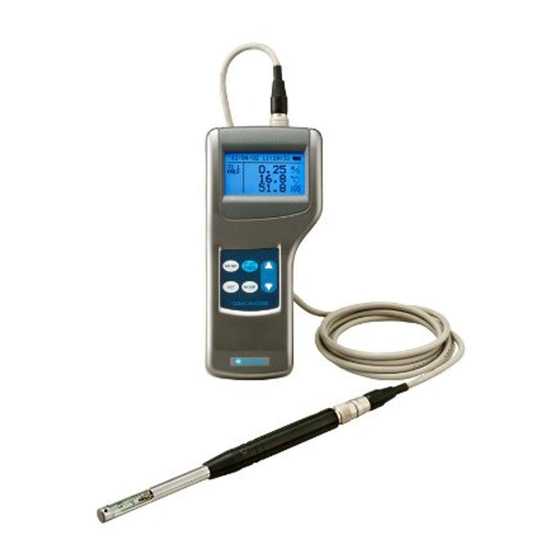
- Page 1 www.lazodecontrol.com +51 960 810 089 ventas@lazodecontrol.com...
- Page 2 List of Components Standard Items MODEL Functions Main Body 6501-00 Main Body with analog 6501-A0 With analog output function output One of Main Body with pressure With pressure measurement 6501-B0 these sensor function Main body with pressure With pressure measurement and sensor and analog 6501-C0 analog output functions...
- Page 3 Important Safety Information The symbols for the warnings used in this manual are defined below: Classifications Danger: To Prevent Serious Injury or Death Warnings in this classification indicate a danger that may result in serious injury or death if not observed. Caution: To Prevent Damage to the Product Warnings in this classification indicate a risk of damage to the product that may void the product warranty if not observed.
- Page 4 Danger Never bring the probe close to a flammable gas atmosphere. The heated sensor may cause a fire or explosion. Forbidden Never touch the sensor. The sensor is heated during operation. Touching the heated sensor may cause burns, and may also damage the sensor itself. Hot surface Do not disassemble or heat the batteries, or put them into a fire.
- Page 5 Do not use or leave the instrument in a high temperature, high humidity or dusty environment. Do not leave this instrument under direct sunlight for a prolonged period. Forbidden The instrument may not function properly out of the specified operating conditions. Do not subject the instrument or the probe to strong impacts.
- Page 6 Do not move the main unit and the probe from a cold place to a warm place quickly. It will cause condensation. Even when used in an environment within the specified operating Forbidden temperature and humidity, a sudden temperature change may cause condensation.
-
Page 7: Table Of Contents
About Compensation ..................... 56 § 14 Probe Directivity (Air Velocity) ............... 57 § 15 Trouble Shooting .................. 59 § 16 Warranty and After Service ..............61 Kanomax Limited Warranty ..................61 § 17 Contact Information ................62 www.lazodecontrol.com +51 960 810 089 ventas@lazodecontrol.com... -
Page 8: Part Names And Functions
§ 1 Part Names and Functions Main Body Pressure Port Pressure port is only available on MODEL6501-B0/-C0. Probe Socket Analog output is only available on MODEL6501-A0/-C0. Analog Output Terminal LCD Display Serial Communication Terminal DC Input Terminal Power Switch Touch Panel Battery Compartment www.lazodecontrol.com... -
Page 9: Touch Panel
Touch Panel MENU Key Enters the Main Menu to select a function. *Press the MENU Key to CANCEL out of the current measurement or settings and return to the Main Menu. Normal Measurement Mode MENUaa1.NORMAL To input duct shape and size aaaaaa2.DUCTaTYPE Calculation Mode aaaaaa3.CALCULATION... -
Page 10: Probe
Probe There are 8 different types of probes available for CLIMOMASTER. The model number and specifications depends on the type of the probe you have. The compatibility feature of the probes allows you to swap out probes freely without having to recalibrate the main unit. -
Page 11: Probe Cable
Probe Cable The probe can be extended by using a probe cable between the main unit and the probe. Main Body Connector Probe Connector Approx.43 Approx.43 Approx.2000 *Unit: mm Extension Rod (Optional) Straight Cable length: Approx.2000 including the rod Approx.130 Approx.50 Approx.230 to 870 *Unit: mm... -
Page 12: Getting Started
§ 2 Getting Started Installing Batteries Backside of the body 1. Press down on the battery cover. 2. Slide the cover until it stops. 3. Lift the cover away from the body. 4. Insert the batteries according to the indicated polarity chart. This instrument requires six (6) AA size batteries that must be of the same type. -
Page 13: Connecting The Probe And The Probe Cable
Connecting the Probe and the Probe Cable This section describes how to connect the probe or the probe cable to the main unit. Make sure that the power is turned OFF when connecting or disconnecting the probe or the probe cable. 1. -
Page 14: Turning On/Off The Power
The power switch to turn the power ON/OFF is located at the side of the instrument. When you turn the power on after connecting the probe/probe cable, a test screen with the Kanomax logo, model, and the version of the firmware will be displayed for a few seconds before it switches to the Normal Mode screen. -
Page 15: Precautions For Measurements
Precautions for Measurements Air Velocity Direction Mark MODEL6531/6541/6561: The probe has its own directivity characteristics. Make sure that the direction mark is facing into the airflow. If you are not sure of the airflow direction, slowly rotate Airflow the probe and select the point where you get the maximum velocity reading. - Page 16 Pressure Do not expose the pressure sensor to more than 75kPa of pressure. Pressure sensor is Excess pressure may cause serious damage to the sensor. only available on MODEL6501-B0/-C0. The operating temperature must be between 5 C and 40 C or 41 and 104 F when measuring pressure.
-
Page 17: Duct Shape / Size Input
Duct Shape / Size Input Before measuring the volumetric flow rate, the duct shape and size settings must be entered. Up to 25 different duct types can be registered in this instrument. Select a duct type from the registered duct types to measure the air flow rate. - Page 18 <To Set Duct Size> Registering a Rectangular Duct aaaaaaaDUCTaTYPE WIDTH and 1.ENTRYaNo.aaaaaaaa1 2.SHAPEaaaaRECTANGLE 3.WIDTHoooooooooo800 press to enter the 4.HEIGHTooooooooo500 5.UNIT(mm/inch)aaamm width and press 6.SAVEaINFO HEIGHT and press . Use to enter the height and press The maximum is 9999mm or 999.9 inch. Registering a Circular Duct aaaaaaaDUCTaTYPE 1.ENTRYaNo.aaaaaaaa1...
-
Page 19: Normal Measurement Normal Mode
§ 3 Normal Measurement NORMAL MODE This is the mode that you will be in, when you first turn on the instrument. In this mode you cannot save any data. The display is updated every 1 second. To move to NORMAL Mode from MENUaa1.NORMAL aaaaaa2.DUCTaTYPE aaaaaa3.CALCULATION... - Page 20 Hold the Reading While measuring (in NORMAL Mode), '12/04/12a15:40:23 ~ Humidity is only press the key to hold the current available on 0.87f TCC1 MODEL6531/6533. reading. This is applicable in both the 25.3e flow rate and pressure measurement Air temperature is 64.1g only available on screens as well.
- Page 21 Setting the Time Constant In NORMAL Mode, you can change the '12/04/12a15:40:23 ~ Humidity is only available on 0.87f Time Constant (TC) by pressing TCC1 MODEL6531/6533. 25.3e Air temperature is 64.1g only available on MODEL6531/6541 Time Constant /6542/6533/6543/ You can select the Time Constant from 1, 5 or 10seconds. 6561.
- Page 22 Changing the Time Constant Application When you first turn on the instrument, the Time Constant is only Pressure is only available on effective for AIR VELOCITY and AIR FLOW in Normal Mode. If you MODEL6501-B0 want to make it effective for AIR TEMPERATURE, HUMIDITY and /-C0.
-
Page 23: Measuring Max, Min, And Mean: Calculation Mode
§ 4 Measuring Max, Min, and Mean: CALCULATION Mode CALCULATION Mode will automatically calculate the maximum, minimum and mean of the measured data. The 1 trial The 2 trial The N trial TRIAL(1) TRIAL(2) TRIAL(N) Sampling Time Measuring Press to enter the Main Menu. Use MENUaa1.NORMAL aaaaaa2.DUCTaTYPE ALCULATION... - Page 24 <Setting the CALCULATION MODE> and press CALCULATE R20000/20000 1.MODE11111111AVERAGE to select AVERAGE or 2.SAMPLING(TIME)0012s 3.SAMPLING(n)110050 INSTANT and press 4.DATA2STORAGE2?22YES 5.SET2TO2START <Setting the SAMPLING TIME> to select CALCULATE R20000/20000 SAMPLING (TIME) and press 1.MODE11111111AVERAGE 2.SAMPLING(TIME)0012s to select SAMPLING TIME 3.SAMPLING(n)110050 4.DATA2STORAGE2?22YES (1 to 999 sec) and press 5.SET2TO2START <Setting the No.
- Page 25 <READY> The instrument is ready for measuring. Humidity is only '12/04/12a15:40:23 ~ available on 0.87f MODEL6531/6533. RDY. Press to change the applied 25.3e N2221 Air temperature is parameters. (Air Velocity, Air Temp, /2250 only available on 64.1g Humidity Flow Rate, Air Temp, MODEL6531/6541 /6542/6533/6543/ Humidity...
-
Page 26: Measurement Of Air Flow Flow Rate Mode
§ 5 Measurement of Air Flow FLOW RATE Mode CLIMOMASTER features an accurate Flow Rate Mode which corresponds to the industry measurement standards such as ASHRAE. SINGLE FLOW RATE Mode This mode is useful for performing a measurement of the airflow of duct (i.e. - Page 27 Air Flow: Air Volume per Time Unit [m /min, m /h, ft /min, ft Air Flow (Q) = Average Air Velocity (U) x Cross Sectional Area (A) Measurement Point r1 r2 r1=0.316R r2=0.548R r3=0.707R r4=0.837R r5=0.949R Rectangular Duct Circular Duct MENUaa1.NORMAL Press to enter the Main Menu.
- Page 28 <Setting the No. TRIAL> to select SINGLE (R20000/20000 SAMPLING(n) and press 1.SAMPLING(TIME)001os 2.SAMPLING(n)110050 3.MEAS.2POINT220010 to select No. TRIAL (1 to 4.DATA2STORAGE2?22YES 5.DUCT2ENTRY2NO.2221 6.SET2TO2START 9999) and press <Setting MEAS. POINT> to select SINGLE (R20000/20000 1.SAMPLING(TIME)001os MEAS. POINT 2.SAMPLING(n)110050 3.MEAS.2POINT220010 to select the number of 4.DATA2STORAGE2?22YES 5.DUCT2ENTRY2NO.2221 MEAS.
- Page 29 <Ready> The ready screen will be displayed. '12/04/12a16:11:59 ~ while pressing --6037a RDY. P 2221 change the entry no. of the duct type. 25.1e N2221 D2223 63.7g C2300 Press to start measuring. Display Icons 1. RDY: Current Status (READY/SAMPLE) 2. P 1: Current Number of Points 3.
-
Page 30: Multi Flow Rate Mode
MULTI FLOW RATE Mode MULTI FLOW RATE is very similar to the SINGLE FLOW RATE MODE, except it adds an additional parameter for the number of locations. This allows you to take several air flow measurements (i.e. traverses) and get a total average, for example measuring flow rate from multiple ducts to get an overall average. - Page 31 <Save the Setting> to select MULTI (R20000/20000 TO START 1.SAMPLING(TIME)001ps 2.SAMPLING(n)110050 3.MEAS./LOC.oo010/010 4.DATA2STORAGE2?22YES 5.DUCT2ENTRY2NO.2221 6.SET2TO2START If you press before saving the settings you will return back to the Main Menu and any setting changes you made will not be saved. <Ready>...
-
Page 32: Store And Recall Measured Data
§ 6 Store and Recall Measured Data Data which can be stored in the memory of the instrument is shown below. What can be Stored Measuring MODEL CALCULATION Mode FLOW RATE Mode Mode Display 6531 6533 Stored V, W V, W V, W Parameters T, H... - Page 33 <Setting the PAGE> to select the page that CALCULATION you would like to recall and press 22222DAPAGEOSET Page Number PAGE:0001 Measured Mode (CALCULATION (A): AVERAGE/(I): INSTANT ) MODE:CALCULATION(A) Measured Date (Year/Month/Day) DATE:2012/04/12 Measured Time (Hour : Minute : Second) TIME:2213:40:53 Number of Trial MEAS./LOC.:2220/2ooo- Duct Shape/Size (For Air Flow Measurement only)
- Page 34 <Setting the CALCULATION RANGE> You can select the range of calculation. If the data range is correct, press to calculate the range of data displayed on the screen. If the range is not correct, press START:00100END:050 NUM.0m/s0000°C000%RH 001000.810025.40064.7 002000.950025.40064.7 003000.980025.60064.9 to select the first number of 004001.050025.70065.1 005001.210025.70065.0...
-
Page 35: Print Out
§ 7 Print Out Preparation for Printing Serial Communication Connect the printer cable to the Serial Terminal Communication terminal located on the side of the instrument to print out measurement data. <Requirements> Printer (optional) Recommended: Seiko Instruments Model DPU-S245 Printer Cable (optional) <Check the BAUD RATE>... -
Page 36: Print Out In Calculation Mode And Flow Rate Mode
Print Out in CALCULATION Mode and FLOW RATE Mode <Measurement and Calculation Mode (CALCULATION)> Press after the measurement and aNEXCALCULATION calculation has been performed to print 102.76f out the result. 081.43f 060.81f <Airflow Measurement Mode (FLOW RATE)> Press after the measurement and aNEXT1FLOW2RATE calculation has been performed to print 106433a... -
Page 37: Print Out Stored Data Single Page
Print Out Stored Data Single Page Press to enter the Main Menu. MENUaa1.NORMAL aaaaaa2.DUCTaTYPE aaaaaa3.CALCULATION aaaaaa4.FLOWaRATE aaaaaa5.DATAaOUTPUT and press aaaaaa6.DATAaCLEAR aaaaaa7.UTILITY aaaaaa8.PRESSUREaZERO DATA OUTPUT to select 1.DISPLAY 2.PRINTER(SINGLE) PRINTER(SINGLE) 3.PRINTER(MULTI) to select the page that you would to print out and press 22222DAPAGEOSET Page Number PAGE:0002... - Page 38 AaaaaPRINT OUTPUT Press to select the contents of the 1.RESULT Print Out. 2.DATA 3.ALL to select from items 1 to 3 and press to print out. Please refer to the printing example shown below. Conditions and Calculation Results Conditions and Stored Data Conditions, Calculation Results and Stored Data Example of Print Out PAGE SET...
-
Page 39: Print Out Stored Data Plural Pages
Print Out Stored Data Plural Pages Press to enter the Main Menu. MENUaa1.NORMAL aaaaaa2.DUCTaTYPE aaaaaa3.CALCULATION aaaaaa4.FLOWaRATE aaaaaa5.DATAaOUTPUT and press aaaaaa6.DATAaCLEAR aaaaaa7.UTILITY aaaaaa8.PRESSUREaZERO to select DATA OUTPUT 1.DISPLAY 3. PRINTER(MULTI) and press 2.PRINTER(SINGLE) 3.PRINTER(MULTI) ooDATAoOUTPUT(MULTI) to select 1.SELECToSTART:o0001 oooooooooENDoo:o0003 1.SELECT and press oooooooooSEToo:oooNO 2.ALLoDATAooooooooNO oooooooooR00020/20000... -
Page 40: Digital Output
§ 8 Digital Output Preparation Serial Communication Terminal You can download the data stored in the CLIMOMASTER to your PC, by connecting the CLIMOMASTER to your PC with the USB cable. Requirements Personal Computer USB Cable (supplied) Communication Software (such as Hyper Terminal for Windows) Connecting PC 1. - Page 41 Transmission of On-Time Data Measured at every 1sec <Enter the Number of Data Needed> 1. Type **** . *Type in the number of data(4 digits) after D . 3. Each data represents 1 second of measurement. If you ask for 20 data, it takes approximately 20 seconds to display.
- Page 42 Transmission of Stored Memory Example <To Download the Duct Setting> 1. Type K the data will be displayed. 3. All stored duct settings (1 through 25) will be downloaded. Output Content Entry No. (Data Location); Width; Height; Diameter; Units of Duct Size Example <To Download the Page Number>...
- Page 43 <To Download the Measuring Condition of Stored Data> **** . *Type in the desired page number( Output Content Measuring Parameter WTH: Flow Rate; Temperature; Humidity Flow Rate; Temperature VTH: Velocity; Temperature; Humidity Velocity; Temperature PRS: Pressure Pressure is only available on B.
-
Page 44: Analog Output
§ 9 Analog Output Analog Output Analog output is only Terminal (Except Humidity; updated every 1sec) available on MODEL6501-A0/-C0. 3. Output Voltage DC 0 to 1V For analog output, you must select one setting from the table below. (There is no analog output for Flow Rate) Conversion Formula Parameter Output Range... - Page 45 Press to enter the Main Menu. MENUaa1.NORMAL aaaaaa2.DUCTaTYPE aaaaaa3.CALCULATION aaaaaa4.FLOWaRATE aaaaaa5.DATAaOUTPUT Press aaaaaa6.DATAaCLEAR aaaaaa7.UTILITY aaaaaa8.PRESSUREaZERO to select aaaaaaaUTILITY oooooooUTILITY 3. ANALOG OUTPUT 1.TIME AJUST 1.TIMEoADJUST 2.UNIT SELECT 2.UNIToSELECT 3.ANALOGoOUTPUT 3.ANALOG OUTPUT Press 4.TC(T.H.P) SET 4.TC(T.H.P)oSET 5.BACKLIGHToON/OFF <To Select Data> and press AaaANALOG OUTPUT Pressure is only 1.OUTPUT2SELECT22VEL.
-
Page 46: Other Settings
§ 10 Other Settings Date MENUaa1.NORMAL Press aaaaaa2.DUCTaTYPE aaaaaa3.CALCULATION aaaaaa4.FLOWaRATE aaaaaa5.DATAaOUTPUT aaaaaa6.DATAaCLEAR press aaaaaa7.UTILITY aaaaaa8.PRESSUREaZERO oooooooUTILITY 1.TIMEoADJUST 2.UNIToSELECT and press 3.ANALOGoOUTPUT 4.TC(T.H.P)oSET 5.BACKLIGHToON/OFF AaaaaTIME2ADJUST *The style of date to select "1. STYLE" or 1.STYLE:222JP displayed on the 2.DATE2:22012/04/12 "2. DATE" and press 3.TIME2:22214:37:27 screen or for printer output depends on... -
Page 47: Units And Baud Rate
Units and Baud Rate <Units Conversion Table> Velocity 1m/s = 196 FPM Temperature T( F) = 1.8×T(°C +32 Flow Rate /h = 35.32ft Press to enter the Main Menu. MENUaa1.NORMAL aaaaaa2.DUCTaTYPE aaaaaa3.CALCULATION aaaaaa4.FLOWaRATE aaaaaa5.DATAaOUTPUT Press aaaaaa6.DATAaCLEAR aaaaaa7.UTILITY aaaaaa8.PRESSUREaZERO oooooooUTILITY 1.TIMEoADJUST and press 2.UNIToSELECT 3.ANALOGoOUTPUT... -
Page 48: Settings For Lcd Backlight
Settings for LCD Backlight MENUaa1.NORMAL Press aaaaaa2.DUCTaTYPE aaaaaa3.CALCULATION aaaaaa4.FLOWaRATE aaaaaa5.DATAaOUTPUT aaaaaa6.DATAaCLEAR Press aaaaaa7.UTILITY aaaaaa8.PRESSUREaZERO oooooooUTILITY to select 1.TIMEoADJUST 2.UNIToSELECT 3.ANALOGoOUTPUT Press 4.TC(T.H.P)oSET 5.BACKLIGHToON/OFF ooooLCDoBACKLIGHT Press 1.BACKLIGHToON to select ooooFORoooooooo01omin BACKLIGHT ON/OFF. Press 2.SAVEoINFO BACKIGHT OFF Backlight is always off. BACKLIGHT ON If you press any button, the backlight will turn on according to the following settings: <Settings for Backlight Lit-Up Time>... -
Page 49: To Delete Data
To Delete Data Press to enter the Main Menu. MENUaa1.NORMAL aaaaaa2.DUCTaTYPE and press aaaaaa3.CALCULATION aaaaaa4.FLOWaRATE to select 1. (delete aaaaaa5.DATAaOUTPUT aaaaaa6.DATAaCLEAR aaaaaa7.UTILITY the selected data only) and press aaaaaa8.PRESSUREaZERO AaaaaDATARCLEAR 1.CLEARLSTART:000001 Ending Page Number 00000000END00:000001 Partial Delete (YES or NO) 00000000SET00:002YES All Delete YES or NO... -
Page 50: To Delete All The Data
To Delete All the Data Press to enter the Main Menu. Use t MENUaa1.NORMAL aaaaaa2.DUCTaTYPE Press aaaaaa3.CALCULATION aaaaaa4.FLOWaRATE aaaaaa5.DATAaOUTPUT aaaaaa6.DATAaCLEAR aaaaaa7.UTILITY aaaaaa8.PRESSUREaZERO AaaaaDATARCLEAR 1.CLEARLSTART:000001 00000000END00:000001 00000000SET00:0020NO 2.ALL2CLEAR0000000NO 000000000R19950/20000 (The number of sampling data that can be stored) AaaaaDATARCLEAR 1.CLEARLSTART:000001 00000000END00:000001 00000000SET00:0020NO Press 2.ALL2CLEAR000000YES... -
Page 51: Contrast Adjustment
Contrast Adjustment If the LCD display of the CLIMOMASTER is dark light, there adjustment dial at the back, bottom of the unit, inside the battery cover. Contrast Adjusting Dial You can adjust the contrast by using a precision screwdriver (-) 0.9 to 1.5mm . -
Page 52: How To Clean A Probe
§ 11 How to Clean a Probe Dust or particles attached to the velocity sensor would alter the amount of heat diffusion, which leads to a less precise reading. Also, deformation or clogging of the protective mesh around the sensor of the probe would also affect the accuracy of the instrument. -
Page 53: Specification
§ 12 Specification CLIMOMASTER Air Velocity Meter Product 6501 Model No. of the Main Body 6541 6561 6542 6551 6552 6543 Model No. of the Probe 6531-21 6533-21 Measuring Object Clean air flow Measuring Range 0.01 to 30.0, 0.01 to 50.0 (6561-21 only) 0.01 to 5.00 0 to 9.99: 0.01 Resolution... -
Page 54: Principle Of Measurement
§ 13 Principle of Measurement Principle of Hot-wire Anemometer The principle of the thermal Probe is Current based on a heated element from which heat is extracted by the colder impact flow. The temperature is kept Cooling constant via a regulating switch. The Wind controlling current is directly -off... - Page 55 Measurement of Wind-Temperature (MODEL 6531/6541/6542/6533/6543/6561) Wind The coefficient of resistance of the temperature sensor has a Wind direct proportional relationship with the temperature. We can measure the wind temperature by adjusting the temperature to the wind-temperature, and measuring its Temp Sensor (Platinum Resistor) coefficient of resistance.
-
Page 56: What Are Discomfort Index (Di) And Dew Point Temperature (Dt)
What are Discomfort Index (DI) and Dew Point Temperature (DT)? What is DI and DT? Discomfort Index (DI) Discomfort Index is an index to show how uncomfortable it is in the summer time. CLIMOMASTER use the formula, shown below, which is used by Meteorological Agencies. -
Page 57: About Compensation
& 21% oxygen concentration). If you wish to use the instrument in an environment other than normal air, you will need to compensate for the characteristics of the gas mixture Kanomax representative for details. Principle of Measurement www.lazodecontrol.com +51 960 810 089 ventas@lazodecontrol.com... -
Page 58: Probe Directivity (Air Velocity)
§ 14 Probe Directivity (Air Velocity) MODEL 6531-21 / 6541-21 / 6561-21 Horizontal Wind Direction Indicator At 5m/s Vertical Wind Direction Indicator At 5m/s www.lazodecontrol.com +51 960 810 089 ventas@lazodecontrol.com... - Page 59 Probe Directivity (Air Velocity) MODEL 6542-21 Horizontal Vertical At 1m/s Probe Directivity (Air Velocity) M O D E L 6 5 3 3 - 2 1 / 6 5 4 3 - 2 1 / 6 5 5 1 - 2 1 / 6 5 5 2 - 2 1 Vertical Horizontal At 1m/s...
-
Page 60: Trouble Shooting
The probe or the probe cable may be damaged. Page 62 Contact your local Kanomax representative for repair or replacement. instrument The probe might be not facing into the wind. reading the correct air... - Page 61 Output check (1) - Print out Problem Possible cause(s) / Solution(s) Reference The printer is not connected properly. Page 34 Confirm the printer connection. The Baud Rate might not be set properly. Check both the instrument and printer Page 46 settings.
-
Page 62: Warranty And After Service
§ 16 Warranty and After Service Kanomax Limited Warranty The limited warranty set forth below is given by KANOMAX JAPAN, Inc. (hereafter X brand anemometer, and its attachment parts including probe and other accessories (hereafter referred to as Your PRODUCT, when delivered to you in new condition in its original container, is... - Page 63 www.lazodecontrol.com ventas@lazodecontrol.com Jr.Salaverry 160 – Magdalena Automatización y Medio Ambiente +51 960 810 089 www.lazodecontrol.com +51 960 810 089 ventas@lazodecontrol.com...
Need help?
Do you have a question about the CLIMOMASTER 6501 Series and is the answer not in the manual?
Questions and answers