GW Instek GOM-802 User Manual
D.c. milli-ohm meter
Hide thumbs
Also See for GOM-802:
- User manual (55 pages) ,
- User manual (19 pages) ,
- User manual (55 pages)

Related Manuals for GW Instek GOM-802


Summary of Contents for GW Instek GOM-802
- Page 1 All manuals and user guides at all-guides.com D.C. Milli-Ohm Meter GOM-802 USER MANUAL GW INSTEK PART NO. 82OM-80200MF1 ISO-9001 CERTIFIED MANUFACTURER...
- Page 2 All manuals and user guides at all-guides.com This manual contains proprietary information, which is protected by copyright. All rights are reserved. No part of this manual may be photocopied, reproduced or translated to another language without prior written consent of the Good Will company. The information in this manual was correct at the time of printing.
-
Page 3: Table Of Contents
SAFETY INSTRUCTIONS ............ 4 Safety Symbols ............ 4 Safety Guidelines ..........5 GETTING STARTED ............8 GOM-802 Characteristics ........9 Key Features ............11 Front Panel Overview ........12 Rear Panel Overview ......... 16 ... -
Page 4: Safety Instructions
GOM-802 in the best possible condition. Safety Symbols These safety symbols may appear in this manual or on the GOM-802. Warning: Identifies conditions or practices that could result in injury or loss of life. -
Page 5: Safety Guidelines
All manuals and user guides at all-guides.com SAFETY INSTRUCTIONS Safety Guidelines Do not place any heavy objects on the GOM-802. General Guideline Avoid severe impact or rough handling that leads to damaging the GOM-802. CAUTION Do not discharge static electricity to the GOM-802. - Page 6 Temperature: 0°C to 40°C (operation) (Note) EN 61010-1:2001 specifies the pollution degrees and their requirements as follows. The GOM-802 falls under degree 2. Pollution refers to “addition of foreign matter, solid, liquid, or gaseous (ionized gases), that may produce a reduction of dielectric strength or surface resistivity”.
- Page 7 All manuals and user guides at all-guides.com SAFETY INSTRUCTIONS Power cord for the United Kingdom When using the GOM-802 in the United Kingdom, make sure the power cord meets the following safety instructions. NOTE: This lead / appliance must only be wired by competent persons...
- Page 8 Please note the information in this manual was correct at the time of printing. However as GW Instek continues to improve its products, changes can occur at any time without notice. Please see the GW Instek website for the latest information and content. Characteristics GOM-802 Characteristics .........
-
Page 9: Getting Started
The ability to choose between high measurement accuracy with 7 samples/sec (full scale at 30000) or high speed measurements with 30 samples/sec (full scale at 3000) allows the GOM-802 the flexibility to fulfill a number of different measurement roles. - Page 10 DUT at a certain temperature. When the temperature coefficient and the required temperature (of the resistance measurement) is keyed in under TC mode, the GOM-802 will display the extrapolated measurement. For automatic testing The GOM-802 has a handler Automatic interface designed for automatic testing.
-
Page 11: Key Features
All manuals and user guides at all-guides.com GETTING STARTED Key Features 30,000 counts. Measurement Range: 30mΩ~3MΩ. 0.05% accuracy. Hi/Lo comparator and limit percentage setting with 20 memory sets. REL, Actual and % value measurements. Manual or Auto-ranging. ... -
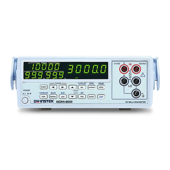
Page 12: Front Panel Overview
All manuals and user guides at all-guides.com GOM-802 User Manual Front Panel Overview Turns On or Off the main Power Switch power. For details about the power up sequence, see page 18. Primary Value Display Shows the primary measurement results. - Page 13 All manuals and user guides at all-guides.com GETTING STARTED Function Control Indicators Indicates when a function key is active. Sense HI and Sense LO terminals. Measurement Terminals Current Source Terminals, Source HI Current Source and Source LO. Terminals Negative Terminal. This terminal has Negative the same potential as earth, but cannot Terminal...
- Page 14 All manuals and user guides at all-guides.com GOM-802 User Manual Sample speed VALUE The REL% key is used to perform a zero adjustment to the test leads or a DUT. Using the shift key will display the measured values as a percentage of the normal value.
- Page 15 Displays the lower limit as as a Lower Limit percentage. Display (LO) Displays the upper limit as a percentage. Upper Limit Display (HI) The interface indicator shows the status Interface mode of the GOM-802. Remote mode Indicator (RMT), Handler mode (HAND) or Scan mode.
-
Page 16: Rear Panel Overview
All manuals and user guides at all-guides.com GOM-802 User Manual Rear Panel Overview Accepts the power cord. AC 100/120V AC Input or 220/230V; 50/60Hz. For the power on sequence, see page Holds the main fuse: Fuse Socket 100/120V: T0.3A 250V;... -
Page 17: Set Up
All manuals and user guides at all-guides.com GETTING STARTED Set Up Tilt Stand 1. Pull handle base away from the casing. Steps 2. Turn handle into any of the preset positions. Stand Position Carry Position... -
Page 18: Power Up
All manuals and user guides at all-guides.com GOM-802 User Manual Power Up 1. Ensure that the correct voltage is lined up with the arrow on the fuse cover on the rear panel. 100V 120V 220V 230V 2. Connect the power cord to the AC Voltage input. -
Page 19: Wire Kelvin Connection
All manuals and user guides at all-guides.com GETTING STARTED Example: Resistance measurement mode 4 Wire Kelvin Connection The GOM-802 uses 4 wire Kelvin connections for Background accurate measurements. Diagram Description Source HI The Source HI carries the measuring current source. It is connected to the + side of the DUT. -
Page 20: Zeroing (Relative Function)
All manuals and user guides at all-guides.com GOM-802 User Manual Zeroing (Relative Function) The Relative function is used to perform a zero Background adjustment on the test leads. After the Relative value is pre-set, each measurement that is displayed is equal to the actual value – relative preset value. -
Page 21: Measurement
All manuals and user guides at all-guides.com MEASUREMENT EASUREMENT Overview Measurement Overview .......... 22 Resistance Resistance Measurement ........23 Select the Resistance Range ........24 Rate Select Measurement Rate ........25 Trigger Using the Trigger Function ........25 Compare Compare Function ..........26 Save Compare Settings .......... -
Page 22: Measurement Overview
All manuals and user guides at all-guides.com GOM-802 User Manual Measurement Overview The Measurement chapter refers to the measurements Background listed below. For measurements using the Handler or Scan interfaces, see page 36. Comparison function TEMP Measurement type COMP Temperature sensor... -
Page 23: Resistance Measurement
All manuals and user guides at all-guides.com MEASUREMENT Resistance Measurement 1. Select the Resistance function. TEMP Press SHIFT + COMP access the main function mode. Press the Up and Down arrow keys to select resistance measurement mode (shown above). There are three different modes: (resistance), (temperature) (temperature compensation) -
Page 24: Select The Resistance Range
All manuals and user guides at all-guides.com GOM-802 User Manual Select the Resistance Range The resistance range can be used with normal resistance Background measurement as well as the temperature compensation function. Press the Up and Down arrow keys Auto Range to manually select the resistance range. -
Page 25: Select Measurement Rate
For detailed specifications, please see the specifications on page 49. Note Using the Trigger Function The GOM-802 can use internal or manual triggering for Background the resistance, temperature and temperature compensation measurement modes. External triggering is only supported with the Handler and Scan modes. -
Page 26: Compare Function
All manuals and user guides at all-guides.com GOM-802 User Manual The EXT indicator will be lit when the manual trigger is active. Press the MANUAL TRIG 2. Manually Triggering each time you want to start a single Measurements measurement. The EXT indicator will be lit when the manual trigger is active. - Page 27 All manuals and user guides at all-guides.com MEASUREMENT The GO, HI or LO indicators will light up for each measured value that is compared to the upper and lower limits. 1. Select the compare function TEMP Press COMP to access the compare mode, as shown above.
-
Page 28: Save Compare Settings
All manuals and user guides at all-guides.com GOM-802 User Manual Use the Up and Down arrow keys to edit the value of the selected digit. Range 000~999 Press ENTER to confirm the setting. 4. LO limit setting Press LOW to set the LO percentage limit. -
Page 29: Recall Compare Settings
20 memory locations. If these values are not saved, the settings will be lost after exiting Compare mode. Up to 20 Normal, High, Low settings can be saved on the GOM-802. 1. Select Recall mode RECALL... -
Page 30: Buzzer Function
All manuals and user guides at all-guides.com GOM-802 User Manual 2. Select memory location Use the Left and Right arrow keys to select a digit. The selected digit will flash. Use the Up and Down arrow keys to edit the value of the selected digit. -
Page 31: Display As Percentage
All manuals and user guides at all-guides.com MEASUREMENT Pressing SHIFT before pressing ENTER will exit the Note Buzzer function settings. Display as Percentage In the compare function, the measured value can be Background displayed as a percentage of the Normal value rather than the actual value. -
Page 32: Temperature Measurement
All manuals and user guides at all-guides.com GOM-802 User Manual Relative Function The Relative function is used to perform a zero Background adjustment on the test leads or the resistance of the DUT. After the Reference value is pre-set, each measurement that is displayed is equal to the actual value –... -
Page 33: Relative Function
All manuals and user guides at all-guides.com MEASUREMENT Press the Up and Down arrow keys to select the ˚C measurement mode (shown above). There are three different modes: (resistance), (temperature) (temperature compensation) mode. Press ENTER to confirm 2. Temperature mode display appears. -
Page 34: Temperature Compensation
All manuals and user guides at all-guides.com GOM-802 User Manual Temperature Compensation If the resistance of a DUT at a particular temperature is Background needed the compensation function can be used. This function can simulate the resistance of a DUT at a desired temperature. -
Page 35: Select The Resistance Range
All manuals and user guides at all-guides.com MEASUREMENT Sensor Connection: 3. Temperature compensation connection. DUT connection 4 Wire: Select the Resistance Range Background The resistance range can be selected when using the temperature compensation function. Press the Up and Down arrow keys Auto Range to manually select the resistance range... -
Page 36: Handler/Scan/ Interface
All manuals and user guides at all-guides.com GOM-802 User Manual ANDLER/SCAN/ INTERFACE Handler Handler Overview ..........37 Scan Scan Overview ............38 Scan Setup ............. 38 Scan Output ............41 Interface Configure Interface ..........42 Configure GPIB Interface ........42 Configure RS-232 Interface ........ -
Page 37: Handler Overview
All manuals and user guides at all-guides.com HANDLER/SCAN/ INTERFACE Handler Overview The Handler Interface is used to help bin components Background based on the Go-NoGo comparator function test. There are 6 TTL outputs and one TTL input. The Handler interface can only be used with the resistance measurement and compare measurement modes. -
Page 38: Scan Overview
All manuals and user guides at all-guides.com GOM-802 User Manual Scan Overview The Scan function is used to automatically bin groups of Background up to 100 components. The scan function, unlike the handler interface must first be activated using the panel keys. - Page 39 All manuals and user guides at all-guides.com HANDLER/SCAN/ INTERFACE 2. Select the resistance function. TEMP Press SHIFT + COMP access the main function mode. Press the Up and Down arrow keys to select the resistance measurement mode (shown above). There are three different modes: (resistance), (temperature) (temperature compensation)
- Page 40 All manuals and user guides at all-guides.com GOM-802 User Manual Count units 30~30,000 Press ENTER to confirm. 7. The Ready Display appears After the Ready indicator is shown it is not possible to make any changes to the compare Note function or range.
-
Page 41: Scan Output
All manuals and user guides at all-guides.com HANDLER/SCAN/ INTERFACE Scan Output The timing diagrams for the scan output under different Background conditions are shown below. Ready message displayed… After the MANUAL TRIG key is pressed… Relay Pass High Clock STRB Scan channel 1. -
Page 42: Configure Interface
GOM-802 User Manual Configure Interface The RS-232 and GPIB interfaces are factory installed Overview options for remote control of the GOM-802. The remote control interfaces allow the GOM-802 to be programmed for automatic testing. For more information on the remote control programming, please see the GOM-802 programming manual. -
Page 43: Configure Rs-232 Interface
No loop or parallel connection Configure RS-232 Interface The GOM-802 uses an RS-232C connection for remote Background control. When connecting to a PC ensure the correct baud rate, parity, data bits, stop bit and data control settings are used. -
Page 44: Interface Function Check
Operation *idn? This should return the Manufacturer, Model number, and Firmware version. GW. Inc, GOM-802 , FW1.00 If you do not receive a proper response from the Meter, Function Check please check if the power is on, the GPIB address/RS232 Errors baud rate is correct, and all cable connections are active. -
Page 45: Faq
All manuals and user guides at all-guides.com ● What are the different measurement speeds? ● The GOM-802 performance does not match the specifications. What are the different measurement speeds? There are two measurement speeds for both resistance and temperature measurement. At 30,000 counts the measurement speed is 7 readings/s, at 3,000 counts the measurement speed is 30 readings/s. -
Page 46: Appendix
All manuals and user guides at all-guides.com GOM-802 User Manual PPENDIX Fuse Replace the AC source fuse ........47 Replacement Temperature Reference Temperature Table ......... 48 Measurement RTD SensorsTemperature ........49 Optional Platinum Sensor........49 Specifications Resistance Measurement ........51 Temperature Measurement ........ -
Page 47: Fuse Replacement
All manuals and user guides at all-guides.com APPENDIX Fuse Replacement Replace the AC source fuse 1. Remove the power cord. Steps 2 2 0 2. Remove the fuse socket using a flat screwdriver. 2 2 0 3. Replace the fuse in the holder. 2 2 0... -
Page 48: Temperature Measurement
All manuals and user guides at all-guides.com GOM-802 User Manual 4. Ensure the correct line voltage is lined up with the arrow on the fuse holder. Insert the fuse socket. 2 2 0 2 2 0 100V/120V TT0.3A 250V Rating 220V/230V T0.25A 250V... -
Page 49: Measurement Rtd Sensorstemperature
All manuals and user guides at all-guides.com APPENDIX RTD Sensors Resistive Thermal Devices (RTDs) are commonly used as Overview temperature sensors. RTDs change resistance linearly over a specific range of temperature. The table below shows some of the inherent features of RTDs compared to thermocouples. - Page 50 All manuals and user guides at all-guides.com GOM-802 User Manual PT-100 sensor are listed below: Ω @ 0˚C Type Standard Alpha Beta Delta PT-100 ITS90 0.003850 0.10863 1.49990 100Ω Example—Calculating the resistance of a PT-100 Temperature Calculation Example RTD at 100˚C (T). The following R Ω...
-
Page 51: Specifications
All manuals and user guides at all-guides.com APPENDIX Specifications The specifications are applicable under the following Conditions conditions: Background A 1-year calibration cycle. An operating temperature of 18 to 28 ˚C (64.4 to 82.4˚F). Relative humidity not exceeding 80%. ... -
Page 52: Temperature Measurement
All manuals and user guides at all-guides.com GOM-802 User Manual Measurement Four-terminal method. Auto-ranging Provided. Over input range “OL” indication Maximum Applied 30m~3Ω range: 30VpDC voltage Other range: 100VpDC Comparator 20 sets of comparator status can be selected. Buzzer mode... -
Page 53: Interface
All manuals and user guides at all-guides.com APPENDIX Interface Handler interface* Signal: START TTL input Signal: LOW, HIGH, FAIL, PASS, EOT, READY total 6 TTL outputs. (This function is valid only under the resistance measurement mode and the compare mode is enabled.) Scan* Signal: READY, PASS, LOW, HIGH, CLOCK, STRB total 6 TTL outputs. -
Page 54: Declaration Of Conformity
All manuals and user guides at all-guides.com GOM-802 User Manual Declaration of Conformity GOOD WILL INSTRUMENT CO., LTD. declare, that the below mentioned product Type of Product: DC Milliohm Meter Model Number: GOM-802 are herewith confirmed to comply with the requirements set out in the... -
Page 55: Index
All manuals and user guides at all-guides.com Index NDEX Buzzer PT-100 sensor temperature calculation ..49 setting ............... 30 Rate Characteristics ............ 9 setting ............... 25 Compare function Rear panel overview ........16 setting ............... 26 Reference temperature table ..... 48, 50 Declaration of conformity .......
Need help?
Do you have a question about the GOM-802 and is the answer not in the manual?
Questions and answers