Table of Contents
Advertisement
Quick Links
Installation Instructions
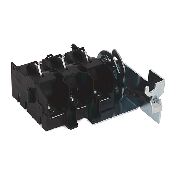
Universal Disconnect Switch Installation Instructions (30A, 60A, 100A)
(Cat 1494U-D30; 1494U-D60; 1494U-D100; Series A)
WARNING: To prevent electrical shock, disconnect from power source before installing or servicing. Follow NFPA 70E requirements. Install in suitable enclosure. Keep free from
contaminants.
Installation, adjustments, putting into service, use, assembly, disassembly, and maintenance shall be carried out by suitably trained personnel in accordance with applicable code of
practice. In case of malfunction or damage, no attempts at repair should be made. The product should be returned to the manufacturer for repair. Do not dismantle the product.
WARNING: The following procedures are critical to the proper operation of the disconnect handle and switch. Failure to follow these steps can result in damage to the equipment and/or
serious injury or death to the operator.
Tools Needed: 7/16" Nut Driver, 5/16" Nut Driver, Hammer, Center Punch, File, T27 Torx Driver, Phillips Screwdriver, 11/64" Drill Bit, Needlenose Pliers
Table of Contents
Installation Guide............................................................................................................................................................................. 2
Rod and Cable Operated Disconnect Switch Location.................................................................................................. 2
Rod Operated Switch Installation.......................................................................................................................................... 3
Handle Installation.................................................................................................................................................................. 3
Connecting Rod Installation................................................................................................................................................ 3
Rod Adjustment Procedure................................................................................................................................................. 4
Cable Operated Switch Installation...................................................................................................................................... 5
Handle and Cable Mechanism Installation..................................................................................................................... 5
Cable to Switch Mechanism Installation......................................................................................................................... 6
Cable Adjustment Procedure.............................................................................................................................................. 7
Enclosure Without Handle Cutout............................................................................................................................................. 8
Door Catch Bracket Installation.................................................................................................................................................. 9
Trailer Fuse Block and Phase Barrier Installation................................................................................................................10
Auxiliary Contact Installation.....................................................................................................................................................11
Line Terminal Adapter Installation..........................................................................................................................................12
Electrical Interlock Installation..................................................................................................................................................12
Fuse Clip and Fuse Installation.................................................................................................................................................13
Protective Cover Installation.....................................................................................................................................................14
Bulletin 1494U Disconnect Switch Component Accessory List....................................................................................15
Page
Advertisement
Table of Contents


Need help?
Do you have a question about the 30A and is the answer not in the manual?
Questions and answers