Table of Contents
Advertisement
Quick Links
Advertisement
Table of Contents

Related Manuals for Intellijel mVCF


Summary of Contents for Intellijel mVCF
- Page 1 µVCF Manual µVCF State Variable Filter Manual Revision: 2018.09.13 ...
- Page 2 µVCFManual Table of Contents Table of Contents Compliance Installation Installing Your Module Overview Features Front Panel Controls Inputs and Outputs Instructions Technical Specifications Page 1 ...
- Page 3 (2) this device must accept any interference received, including interference that may cause undesired operation. Changes or modifications not expressly approved by Intellijel Designs, Inc. could void the user’s authority to operate the equipment. Any digital equipment has been tested and found to comply with the limits for a ...
- Page 4 Installation Intellijel Eurorack modules are designed to be used with a Eurorack-compatible case and power supply. We recommend you use Intellijel cases and power supplies. Before installing a new module in your case, you must ensure your power supply has a free ...
- Page 5 Eurorack case. Ensure the red stripe on the cable lines up with the -12V pins on the bus board. On Intellijel power supplies the pins are labelled with the label “-12V” and a thick white stripe: ...
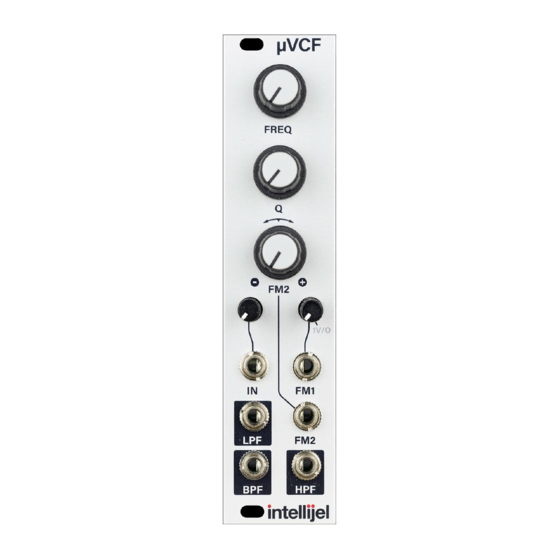
- Page 6 µVCFManual Overview The µVCF state variable filter features three simultaneous filter outputs: a 2-pole 12 dB/octave low pass, a 2-pole 12 dB/octave high pass, and a 1-pole bandpass. It tracks 1 V/octave pitch input over a wide range and can be used as a low-distortion sine VCO when self-resonating. This is another great David Dixon design offering a very clean and precise filter.
- Page 7 µVCFManual Front Panel Controls FREQ - Sets the cutoff frequency of the filter. The knob position is combined with the FM1 and FM2 inputs. 2. Q - Sets the resonance of the filter. 3. FM2 - Controls the amount and polarity of the FM2 input. The input passes unmodified when the knob is fully ...
- Page 8 µVCFManual Instructions Start by plugging the signal that you want to be filtered into the IN input and turn up the Input Attenuator until the signal reaches the desired volume level. Then, one of the LPF, BPF, or HPF outputs and connect that to your VCA or main output.
Need help?
Do you have a question about the mVCF and is the answer not in the manual?
Questions and answers