Bowflex TreadClimber TC200 Assembly & Owners Manual
Hide thumbs
Also See for TreadClimber TC200:
- User manual ,
- Assembly & owners manual (72 pages) ,
- Troubleshooting manual (8 pages)

Related Manuals for Bowflex TreadClimber TC200


Summary of Contents for Bowflex TreadClimber TC200
- Page 1 TC200 ASSEMBLY / OWNER’S MANUAL Manual en Español Latino Americano: www.support.nautilus.com...
-
Page 2: Table Of Contents
Welcome to the Bowflex TreadClimber cardio machine! ® ® You’re about to experience an incredible workout that can help you lose weight and reshape your entire body so you’ll look and feel better than ever Table of Contents Important Safety Instructions ......... 3 Initial Setup ............ -
Page 3: Important Safety Instructions
Important Safety Instructions When using an electrical appliance, basic precautions should always be followed, including the following: This icon means a potentially hazardous situation which, if not avoided, could result in death or serious injury. Obey the following warnings: Read and understand all Warnings on this machine. for future reference. - Page 4 Before using this equipment, obey the following warnings: Important Safety Instructions Read and understand all Warnings on this machine. If at any time the Warning stickers become loose, unreadable or dislodged, contact Nautilus Customer Service for replacement stickers. To reduce the risk of electrical shock or unsupervised usage of the equipment, always unplug the power cord from the power cord in a secure location.
- Page 5 • • • • Use this machine only for its intended use as described in this manual. Do not use attachments not recommended by the manufacturer. • been given supervision or instruction concerning use of the appliance by a person responsible for their safety. Keep children under the age of 14 away from this machine.
-
Page 6: Safety Warning Labels And Serial Number
Safety Warning Labels and Serial Number CAUTION manual before using. WARNING! all Warnings. • Inspect product before use. Do not use if any parts are in need of repair. • Keep children and pets away from this machine at all times. •... -
Page 7: Grounding Instructions
Grounding Instructions Safety Warning Labels and Serial Number The electrical wiring must comply with all applicable local and provincial standards and requirements. Incorrect connection of the equipment-grounding conductor can result in a risk of electric shock. Consult a licensed electrician if outlet, have a correct outlet installed by a licensed electrician. - Page 8 Specifications / Before Assembly Maximum User Weight: Power Requirements: 62.5” (158.8 cm) Maximum Inclined Treadle Height: Assembled Weight: 55” (139.7 cm) 31.5” (80 cm) Before Assembly into consideration the height of the user and the maximum inclined height of the treadles. Basic Assembly •...
-
Page 9: Parts
Parts ( 2 BOXES ) Box 1 Item Description Item Description Pivot Cover Safety Key Hardware Card Shock Document Kit Motor Cover Power Cord Box 2 Item Description DO NOT CUT the Shipping Strap ( * ) or Shipping Zip-Tie ( ** ) on the Treadle Assembly until instructed. - Page 10 Hardware / Tools Hardware Item Description Item Description Note: after the proper assembly of your machine. Tools Included Not Included 5 mm 13 mm Assembly / Owner’s Manual...
- Page 11 Assembly Some components of the machine can be heavy or awkward. Use a second person when doing the assembly steps involving these parts. Do not do steps that involve heavy lifting or awkward movements on your own. 1. Attach the Transport Handle and Release the Pull Cable from the Back of the Base Assembly Note: 5 mm Assembly / Owner’s Manual...
- Page 12 2. Cut open the end of Box 2 and move the Treadle Assembly onto the Base Assembly Some components of the machine can be heavy or awkward. Use a second person when doing the assembly steps involving these parts. Do not do steps that involve heavy lifting or awkward movements on your own. DO NOT CUT the Shipping Strap or Shipping Zip-Tie on the Treadle Assembly until instructed.
- Page 13 3. Cut and Remove the Shipping Strap (*) and then Secure the Treadle Assembly to the Base Assembly 13 mm Assembly / Owner’s Manual...
- Page 14 4. Attach the Pull Cable to the Lower Input/Output Cable and Route It through the Right Side of the Base Assembly Note: Assembly / Owner’s Manual...
- Page 15 5. Route the Lower I/O Cable through the Right Upright Note: Assembly / Owner’s Manual...
- Page 16 6. Attach the Uprights to the Base Assembly Note: 5 mm Assembly / Owner’s Manual...
- Page 17 7. Connect the Cables and Attach the Console Assembly to the Handlebar Assembly Note: hands being caught or pinched. 5 mm Assembly / Owner’s Manual...
- Page 18 8. Attach the Console / Handlebar Assembly to the Uprights Note: Do not crimp the Cables. 5 mm Assembly / Owner’s Manual...
- Page 19 9. Attach the Shocks to Uprights and then Treadles Note: The Treadles do not have a locking mechanism and can move freely. Take care not to allow harm or injury to occur when lifting the Treadles. 5 mm Assembly / Owner’s Manual...
- Page 20 10. Attach the Motor Cover to the Base Assembly Note: Assembly / Owner’s Manual...
- Page 21 11. Attach the Side Covers to the Treadle Assembly Note: Do not fully tighten until all hardware has been installed. Assembly / Owner’s Manual...
- Page 22 12. Attach the Pivot Covers to the Treadle Assembly Note: Do not fully tighten until all hardware has been installed. Assembly / Owner’s Manual...
- Page 23 13. Pivot the Rear Cover onto the Treadle Assembly and Install the Hardware Note: Assembly / Owner’s Manual...
- Page 24 14. Cut the Shipping Zip-Tie from between the Treadles Assembly / Owner’s Manual...
- Page 25 15. Connect Power Cord to Treadle Assembly Note: ® cause the circuit to trip. 16. Final Inspection Inspect your machine to ensure that all fasteners are tight and components are properly assembled. Assembly / Owner’s Manual...
-
Page 26: Moving Your Machine
Adjustments Moving Your Machine ® Adjustments Your machine can be rolled on the transport wheels to a new location. Lower your machine Do not use the uprights, handlebars, or the Console to lift or move the machine. Injury to you or damage to the machine can occur. The machine may be moved by one or more persons depending on their Place the machine on a clean, hard, level surface, free from unwanted material or other objects that may hamper your ability to move freely. -
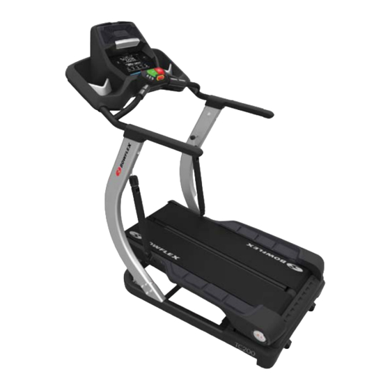
Page 27: Features
Features Safety Key Port Console Handlebars Easy Step Shock Leveler Side Foot Support Platform Power Switch Assembly / Owner’s Manual... - Page 28 Console USER ENTER Program buttons Just Walk Calorie Goal Time Goal Distance Goal Interval PROGRAMS STOP Quick Speed buttons START Speed buttons PAUSE User button Active User display Increase ( ) / Decrease ( ) buttons ENTER button Left ( ) / Right ( ) buttons Program buttons Zone Indicator Light START button...
- Page 29 STOP/PAUSE button Speed buttons (Increase and Decrease) Quick Speed buttons (Increase and Decrease) Console Display Workout Segment Display Smart icon ® display Goal display Current Interval Mode Interval Workout Count Active Workout Program display program. Goal display Workout Segment display USB icon Bluetooth Smart icon...
- Page 30 Heart Rate display shown as solid. Heart Rate Zone Note: Burn display Note: Drink display “+ 500” icon Fitness Score display will be displayed to show the increase in the score. Note: Current Interval Mode Interval Workout Count Speed display Today’s Awards display also provided at the end of the workout.
- Page 31 Burn Rate display USB Charging to operate the Device and charge it at the same time. Connectivity on your fitness machine Note: Software Fitness App “Bowflex TreadClimber™” to make hitting your daily calorie goal easier than ever! Note: Assembly / Owner’s Manual...
- Page 32 Easy Step™ Shocks machine uses Easy Step ® intense workout. easy step Do not change the intensity settings of the Shocks during a workout. Stop the workout and step off the machine before you adjust the Shocks. Note: ting dial toward the Minimum setting or increase the belt speed. It may be helpful to note your dial setting for future reference when there are multiple users of the machine.
- Page 33 Remote Heart Rate Monitor range. Note: OwnCode chest If you have a pacemaker or other implanted electronic device, consult your doctor before using a wireless chest strap or other telemetric heart rate monitor. Chest Strap Using the provided heart rate transmitter chest strap lets you monitor your heart rate at any time during your workout. should be used for reference only.
- Page 34 Contact Heart Rate Sensors • hand movement while in contact with the sensors can also produce interference. • Calluses and hand lotion may act as an insulating layer to reduce the signal strength. • • Heart Rate Calculations using an age related formula. Assembly / Owner’s Manual...
- Page 35 Fat-Burning Target Heart Rate Note: Assembly / Owner’s Manual...
- Page 36 Fitness Basics Frequency ® ® Consistency workout times unless it is absolutely necessary. ® Apparel ® • • • Do not wear loose clothing or jewelry. This machine contains moving parts. Do not put fingers, feet, or other objects into moving Always wear rubber soled athletic shoes when you use this machine.
- Page 37 toward the chest. Place the hands around the shin and pull keeping the knee bent. Hold onto a wall for balance with one Dynamic Twist side and then the other side as far as comfortably possible. Each repetition of the sequence should take 1 to 3 seconds. times to the start position.
- Page 38 Dynamic Side Reach other hand to the opposite side. Use the other arm to support Workouts of breath, or feel faint. Contact your doctor before you use the machine again. Use the values calculated or measured by the ® Steady State workouts Interval Training workouts •...
- Page 39 Afterburn Rate hours afterwards. Workout Schedule Beginner Week 3 Week 4 Steady State Steady State Steady State Steady State Steady State Steady State Steady State Workout 3 Steady State Steady State Steady State Intermediate Week 3 Week 4 Steady State Steady State Steady State Steady State...
- Page 40 Workout Log Date Shock Distance Time Calories Average Setting Speed Easy Step Shock label ™ (for reference only) Assembly / Owner’s Manual...
- Page 41 Cool-Down * ® Lying Leg Raise not round the spine. the stretch for 10 to 30 seconds. Lie on the other side and knees close together. Seated Twist the upper body as far as comfortably possible to one side. the other side. body.
- Page 42 Place the ball of one foot on the edge of a step or staircase. Place the other foot slightly in front. Lower the heel of the comfortably possible. Each repetition of the sequence should Assembly / Owner’s Manual...
-
Page 43: Operations
Operations Before You Start Place the machine on a clean, hard, level surface, free from unwanted material or other objects that may hamper your ability to machine. Shocks. Note: Put the power cord alongside the machine, out of your way when you dismount the machine. Avoid stepping on the power cord and plug. -
Page 44: Initial Setup
Power Up / Idle Mode The belts will only move after a 3 second, audible beep countdown. Shut Off (Sleep Mode) Initial Setup Note: • Gender • Display Units • Weight • Erase Workouts rate information. Assembly / Owner’s Manual... -
Page 45: Workout Programs
Note: Note: been erased. Workout Programs they deactivate showing only what remains to complete the workout. Just Walk Note: Display. Calorie Goal Note: Assembly / Owner’s Manual... - Page 46 Time Goal during a workout. Note: Distance Goal Interval Note: Note: seconds for the SPEED part and 90 seconds for the SLOW part. Starting a Workout 2. Straddle the belts and stand on the Side Foot Support Platforms. Put the Safety Key into the Safety Keyhole and clip the Safety Key cord to your clothing.
-
Page 47: Pausing Or Stopping
Yellow Orange Cardiovascular Performance Changing the Walking Belt Speed increments. Pausing or Stopping a Workout Note: display the workout results. outlet and machine AC input. Place the power cord in a secure location. Fitness Score Display Assembly / Owner’s Manual... - Page 48 Note: based on the User Profile will be used to calculate the score. Note: only be compared to your previous scores and not to other User Profiles. User Fitness Level Based on Fitness Score excellent good high average average low average poor excellent good...
- Page 49 Awards multiple workouts. • Started Workout • For every 100 calories burned • Completed Workout • Worked out 3 days in a row • Worked out 5 days in a row provided with the workout results.. Workout Complete / Results Note: If the Console does not receive any further input after 5 Assembly / Owner’s Manual...
-
Page 50: Machine Settings Mode
Machine Settings Mode machine. Note: Note: Note: Assembly / Owner’s Manual... - Page 51 Note: Mode screen. Note: Assembly / Owner’s Manual...
-
Page 52: Maintenance
Maintenance done. Worn or damaged components must be repaired or replaced immediately. Only manufacturer supplied components can be used to maintain and repair the equipment. To reduce the risk of electrical shock or unsupervised usage of the equipment, always unplug the power cord from secure location. - Page 53 NOTICE: spray lubricant or a petroleum based product as this could seriously impact performance. Note: if necessary. 3. Connect the power cord back into the machine and then into the wall outlet. 4. Stay to one side of your machine. 5.
- Page 54 Walking Belt Alignment Adjusting the Walking Belts – Note: Do not turn the bolts counterclockwise when you adjust the belt alignment. Belt Tension Check – Note: Assembly / Owner’s Manual...
- Page 55 Heart Rate Chest Strap Battery Replacement Do not perform this procedure outdoors or in moist or wet locations. and battery. CR2032 facing up. at approved recycling centers. 5. Inspect your chest strap to ensure function. Assembly / Owner’s Manual...
- Page 56 Maintenance Parts Shock Power Cord Safety Key Strap Cover Left Upright Shock Pivot Cover Motor Cover Left Side Cover Handle Assembly / Owner’s Manual...
- Page 57 Maintenance Parts (Treadle Assembly) Drive Motor Screw Assembly / Owner’s Manual...
- Page 58 Troubleshooting Things to Check Solution Outlet Power cord not plugged in Power switch turned off Switch will light up red to indicate power is present. Safety key not plugged in If problem persists Contact Customer Service. Speed displayed is not accurate Display set to wrong unit of Heart rate not displayed while Moisten skin contact area on the chest strap.
- Page 59 Things to Check Solution Safety key Emergency Stop Procedure in Safety Warn Motor overload power down to protect motor. Consult belt lubrication schedule to determine Outlet Outlet may not have enough power available for the machine due to other machine. Safety Key Insert Safety Key into Safety Key Port on Console.
- Page 60 Bowflex™ Body Weight Loss Guide Introduction and Overview • Lose weight and get lean • Improve your health and wellness • Increase your energy and vitality in your chest, become short of breath, or feel faint. Contact your doctor before you use the machine again. Use the values calcu- mation and should be used for reference only.
- Page 61 • • • Cooked vegetables instead of salad • Eat your calories • and sometimes it will pass. If your goal is muscle gain or strength: • needs in order to gain muscle and strength. • also a great option. Meal Plan Overview calories if needed.
- Page 62 Breakfast Snack #1 smart rich fruit protein carb carbs smart protein carb veggies Lunch Snack #2 healthy smart protein carb smart protein carb veggies Dinner healthy smart protein carb veggies Assembly / Owner’s Manual...
- Page 63 Breakfast Options Smart Carb Cook Plain oats Nuts and milk bread and top with 1 slice of tomato. Yogurt Power Parfait Chopped fruit of your choice with fruit. Sprinkle with 1 serving nuts cinnamon. On the Go PB & Apple Sand- Sliced apple Peanut butter wich...
- Page 64 Snack Options Smart Carb Protein 1 medium apple 2 tbsp hummus 1 string cheese Optional Treats • • 1 small bag of baked potato chips • • Sample 3 Day Plan Day 3 Breakfast Power yogurt parfait ® Lunch Energy bar 100 calorie bag of light popcorn Dinner Shrimp pasta...
- Page 65 Portion Size Guide Each of the items listed are for one serving MALE FEMALE PROTEIN 1 cup = baseball 2 eggs 1 egg 1/2 cup = lightbulb 1 oz or 2 tbsp = golf ball 1 medium sweet or regular potato regular potato 2 corn tortillas 2 corn tortillas...
- Page 66 Grocery List BREAD & GRAINS Sprouted grain breads less than 100 calories per slice. Sandwich or bagel thins Energy bars Crackers Edamame in the pod Hummus Enriched almond or soy milk energy bars with less than 200 calories and 20g of sugar and at least 3g and 4g or less of fat per serving.
- Page 67 Keep It Going Tips for continued weight loss and maintaining changes • • Continue keeping a food log. feel like you have to do it every day. • Prepare for plateaus. • Calorie adjustments for maintaining weight loss. as long as your activity level stays the same •...
- Page 68 Assembly / Owner’s Manual...
- Page 69 Assembly / Owner’s Manual...
- Page 70 Buy Back Guarantee ® ® ® apply to sales made by dealers or distributors. ® Your Name Your Phone Number of merchandise. Note: You are responsible for return shipping and for any damage or loss to merchandise that occur during return shipment. Nautilus recommends that you obtain tracking numbers and insure your shipment.
-
Page 71: Warranty
Warranty Who Is Covered This warranty is valid only to the original purchaser and is not transferable or applicable to any other person(s). What Is Covered Nautilus, Inc. warrants that this product is free from defects in materials and workmanship, when used for the purpose intended, under normal conditions, and provided it receives proper care and maintenance as described in the Product’s Assembly and Owner’s manual. - Page 72 8007952.061518.F...
Need help?
Do you have a question about the TreadClimber TC200 and is the answer not in the manual?
Questions and answers