Advertisement
Quick Links
HIP2103-4DEMO1Z
HIP2103/HIP2104, 3-phase, Full, or Half Bridge Motor Drive
Introduction
The HIP2103-4DEMO1Z is a general purpose motor drive with
a microprocessor controller. Three motor drive topologies are
supported: 3-phase for BLDC motors, and full and half bridge
for conventional brushed DC motors. Hall effect rotor position
sensors are used to control the switching sequence of the
BLDC topology (not required for the brushed DC motors).
The operating bridge voltage can vary between 13V and 50V
and the maximum motor current is 20A (with sufficient air
flow). This motor drive can be used as a design reference for
multiple applications including e-bikes, battery powered tools,
electric power steering, wheel chairs, or any other application
where a brushed or brushless DC motors are utilized. Because
this demonstration board is primarily intended to highlight the
application of the HIP2103 and HIP2104 3-phase MOSFET
drivers with no specific motor targeted, the control features
are limited to simple functions such as start/stop, reverse
rotation, and braking. Open loop speed control is
implemented. More advanced control features such as torque
control, speed regulation and regenerative braking are not
implemented because these methods require close
integration with the characteristics of the motor load
dynamics.
Important
Because Hall sensor switching logic sequences for BLDC
motors are not all the same, this demo board supports most, if
not all, variations of sequence logic. Please refer to the
sequence charts at the end of this application note to verify
that your desired sequence is implemented. If you require a
different sequence for your specific motor application or if you
need help identifying the correct switching sequence for your
specific motor, please contact Intersil prior to ordering this
demo board for possible support for a new switching
sequence.
Specifications
3-phase BLDC motor with Hall sensors
Full bridge for brushed DC motors
Motor topologies
(bidirectional)
Half bridge for brushed DC motors
(unidirectional)
Operating voltage range
13 - 50VDC
Maximum continuous
20A (with sufficient air flow)
bridge current
Hall sensor bias voltage
3.3V, 15mA
PWM switching frequency ~20kHz
Scope
This application note covers the design details of the
HIP2103-4DEMO1Z with a focus on the design
AN1899 Rev 0.00
January 8, 2014
USER'S MANUAL
implementation of the HIP2103 and HIP2104 drivers including
recommended support circuits.
Also covered is the design method of the bipolar current
sensing feature. Presently, current sensing on this demo board
is used only for pulse-by-pulse current limiting but an analog
signal proportional to the motor current is available on board
as a design reference.
The microcontroller firmware is also provided as a reference
but the only support offered by Intersil will be for bug
corrections and for adding more switching sequences. Please
refer to Microchip for details on the use of the PIC18F2431.
Physical Layout
The HIP2103-4DEMO1Z board is 90mm by 82.5mm. The
tallest component is a 470µF capacitor. The total height is
32mm with standoffs. The Hall effect rotor position sensor
inputs are miniature terminal blocks. The phase terminal
blocks are high current outputs rated for 20A.
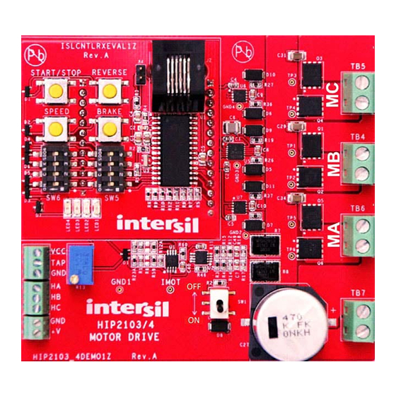
FIGURE 1. HIP2103-4DEMO1Z INPUTS AND OUTPUTS
The controller section is a daughter card which contains push
buttons for reset, brake, reverse, and start/stop functions. Also
on the controller card are dip switches for configuration, LEDs
for status, and a programming port. As an option, a customer
designed controller daughter card can be substituted for the
Intersil supplied controller.
The speed control section includes an on-board potentiometer
for speed control or an optional external potentiometer can be
connected to the signal terminal block.
The current sense section includes current amplifiers,
comparators, and current sense resistors.
AN1899
Rev 0.00
January 8, 2014
Page 1 of 24
Advertisement

Related Manuals for Renesas HIP2103-4DEMO1Z


Summary of Contents for Renesas HIP2103-4DEMO1Z
- Page 1 Introduction implementation of the HIP2103 and HIP2104 drivers including recommended support circuits. The HIP2103-4DEMO1Z is a general purpose motor drive with Also covered is the design method of the bipolar current a microprocessor controller. Three motor drive topologies are sensing feature. Presently, current sensing on this demo board...
-
Page 2: Block Diagram
4 push-buttons. Block Diagram The Hall sensor inputs are decoded by the microcontroller to The HIP2103-4DEMO1Z is composed of seven major circuit provide the appropriate switching sequence signals to the 3 function illustrating the use of several Intersil products. The HIP2103/4s to drive the six bridge FETs that drive a 3-phase following descriptions reference Figure 2. -
Page 3: Related Literature
Current Sensing/Current Limit • Temperature probe (optional) Two Intersil low offset, dual op-amps (ISL28246) are used for Caution: Although the HIP2103-4DEMO1Z has large heat current monitoring and current limiting. One op-amp is dissipating copper planes on the power FETS, if it is... - Page 4 DC Motor Setup (Full Bridge) 13. Continue to rotate the pot until the motor is running at a The HIP2103-4DEMO1Z can also be used to drive a conventional moderate speed of roughly 25%. Do not run the motor with brushed DC motor. The setup procedure is essentially the same maximum voltage until the setup check-out is completed.
- Page 5 HALF BRIDGE off Factory test on Other settings (error) Theory of Operation (3-Phase) The HIP2103-4DEMO1Z demonstration board is a general purpose 3-phase BLDC motor controller. Three half bridge power circuits drive the motor as shown in Figure 3. Sequence Step numbers FIGURE 4.
- Page 6 HIP2103-4DEMO1Z Switching Sequence Phase Currents The HIP2103-4DEMO1Z demo board has 6 gate drive outputs, two per HIP2103/4 (HO and LO), to control the six bridge FETs The following motor winding diagrams illustrate how currents individually. If the gate drives for both FETs of one half bridge are...
- Page 7 BOM and schematic found at the end of this application note. Current Monitor and Current Limit Vbat There are two current control features in the HIP2103-4DEMO1Z. A linear current monitor op amp, U2, amplifies the voltage across R21 and R22. This op amp is configured as a true differential amplifier to allow Kelvin connections across the current sensing resistors (see Figure 9).
- Page 8 R21||R22 = 0.030Ω for the diff- amp topology). An alternative method for changing the pulse-by-pulse current is Using the defaults values of the HIP2103-4DEMO1Z, Equation 1 to change the gain of the diff-amp. simplifies to: For example, if it is desired to decrease the current limit to 10A Vout = [16.2K /1.661K] x (.0075) x I...
- Page 9 Also, because the 0 degree applying power to the HIP2103-4DEMO1Z. Known specific motor part numbers are labeled in green boxes. Dip switch positions hall sensor logic options are defined by the blue boxes:...
- Page 10 HIP2103-4DEMO1Z Selecting the Correct Switching Sequence Notice that the dip switch settings for these Hall sensor logic charts are the same as on the previous page. This is not an error. Dip switch positions hall sensor logic options are defined by the blue boxes:...
- Page 11 BIll of Materials, Mother Board PART NUMBER REF DES MANUFACTURER DESCRIPTION 1725656 PHOENIX-CONTACT 100 Mil Micro-Pitch Terminal Block 1725669 TB1, TB2 PHOENIX-CONTACT 100 Mil Micro-Pitch Terminal Block 1729018 TB4-TB7 PHOENIX-CONTACT 200 Mil PCB Connector Terminal Block 3299W-1-103-LF BOURNS TRIMMER POTENTIOMETER (RoHS COMPLIANT) 90147-1112 MOLEX 12 PIN SINGLE ROW VERTICAL PCB FEMALE CONNECTOR...
- Page 12 BIll of Materials, Mother Board (Continued) PART NUMBER REF DES MANUFACTURER DESCRIPTION ISL28246FUZ U1,U2 LINEAR DUAL RAIL TO RAIL OUTPUT AMPLIFIER (Pb-Free) SiR662DP-T1-GE3 Q1-Q6 VISHAY N-Channel 60V 60A WFET TP_20C40P-DNP TP1-TP6, GND1-GND4, IMOT GENERIC Test Point .040 Pad 0.020 Thole (Do Not Populate) WSH2818R0150FE R7, R8 VISHAY...
- Page 13 Schematic, Daughter Card (controller) PROGRAMING IMOT PORT reset 555165-1 V_5/3.3 MCLR V_5/3.3 MCLR V_12 PWM4 PWM5 PWM3 PWM2 PWM1 AVDD PWM0 AVSS CSTCE10M0G55 OSC1 4.7UF OSC2 /FLTA 10MHZ PIC18F2431S0 MICROCONTRO DRAWN BY: DATE: ENGINEER RICHARD GARCIA 07/08/2013 RICH RELEASED BY: DATE: TITLE: UPDATED BY:...
- Page 14 Schematic, Mother Board (Controller Socket) CONTROLLER SOCKET REMOVE RJ1 FOR EXTERNAL POTENTIOMETER (OPTIONAL) V_5/3.3 IMOT V_12 PWM4 PWM5 PWM3 PWM2 PWM1 /FLTA PWM0 HALL SWITCHES HALL BIAS...
- Page 15 Schematic, Mother board (Bridge and Current Sense) V_48V VDEN GND_SIGNAL VDEN VBAT VCEN 0.1UF V_5/3.3 V_12 PWM3 PWM2 GND4 EP(VSS) HIP2104FRTAANZ HIP2104FRAANZ 0.1UF PWM5 PWM4 EP(VSS) GND3 HIP2103FRAAZ HIP2103FRTAAZ 0.1UF PWM1 PWM0 EP(VSS) GND2 HIP2103FRAAZ HIP2103FRTAAZ CSENSE IMOT V_5/3.3 R12A IMOT GND1 32.4K...
- Page 16 HIP2103-4DEMO1Z Silkscreen, Mother Board FIGURE 14. LAYER 1 AN1899 Rev 0.00 Page 16 of 24 January 8, 2014...
- Page 17 HIP2103-4DEMO1Z PCB, Mother Board FIGURE 15. TOP LAYER AN1899 Rev 0.00 Page 17 of 24 January 8, 2014...
- Page 18 HIP2103-4DEMO1Z PCB, Mother Board (Continued) FIGURE 16. LAYER 2 AN1899 Rev 0.00 Page 18 of 24 January 8, 2014...
- Page 19 HIP2103-4DEMO1Z PCB, Mother Board (Continued) FIGURE 17. LAYER 3 AN1899 Rev 0.00 Page 19 of 24 January 8, 2014...
- Page 20 HIP2103-4DEMO1Z PCB, Mother Board (Continued) FIGURE 18. BOTTOM LAYER AN1899 Rev 0.00 Page 20 of 24 January 8, 2014...
- Page 21 HIP2103-4DEMO1Z Silkscreen, Control Card PIC18F2431_CNTRL1Z Rev.A REVERSE START/STOP SPEED BRAKE FIGURE 19. SILKSCREEN AN1899 Rev 0.00 Page 21 of 24 January 8, 2014...
- Page 22 HIP2103-4DEMO1Z PCB, Control Card FIGURE 20. TOP LAYER AN1899 Rev 0.00 Page 22 of 24 January 8, 2014...
- Page 23 HIP2103-4DEMO1Z PCB, Control Card (Continued) FIGURE 21. BOTTOM LAYER AN1899 Rev 0.00 Page 23 of 24 January 8, 2014...
-
Page 24: Sales Offices
10. It is the responsibility of the buyer or distributor of Renesas Electronics products, or any other party who distributes, disposes of, or otherwise sells or transfers the product to a third party, to notify such third party in advance of the contents and conditions set forth in this document. - Page 25 Mouser Electronics Authorized Distributor Click to View Pricing, Inventory, Delivery & Lifecycle Information: Renesas Electronics HIP2103-4DEMO1Z HIP2103-4DEMO2Z...
Need help?
Do you have a question about the HIP2103-4DEMO1Z and is the answer not in the manual?
Questions and answers