Table of Contents
Advertisement
Quick Links
Advertisement
Table of Contents

Subscribe to Our Youtube Channel
Related Manuals for DFI FS051


Summary of Contents for DFI FS051
- Page 1 FS051 Embedded SBC 2.5” User’s Manual A40010835...
-
Page 2: Copyright
Copyright FCC and DOC Statement on Class B This publication contains information that is protected by copyright. No part of it may be re- This equipment has been tested and found to comply with the limits for a Class B digital produced in any form or by any means or used to make any transformation/adaptation without device, pursuant to Part 15 of the FCC rules. -
Page 3: Table Of Contents
Table of Contents I/O Connectors ..............15 Digital I/O Connector ............. 15 COM (Serial) Ports ............16 Front Panel Connector ............ 17 SATA (Serial ATA) Connector (for i.MX6 Quad only) ... 17 Copyright ........... 2 LVDS LCD Panel Connector ..........18 Panel Backlight/SATA Power Connector ...... -
Page 4: Warranty
Warranty Static Electricity Precautions 1. Warranty does not cover damages or failures that arised from misuse of the product, in- It is quite easy to inadvertently damage your PC, system board, components or devices even ability to use the product, unauthorized replacement or alteration of components and prod- before installing them in your system unit. -
Page 5: About The Package
About the Package The package contains the following items. If any of these items are missing or damaged, please contact your dealer or sales representative for assistance. • One FS051 board • One terminal block for RS485 • One heat spreader (Height: 11mm) Optional Items •... -
Page 6: Chapter 1 - Introduction
Chapter 1 Chapter 1 - Introduction Specifi cations SYSTEM Processor NXP i.MX6 Cortex-A9 DualLite, 1.0 GHz POWER Type Single 5V +/-10% DC NXP i.MX6 Cortex-A9 Quad, 1.0 GHz Connector Terminal block (2 poles) DC Jack (available upon request) Memory 1GB/2GB SDRAM Memory Down Single Channel DDR3L 1600MHz Consumption Typical: i.MX6:5V @ 0.460A (2.30Watt) -
Page 7: Features
Chapter 1 Features • DDR3L DDR3L SDRAM provides backward compatibility to DDR3 memory modules but can operate at the same or at a lower power level. • Storage The board features SD card and eMMC memory for storing system firmware. with the i.MX6 Quad processor, an additional Serial ATA 2.0 port is provided for storing system and user data. -
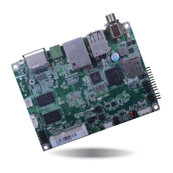
Page 8: Chapter 2 - Hardware Installation
Chapter 2 Chapter 2 - Hardware Installation Board Layout USB 2.0 Front COM 2 USB 3-4 Panel DC-in COM 3 LCD/Inverter/SATA Power LVDS LCD Panel Auto Power/Panel Power Select (JP1) eMMC USB 2.0 USB 0-1 JTAG (optional) CANbus Debug LED LAN 1 USB OTG COM 1... -
Page 9: Block Diagram
Chapter 2 Block Diagram Mechanical Diagram DDR3L 1600MHz Memory Down 97.05 HDMI HDMI 91.05 SATA 2.0 SATA 1x LVDS LVDS NOR Flash RGMII GLAN AR8033 CANBus CANBus 62.39 USB HOST Front Panel i.MX6 USB 2x USB2517 USB HUB UART TEST 47.62 USB 2.0 USB 2x... -
Page 10: System Memory
Chapter 2 Jumper Settings Important: Electrostatic discharge (ESD) can damage your board, processor, disk drives, add-in Auto Power-on Select & Panel Power Select boards, and other components. Perform installation procedures at an ESD workstation only. If such a station is not available, you can provide some ESD protection by wear- 2 4 6 ing an antistatic wrist strap and attaching it to a metal part of the system chassis. -
Page 11: Boot Mode/Device Select
Chapter 2 Boot Mode/Device Select 1 2 3 4 5 6 7 8 1 2 3 4 5 6 7 8 To select the boot mode and boot device, please use finger switch SW5. Boot Mode Select Boot from the fuses 7 Off, 8 Off Serial downloader 7 On, 8 Off... -
Page 12: I/O Ports
Chapter 2 I/O Ports 5V DC-in Terminal Block DC-in Power USB 2.0 HDMI Button Jack (optional) USB OTG The I/O ports consist of the following: • One 5V DC-in 2-pin terminal block or jack (optional) • Two USB 2.0 ports •... -
Page 13: Graphics Interface
Chapter 2 Graphics Interface RJ45 LAN Port The display port consists of the following: • 1 HDMI port LAN 1 HDMI Features • 1 RJ45 LAN port provided by Atheros AR8033 Ethernet controller (10/100/1000Mbps) The LAN port enables the system board to connect to a local area network with a network hub. -
Page 14: Usb Ports
Chapter 2 USB Ports Serial Port USB 3-4 USB 1 USB 2.0 USB 0 USB 2.0 The USB device allows data exchange between your computer and a wide range of simultane- ously accessible external Plug and Play peripherals. The system board is equipped with 2 onboard USB 2.0 ports (USB 0-1). The 10-pin connector allows you to connect 2 additional USB 2.0 ports (USB 3-4). -
Page 15: Usb Otg Port
Chapter 2 USB OTG Port I/O Connectors Digital I/O Connector USB OTG 1 2 3 4 5 6 7 8 Digital I/O The Digital I/O connector supports 8-bit digital input/output signals to provide powering-on function of the connected devices. Pin Name The USB OTG (USB 2.0) port is used for USB communication. -
Page 16: Com (Serial) Ports
Chapter 2 COM (Serial) Ports COM 2 Connector COM 3 Connector Pins RS-232 Pins RS-232 Full RS-422 RS-485 COM 3 COM 2 MDCD2- TX_B R(B)/T(B) COM 2: RS232 MDSR2- COM 3: RS232/422/485 MSIN2- TX_A R(A)/T(A) MRTS2- MSO2- RX_A MCTS2- MDTR2- RX_B MRI2- 1 2 3 4 5 6 7 8... -
Page 17: Front Panel Connector
Chapter 2 Front Panel Connector SATA (Serial ATA) Connector (for i.MX6 Quad only) Front Panel 1 2 3 4 5 6 7 8 SATA Power Button This switch is used to power on or off the system. Features Reset Button •... -
Page 18: Lvds Lcd Panel Connector
Description: Wafer connector, 14 pin, 1.25mm (pitch), White, 3.45mm (height), SMT type, 90 degree Panel Backlight/SATA Power LVDS LCD Panel 2. DFI board's Panel Backlight/SATA power connector: Manufacturer: E-call Part No: 0110-3221050 Description: Wafer connector, 5 pin, 1.25mm (pitch), 3.45mm (height), SMT type, 90 degree, White 3. -
Page 19: Expansion Slots
Chapter 2 Expansion Slots C Connector 1 2 3 4 5 6 7 8 SIM Slot (optional) microSD Mini PCIe The I C connector is used to monitor or communicate with system components. Pin Name Mini PCI Express Slot 3.3V The full-size Mini PCIe socket supports PCIe x1 signals and is used to install a Mini PCIe card. -
Page 20: Debug Connectors
Chapter 2 Debug Connectors CANbus Connector JTAG CANbus Debug The JTAG and debug connectors are used for debugging purposes. The CAN bus (Controller Area Network) connector is used for interconnecting electronic control units (ECUs). Debug Connector JTAG Connector Pin Name Pin Name Pin Name Pin Name... -
Page 21: Battery Connector
Chapter 2 Battery Connector Battery Connector Connect to the battery connector Battery The lithium ion battery powers the real-time clock. It is an auxiliary source of power when the main power is shut off. Safety Measures • Danger of explosion if battery incorrectly replaced. •... -
Page 22: Chapter 3 - Software User Guide
Introduction Set the finger switch SW5 to “Serial Downloader Mode”: pins 7 on and 8 off. FS051 platform is an embedded system with Yocto 1.8 preloaded on eMMC. Demo images are supported under Yocto 1.8 and Android 5.1.1 environment. 1 2 3 4 5 6 7 8 Check Board Type 2. - Page 23 3. Unzip Image package on your PC. 7. After the burning is done, click “Stop” and turn the power off. 4. Yocto image: execute “\\[core type]\yocto-emmc-fs051-[core type]-all.vbs”. For example, for DualLite CPU, execute “\\DualLite_core\yocto-emmc-fs051-DualLite-all.vbs”. Android image: execute “\\[core type]\android-emmc-fs051-[core type]-all.vbs”. For example, for DualLite CPU, execute “\\DualLite_core\android-emmc-fs051-DualLite-all.vbs”.
-
Page 24: Download Uboot Images To Spi With Mfgtool
1 2 3 4 5 6 7 8 7. After all preparation is done, click “Start” to burn the file. Wait until the process ends. 3. Plug in the Micro USB cable to your PC and power-on the FS051. Important: The adapter output voltage is 5V for FS051. -
Page 25: Download Images To Sd Card With Mfgtool
Set the finger switch SW5 to “SD Card Download Mode”: pins 1, 3, 6, 7 on and 2, 4, 5, 8 off. 1 2 3 4 5 6 7 8 2. Plug in the Micro USB cable to your PC and power-on the FS051. Important: 1. The adapter output voltage is 5V for FS051. - Page 26 7. After all preparation is done, click “Start” to burn the file. Wait until the process ends. 4. Yocto image: execute “\\[core type]\SDBoot\yocto-sdcard-fs051-[core type]-all.vbs”. For example, for Quad CPU, execute “\\Quad_core\SDBoot\yocto-sdcard-fs051-Quad-all.vbs”. Android image: execute “\\[core type]\SDBoot\android-sdcard-fs051-[core type]-all.vbs”. For example, for Quad CPU, execute “\\Quad_core\SDBoot\android-sdcard-fs051-Quad-all.vbs”.
-
Page 27: Software Features
Chapter 3 9. Set the finger switch SW5 to the “SD Card Start Mode”: pins 1, 3, 6, 8 on and 2, 4, 5, 7 Software Features off. General Support (*) is depended on the NXP support. 1 2 3 4 5 6 7 8 Component Name Base-Line Feature Yocto 1.8 - Kernel 3.14.52 (default preloaded on eMMC) -
Page 28: Yocto Support
Chapter 3 Yocto Support Component Support Status (*) is depended on the NXP support. Support Loopback & fl ow control test, BR 115200 (need DFI Linux user UART1 - RS232 space utility) Component Support Status Support Loopback test, BR 115200 (need DFI Linux user space utility) -
Page 29: Android Support
USB 2.0 second USB is not available. If fi rst USB is unplugged, second USB needs Support Loopback & fl ow control test, BR 115200 by DFI Android UART UART1 - RS232 to be unplugged and re-plugged back to be available.) FAT32 fi lesystem... - Page 30 Fastboot Not support Android OTA Not support Android CTS Android GMS/ Not support Not support suspend, set never to suspend by default. The power Android Suspend key supports suspend function on FS051 device. Chapter 3 Software User Guide www.dfi .com...
Need help?
Do you have a question about the FS051 and is the answer not in the manual?
Questions and answers