
Related Manuals for Flowserve Durametallic X-200


Summary of Contents for Flowserve Durametallic X-200
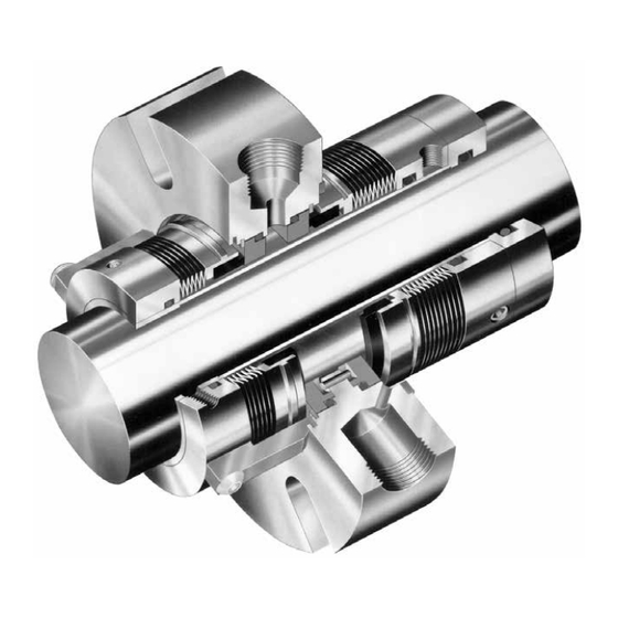
- Page 1 Installation Instructions Durametallic X-200 ® Cartridge dual metal bellows seal for standard and big bore ANSI pumps Experience In Motion...
-
Page 2: Equipment Check
Congratulations You have just purchased a reliable, long-life product manufactured by the leading manufacturer of sealing systems in the world. With proper installation and operation, this X-200 seal can be a valuable contributor to your operation by significantly reducing the mean time between planned maintenance (MTBPM) of your rotary equipment. - Page 3 X-200 Dimensional Data Figure 2 4 - G Ø studs equally spaced on H B.C. Note: Washers may be required for stud sizes smaller than G .03" M (N.P.T.) outlet Seal flush Size outlet Dimensional Data for X-200 Seal, inch Seal Size +0.000 -0.002...
- Page 4 Disassemble equipment in accordance with equipment manufacturer’s instructions to allow access to seal installation area. Remove existing mechanical seal and gland or compression packing and packing gland (follower flange). Make sure the shaft or sleeve is free of burrs, cuts, dents, or corrosion that might cause leakage past the sleeve gasket, as shown on the assembly drawing.
- Page 5 Lubricate the shaft or sleeve OD lightly with silicone lubricant provided and slide the complete X-200 cartridge seal onto the shaft, Figure 3, with the end with the setting devices toward the bearing housing. Install pump backplate Figure 4 Install the pump back plate (stuffing box), Figure 4. Position the X-200 seal gland flush connection, port a in Figure 7, in the 3:00 o’clock position for normal installations with CW rotation (9:00 o'clock for CCW rotation) for optimum heat removal.
- Page 6 Tighten the set screws on the X-200 cartridge collar with the Allen wrench provided, Figure 5. Remove setting devices by removing the cap screws with the Allen wrench provided, Figure 6. Save the setting devices for use if pump impeller must be reset or if the X-200 is removed for mainte- nance.
- Page 7 Pipe a product bypass flush from the pump discharge to the X-200 seal flush port, Figure 7. To maximize seal life, Flowserve recommends that a product bypass flush be used whenever possible with a X-200 seal installed in conventional stuffing box. A bypass flush is not necessary when an enlarged tapered or cylindrical seal chamber is used.
- Page 8 X-200 inner and outer seals below that of the product pressure acting on the outside of the inner seal. Flowserve can supply information on buffer fluid flow requirements based on seal size, product temperature, barrier fluid characteristics, and shaft speed.
- Page 9 Dual pressurized X-200 with Supply Tank Figure 8 Pressure source normally open Pressure indicator Pressure switch Bypass line (low) from pump discharge Supply tank Orifice Level switch (low) assembly option 1.2 m (4 feet) maximum Cooling coils 0.45 -0.6 m Drain (1.5 - 2 feet) normally...
-
Page 10: Operation
Do not exceed the temperature limits of the X-200. The materi- als of construction are listed on the assembly drawing. For the tem- perature limits of materials consult Flowserve. Turn on any cooling water to the supply tank before start-up. - Page 11 This product is a precision sealing device. The design and dimension tolerances are critical to seal performance. Only parts supplied by Flowserve should be used to repair a seal. To order replacement parts, refer to the part code and B/M number. A spare backup seal should be stocked to reduce repair time.
- Page 12 Flowserve Corporation has established industry leadership in the design and manufacture of its products. Telephone: 31 765 028 200 When properly selected, this Flowserve product is designed to perform its intended function safely during its useful life. However, the purchaser or user of Flowserve products should be aware that Flowserve products Telefax: 31 765 028 487 might be used in numerous applications under a wide variety of industrial service conditions.
Need help?
Do you have a question about the Durametallic X-200 and is the answer not in the manual?
Questions and answers