
Related Manuals for Flowserve Durametallic P-50


Summary of Contents for Flowserve Durametallic P-50
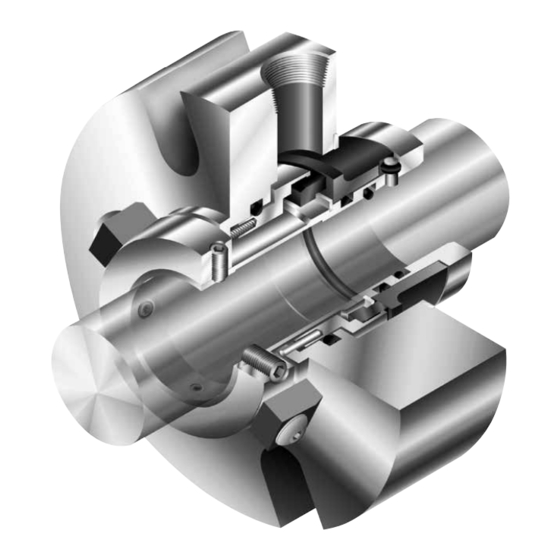
- Page 1 Installation Instructions Durametallic P-50 ® A cartridge mounted, flexible stator pusher seal design for general service applications Experience In Motion...
-
Page 2: Equipment Check
Congratulations You have just purchased a reliable, long-life product manufactured by the leading manufacturer of sealing systems in the world. With proper installation and operation, this P-50 seal can be a valuable contributor to your operation by significantly reducing the mean time between planned maintenance (MTBPM) of your rotary equipment. - Page 3 Check equipment dimensions to ensure that they are within the dimensions shown in Figures 1 and 2. Critical dimensions include shaft or sleeve OD (A), a chamber depth of at least 25.4 mm (1.000 inch), minimum and maximum seal housing bore (B), and the minimum distance to the first obstruction (F).
- Page 4 P-50 Figure 2 F minimum distance to first obstruction 1.00 inch Minimum Box Depth inch Shaft & Seal Size Dimensional Data (inches) Min. Bolt Circle for Bolt Dia. Shaft & .375 .500 .625 .750 Seal Size (Min) (Max) 1.000 1.625 2.000 1.50 1.750 1.88...
-
Page 5: Installation
Note: No seal setting measurements are needed to install the P-50 seal. Instructions are for vertically split case end-suction ANSI pumps. Modifications of the procedure may be required for other style pumps. Consult Flowserve. Tools needed for installation: • An open end wrench for the gland bolt nuts •... - Page 6 Position the P-50 with the gland tight against the seal chamber face. Turn the gland so that the flush tap is as close to the 12:00 o'clock position as possible and so that the flush piping will clear the bearing frame. Tighten the gland nuts evenly in a diagonal sequence.
-
Page 7: Operational Recommendations
This product is a precision sealing device. The design and dimension tolerances are critical to seal performance. Only parts supplied by Flowserve should be used to repair a seal. To order replacement parts, refer to the part code and B/M number. A spare backup seal should be stocked to reduce repair time. -
Page 8: Repair Procedures
O-ring Gasket Retaining Ring Figure 7 For special problems encountered during the repair procedure, contact your nearest Flowserve Sales and Service Representative. 4.2 Disassembly 4.2.1 Replace the centering tabs on the sleeve collar before removal of the gland bolt nuts. - Page 9 Parts which may be reused if in satisfactory condition include the sleeve, gland and sleeve collar. Parts which may be reconditioned by an authorized Flowserve repair facility include the rotor and stator. 4.3 Re-assembly 4.3.1 Install new set screws into the...
- Page 10 O-ring, the O-ring will not be used. Figure 11 Note: If Duraflon encapsulated O-rings are to be installed, contact your local Flowserve repair facility for proper installation. 4.3.3 Install the rotor onto the sleeve aligning the drive slot with the pin.
- Page 11 Coat the stator O-ring with 4.3.7 silicone lubricant and install it into the gland ring groove. Place the gland ring over 4.3.8 the stator being careful to engage the anti-rotation pins. See Figure 15. Install the sleeve collar onto 4.3.9 the sleeve and align the set screws with the holes.
- Page 12 Flowserve Corporation has established industry leadership in the design and manufacture of its products. Telephone: 31 765 028 200 When properly selected, this Flowserve product is designed to perform its intended function safely during its useful life. However, the purchaser or user of Flowserve products should be aware that Flowserve products Telefax: 31 765 028 487 might be used in numerous applications under a wide variety of industrial service conditions.
Need help?
Do you have a question about the Durametallic P-50 and is the answer not in the manual?
Questions and answers