
Related Manuals for Flowserve Interseal SLC Series


Summary of Contents for Flowserve Interseal SLC Series
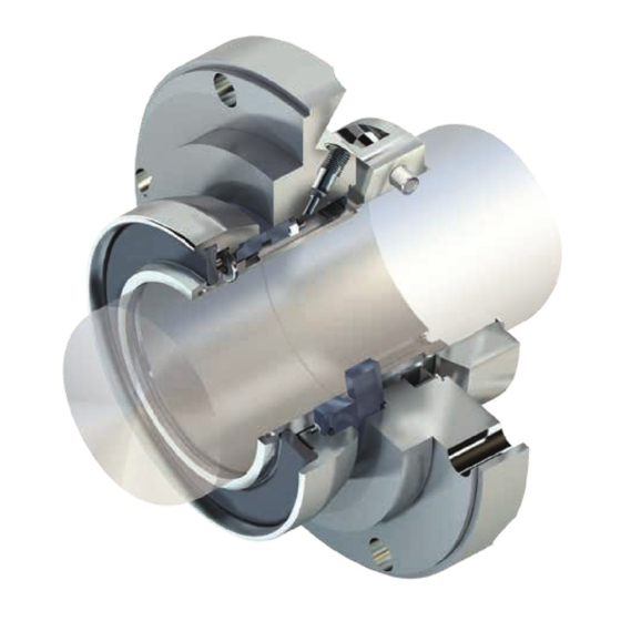
- Page 1 Installation Instructions Interseal SLC Series Self contained single cartridge heavy duty slurry seal Experience In Motion...
- Page 2 Incorrect installation, operation or maintenance can result in personal injury or death to personnel and damage to the equipment. For special problems encountered during installation, contact your nearest Flowserve Sales and Service Representative or Authorized Distributor.
- Page 3 Equipment Preparation for Mechanical Seal Installation Follow plant safety regulations prior to equipment disassembly: • lock out motor/driver and valves. • wear designated personal safety equipment. • relieve any pressure in the system. • consult plant MSDS files for hazardous material regulations. •...
- Page 4 Shaft radial run out should be less than 0.13 mm (0.005 inch) FIM (TIR). See Figure 3. Turn shaft 360° and observe the movement. Excessive movement may indicate a bent or warped shaft that needs replacement. Check Radial Shaft Deflection Figure 3 0.13 mm (0.005 inch) FIM (TIR) Maximum Acceptable Radial Run Out...
- Page 5 For adapters provided with a centering jig, simply insert the centering jig into the adapter and tighten adapter bolts, alternately adjusting the cover location until the centering jig can be removed by hand. Adapter Plate Mounting Surface Perpendicular to Shaft Figure 5 Adapter Mounting Surface to be Perpendicular to Shaft within...
- Page 6 Slide retaining bolts through the rear face of the adapter plate and screw into seal flange/gland. Evenly tighten retaining bolts to pull the seal into the adapter fit. See Figure 7. Draw Cartridge into Adapter Using Attachment Bolts Figure 7 With the Spacer Ring Removed Evenly Tighten Flange/Gland Bolts to Start the Seal into the Adapter...
- Page 7 4.11 For installations with a 2 piece seal split clamp/drive collar; align the seal clamp/ drive collar split lines and alignment key with the seal sleeve slots. This will ensure maximum clamping force. See Figure 14. 4.12 Evenly tighten the split clamp/drive collar SHCS (group 1-3 standard), the 3 piece tapered ring SHCS (group 4-5 standard), or the cup point drive set screws (special use with non-hardened shaft or shaft sleeve) to the proper torque val- ues.
- Page 8 Apply a light coating of O-ring lubricant to the index finger and thumb and pull seal sleeve and flange/gland O-ring element through fingers to inspect for nicks or cuts. Install O-rings in their proper groove locations. This process will help prevent an excessive amount of lubricant from being applied to the O-ring ele- ments (non-petroleum based grease must be used with EPDM materials).
- Page 9 For adapters provided with a centering jig, simply insert the centering jig into the adapter and tighten adapter bolts, alternately adjusting the cover location until the centering jig can be removed by hand. Dial indicate front face of seal fit on the adapter plate. This fit must be perpen- dicular to the shaft within 0.25 mm (0.010 inch) FIM (TIR).
- Page 10 Install bearing assembly into equipment case. Make any necessary impeller adjustments. Important: Loosen bearing assembly and drive belts only enough to make adjustment. Fully tighten bearing assembly bolts after adjustment. 5.10 For installations with a 2 piece seal split clamp/drive collar; align the seal clamp/ drive collar split lines and alignment key with the seal sleeve slots.
- Page 11 Close the suction valve. • Open the discharge washout/bleed valve. Close the valve after a steady stream of clear liquid flows from it. For special problems encountered during installation, contact your nearest Flowserve Sales and Service Representative or Authorized Distributor.
- Page 12 Flowserve Corporation has established industry leadership in the design and manufacture of its products. Telephone: 31 765 028 200 When properly selected, this Flowserve product is designed to perform its intended function safely during its useful life. However, the purchaser or user of Flowserve products should be aware that Flowserve products Telefax: 31 765 028 487 might be used in numerous applications under a wide variety of industrial service conditions.
Need help?
Do you have a question about the Interseal SLC Series and is the answer not in the manual?
Questions and answers