
Subscribe to Our Youtube Channel
Related Manuals for Flowserve Durametallic P-200


Summary of Contents for Flowserve Durametallic P-200
- Page 1 Installation Instructions Durametallic P-200 ® Cartridge dual pusher seal for standard and big bore ANSI pumps Experience In Motion...
-
Page 2: Equipment Check
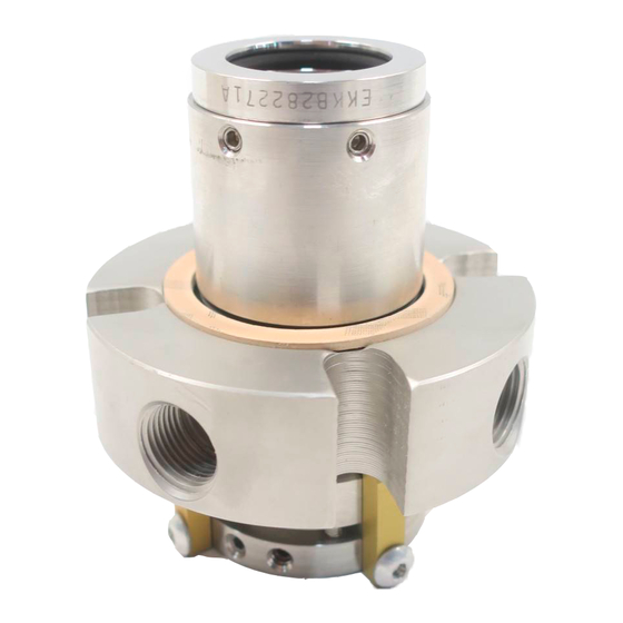
Description This P-200 seal is a dual, cartridge mounted, end face mechanical seal, designed for ease of installation. No seal setting dimensions are required. Removable setting devices provide proper alignment. Installa- tion according to the following steps will ensure a long trouble-free life of the P-200 seal. - Page 3 P-200 Dimensional Data Figure 2 NPT for sealing fluid inlet and outlet. ø Shaft & Seal Size ø studs NPT marked "Flush" should be equally plugged when not used for flushing spaced on J Dimensional Data for P-200 Seal (inches) Shaft & Box Bore Box Depth Seal Seal Gland NPT Bolt Dia. Bolt Circle Gland OD Seal Size...
- Page 4 Disassemble equipment in accordance with equipment manufac- turer’s instructions to allow access to seal installation area. Remove existing mechanical seal and gland or compression packing and packing gland (follower flange). Make sure the shaft or sleeve is free of burrs, cuts, dents or corrosion that might cause leakage past the sleeve gasket, as shown on the assembly drawing.
- Page 5 P-200 Seal Installation Tools needed: • Open-end wrench for gland nuts • Allen wrenches provided • Silicone lubricant provided Lubricate the shaft or sleeve OD lightly with the silicone lubricant provided and slide the complete P-200 cartridge seal onto the shaft, with the end with the setting devices toward the bearing housing.
- Page 6 See Operational Recommendations, Section 4, before starting pump. Piping Install an ANSI 7311 flush for horizontal pumps or ANSI 7313 for vertical pumps. from the pump discharge to the P-200 seal flush port, a Figure 4. To maximize seal life, Flowserve recom- mends a product bypass flush be used whenever possible with a P-200 seal installed in conventional stuffing box. A bypass flush is not necessary when an enlarged tapered or cylindrical seal cham- ber is used. If a bypass flush is not used, plug the flush port a...
- Page 7 Taps in the gland are buffer/ barrier fluid inlet and outlet ports. Which is the inlet port depends on the direction of shaft rotation. Shaft Rotation from Exposed End of Gland Figure 4 Counterclockwise Rotation (CCW) Clockwise Rotation (CW) (most ANSI pumps) Inlet Port Inlet...
- Page 8 Flowserve can supply information on buffer fluid flow requirements based on seal size, product temperature, buffer fluid characteris- tics, and shaft speed. The Flowserve supply tank is designed to work with the P-200 seal to form a self-contained sealing system. The circulating feature in the P-200 provides a positive buffer/barrier fluid flow from the seal cavity to the supply tank and back to the seal.
- Page 9 Dual pressurized P-200 with Supply Tank Figure 5 Pressure source normally open Pressure indicator Pressure switch Bypass line (low) from pump discharge Supply tank Orifice Level switch (low) assembly option 1.2 m (4 feet) maximum Cooling coils 0.45 -0.6 m Drain (1.5 - 2 feet) normally...
-
Page 10: Operation
Do not exceed the temperature limits of the P-200. The materials of construction are listed on the assembly drawing. For the temperature limits of materials, consult Flowserve. Turn on any cooling water to the supply tank before start-up. Do not start up or run the P-200 dry. Buffer/barrier fluid must be in the seal cavity at all times during pump operation. - Page 11 Repair This product is a precision sealing device. The design and dimension tolerances are critical to seal performance. Only parts supplied by Flowserve should be used to repair a seal. To order replacement parts, refer to the part code and B/M number. A spare backup seal should be stocked to reduce repair time. When seals are returned to Flowserve for repair, decontaminate the seal assembly and include an order marked "Repair or Replace."...
- Page 12 Etten-Leur, the Netherlands Flowserve Corporation has established industry leadership in the design and manufacture of its products. When properly selected, this Flowserve product is designed to perform its intended function safely during its Telephone: 31 765 028 200 useful life. However, the purchaser or user of Flowserve products should be aware that Flowserve products might be used in numerous applications under a wide variety of industrial service conditions.
Need help?
Do you have a question about the Durametallic P-200 and is the answer not in the manual?
Questions and answers