
Related Manuals for ESAB Renegade EC 1000


Summary of Contents for ESAB Renegade EC 1000
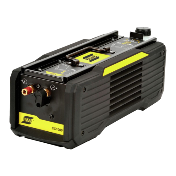
- Page 1 EC 1000 Service manual Valid for: serial no. 720-xxx-xxxx 0463 428 001 GB 20170519...
-
Page 2: Table Of Contents
Replacing the water pump............... Replacing the cooling fan................ Replacing the heat exchanger ..............Replacing the cooler board ..............Replacing the coolant ................SPARE PARTS AND ACCESSORIES ............. Rights reserved to alter specifications without notice. 0463 428 001 © ESAB AB 2017... -
Page 3: Read This First
The manual is valid for: EC 1000 with serial number 720-xxx-xxxx NOTE! The unit is tested by ESAB in a general set-up. The responsibility for safety and function, of the specific set-up, lies with the integrator. The EC 1000 is designed and tested in accordance with the standards stated in the instruction manual. -
Page 4: Before Starting Service
BEFORE STARTING SERVICE BEFORE STARTING SERVICE Service aid ESAB can offer a number of service tools that will simplify the service. Antistatic service kit Ordering no. 0740 511 001 The kit makes it easier to protect sensitive components from electrostatic discharge. -
Page 5: Introduction
The cooling unit consists of a cooler board, a heat exchanger, a cooling fan, a diaphragm water pump, a coolant tank and an ELP (ESAB Logic Pump). The cooler board is powered and controlled from the welding power source. The water pump is circulating the coolant through the heat exchanger and onwards in the system. -
Page 6: Component Positions
INTRODUCTION Component positions Water pump 5AP1 cooler board Coolant thermal sensor Water tank Heat exchanger with cooling fan ELP (ESAB Logic Pump) 0463 428 001 - 6 - © ESAB AB 2017... -
Page 7: Error Codes
If the hose for coolant to the TIG torch is properly connected and error code Err 8 is still displayed, troubleshoot the switch for the ELP (see “Switch for ELP”, page 14). 0463 428 001 - 7 - © ESAB AB 2017... -
Page 8: Wiring Diagram
Cooling unit module Wire numbers 500–599 5AP1 Cooler board 5EV1 Cooling fan, 24 V DC Water pump with motor, 24 V DC Switch for ELP (ESAB Logic Pump) 5ST1 Coolant thermal sensor 5XS... Socket connector (Sleeve) 0463 428 001 - 8 -... - Page 9 WIRING DIAGRAM 0463 428 001 - 9 - © ESAB AB 2017...
-
Page 10: Technical Data
24 V DC, 3.0 A Cooling power 0.9 kW Noise < 70 dB(A) (Constant sound pressure when idling) Coolant ESAB's ready mixed coolant, see the "ACCESSORIES" chapter in the instruction manual. Coolant quantity 1.5 l Maximum water flow 1.8 l/min Max pressure lift for torch Q 4.5 bar (65 psi) -
Page 11: Software Update And Configuration
SOFTWARE UPDATE AND CONFIGURATION SOFTWARE UPDATE AND CONFIGURATION For information about software update and configuration of the welding equipment, see the "SOFTWARE UPDATE AND CONFIGURATION" chapter in the power source service manual. 0463 428 001 - 11 - © ESAB AB 2017... -
Page 12: Troubleshooting
For information about how to extract and interpret the service log, see the TROUBLESHOOTING chapter in the power source service manual. The script file needed to extract the service log, can be downloaded from your local country or region ESAB partner login site. Troubleshooting the electrical hardware Equipment •... -
Page 13: Cooling Fan
If there is no voltage, replace the cooler board (see section “Replacing the cooler board”, page 23). If the voltage is within the specification given above but the pump is still not running, replace the pump (see section “Replacing the water pump”, page 21). 0463 428 001 - 13 - © ESAB AB 2017... -
Page 14: Switch For Elp
(blue) and measure the voltage between pins 1 and 2 of connector CN4 on the cooler board 5AP1. The voltage should be 0 V. If the voltage is still 25 V, despite the fact that a TIG torch is connected, replace the ELP switch. 0463 428 001 - 14 - © ESAB AB 2017... -
Page 15: Coolant Thermal Sensor
Resistance over thermal sensor (Ω) ± approx. 3% 16 312 12 691 9 948 7 856 6 246 5 000 4 028 3 265 2 662 2 183 1 799 1 491 1 242 1 039 873.8 0463 428 001 - 15 - © ESAB AB 2017... -
Page 16: Status Indications On The Cooler Board 5Ap1
LED 3 (3 Hz flash) Overtemperature condition. The cooling liquid temperature has exceeded +65 °C (+149 °F). The LED will go out when the cooling liquid temperature has decreased below +55 °C (+131 °F). 0463 428 001 - 16 - © ESAB AB 2017... -
Page 17: Led 1 And Led 2 - Software Run Level
(3 Hz flash) Application running ok, Processing run state Green Application error (recoverable) Application error (non-recoverable). Power off or reset is required. Application in test or debug mode Green Application shut down 0463 428 001 - 17 - © ESAB AB 2017... -
Page 18: Disassembly And Reassembly
Remove the screws holding the cooling unit side panels (four screws in the left side panel and four screws in the right side panel). Remove the side panels. Remove the top panel. 0463 428 001 - 18 - © ESAB AB 2017... - Page 19 Make sure the top panel is fitted in the correct direction! The yellow arrow on the top panel decal should point towards the front of the cooler, i.e. towards the short side where the coolant connectors are located. 0463 428 001 - 19 - © ESAB AB 2017...
-
Page 20: Replacement Instructions
Insert the new CAN interface cable through the grommet and connect the harness to the afforementioned connectors. Tighten the cable grommet using the correct tightening torque according to the illustration. 0463 428 001 - 20 - © ESAB AB 2017... -
Page 21: Replacing The Water Pump
Slide out the pump sideways to the right. Insert the new pump and reinstall in the reverse order. Tighten the screws and the hose clips, using the correct tightening torques according to the illustration. 0463 428 001 - 21 - © ESAB AB 2017... -
Page 22: Replacing The Cooling Fan
Lift out the heat exchanger from the cooling unit. Attach and connect the new heat exchanger in the reverse order. Tighten all joints, using the correct tightening torques according to the illustration. 0463 428 001 - 22 - © ESAB AB 2017... -
Page 23: Replacing The Cooler Board
Flushing can only be performed via the red connection. Drain the coolant tank manually, i.e. empty it via the coolant filling hole. Fill new coolant into the tank, using ESAB's ready mixed coolant (see the "ACCESSORIES" chapter in the instruction manual). Follow the instructions regarding coolant filling and torch installation in the "INSTALLATION"... -
Page 24: Spare Parts And Accessories
These documents can be downloaded from the Internet: www.esab.com Document type File name Product Note Spare parts list 0463 427 001 EC 1000 Instruction manual 0445 030 * EC 1000 Ordering number 0445 045 880 0463 428 001 - 24 - © ESAB AB 2017... - Page 25 SPARE PARTS AND ACCESSORIES 0463 428 001 - 25 - © ESAB AB 2017...
- Page 26 ESAB subsidiaries and representative offices Europe THE NETHERLANDS North and South America SOUTH KOREA ESAB Nederland B.V. ESAB SeAH Corporation Amersfoort Kyungnam AUSTRIA ARGENTINA Tel: +31 33 422 35 55 Tel: +82 55 269 8170 ESAB Ges.m.b.H CONARCO Vienna-Liesing Fax: +31 33 422 35 44...
Need help?
Do you have a question about the Renegade EC 1000 and is the answer not in the manual?
Questions and answers