
Related Manuals for ESAB EM 235ic


Summary of Contents for ESAB EM 235ic
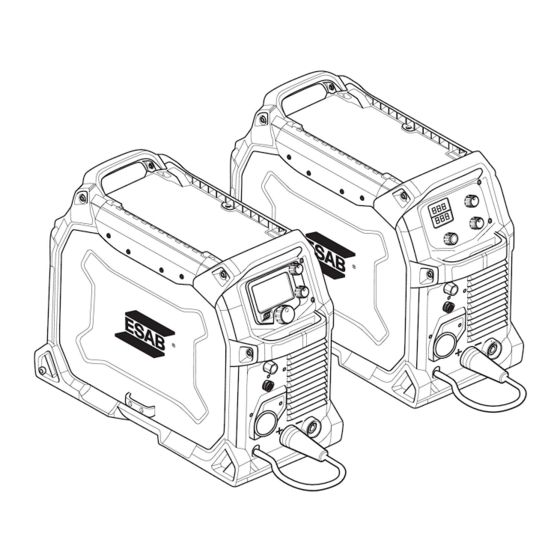
- Page 1 EMP 235ic, EM 235ic Instruction manual Valid for: serial no. EMP 235ic: 636-xxx-xxxx, EM 235ic: 640-xxx-xxxx 0463 479 001 US 20170627...
-
Page 2: Table Of Contents
6.1.7 Settings ....................6.1.8 User manual information ................ 6.1.9 Icon reference guide................How to navigate - EM 235ic ..............6.2.1 Symbol reference EM 235ic ..............MAINTENANCE ..................... 36 Routine maintenance ................Power source and wire feeder maintenance ......... 0463 479 001... - Page 3 ORDERING SPARE PARTS ................40 MIG WELD PARAMETER CHART ............... FRACTION TO DECIMAL CONVERSION ............DIAGRAM ......................ORDERING NUMBERS ..................WEAR PARTS....................... ACCESSORIES ....................REPLACEMENTS PARTS..................Rights reserved to alter specifications without notice. 0463 479 001 © ESAB AB 2017...
-
Page 4: Safety Precautions
Warn bystanders not to look at the arc and not to expose themselves to the rays of the electric-arc or hot metal. 0463 479 001 - 4 - © ESAB AB 2017... - Page 5 Connect the work cable to the workpiece. A poor or missing connection can expose you or others to a fatal shock. Use well-maintained equipment. Replace worn or damaged cables. Keep everything dry, including clothing, work area, cables, torch/electrode holder and power source. 0463 479 001 - 5 - © ESAB AB 2017...
- Page 6 Do not operate near degreasing and spraying operations. The heat or arc can react with chlorinated hydrocarbon vapors or liquids to form phosgene, a highly toxic gas, and other irritant gases. 0463 479 001 - 6 - © ESAB AB 2017...
- Page 7 Keep hands, hair, loose clothing and tools away from moving parts. Do not use gloves near moving parts. Reinstall panels or covers and close doors when service is finished and before starting engine. 0463 479 001 - 7 - © ESAB AB 2017...
- Page 8 NFPA Standard 51B, “Fire Prevention During Welding, Cutting, and Other Hot Work" CGA Standard P-1, “Precautions for Safe Handling of Compressed Gases in Cylinders” ANSI Z87.1, "Occupational and Educational Personal Eye and Face Protection Devices" 0463 479 001 - 8 - © ESAB AB 2017...
-
Page 9: User Responsibility
1 SAFETY PRECAUTIONS User responsibility Users of ESAB equipment have the ultimate responsibility for ensuring that anyone who works on or near the equipment observes all the relevant safety precautions. Safety precautions must meet or exceed the standard requirements that apply to this type of equipment. - Page 10 CAUTION! This product is solely intended for arc welding. ESAB has an assortment of welding accessories and personal protection equipment for purchase. For ordering information, contact your local ESAB dealer or visit us on our website. 0463 479 001 - 10 -...
-
Page 11: Introduction
2 INTRODUCTION INTRODUCTION The ESAB EM and EMP product family is a new generation of MIG and multi-process (MIG/Stick/TIG) welding power sources. All Rebel power sources are designed to match the needs of the user. They are tough, durable and portable, providing excellent arc performance across a variety of welding applications. - Page 12 Victor® Flow Meter with 10 ft (3 m) gas hose • ESAB OK AristoRod™ premium solid wire 0.035 in. (0.9 mm) 11# spool • ESAB Atom Arc Acclaim 1/8 in. premium stick electrodes 1# sample pack • Guide tubes 0.023 in. – 0.045 in. (0.6 mm – 1.2 mm) •...
-
Page 13: Technical Data
16 A / 20.6 V – 210 A / 28.4 V 16 A / 20.6 V – 130 A / 25.2 V Open circuit voltage (OCV) VRD deactivated 68 V 68 V VRD activated 35 V 35 V Efficiency Power factor 0.98 0.99 Wire feed speed 80-700 in./min 80-700 in./min (2.0-17.89 m/min) (2.0-17.89 m/min) 0463 479 001 - 13 - © ESAB AB 2017... - Page 14 Wire diameter Mild steel solid wire 0.023–0.045 in. (0.6–1.2 mm) 0.023–0.045 in. (0.6–1.2 mm) Stainless steel solid wire 0.030–0.045 in. (0.8–1.2 mm) 0.030–0.045 in. (0.8–1.2 mm) Flux cored wire 0.030-0.052 in. (0.8-1.3 mm) 0.030-0.052 in. (0.8-1.3 mm) Aluminum 0.030–0.045 in. (0.8–1.2 mm) 0.030–0.045 in. (0.8–1.2 mm) 0463 479 001 - 14 - © ESAB AB 2017...
- Page 15 Equipment marked IP 23S is intended for indoor and outdoor use; however, should not be operated in precipitation. Application class The symbol indicates that the power source is designed for use in areas with increased electrical hazard. 0463 479 001 - 15 - © ESAB AB 2017...
-
Page 16: Installation
Position the power source so that its cooling air inlets and outlets are not obstructed. A. 4 in. (100 mm) B. 4 in. (100 mm) Lifting instructions The power source can be lifted using any of the handles. 0463 479 001 - 16 - © ESAB AB 2017... -
Page 17: Mains Supply
An electrical shock or fire hazard is probable if the following electrical service guide recommendations are not followed. These recommendations are for a dedicated branch circuit sized for the rated output and duty cycle of the welding power source. 0463 479 001 - 17 - © ESAB AB 2017... -
Page 18: Connecting The Power Source To Input Supply
10 kW rated power, are recommended. 4.3.2 Connecting the power source to input supply Use one of the supplied adapters to connect the power source to mains. 0463 479 001 - 18 - © ESAB AB 2017... -
Page 19: Operation
WARNING! Make sure that the side covers are closed during operation. WARNING! Ensure spool retaining cotter pin is in place to prevent the spool from sliding off the hub. 0463 479 001 - 19 - © ESAB AB 2017... -
Page 20: Connections
For MIG/Stick process the output to which the welding cable is connected depends on the type of electrode, refer to electrode packaging for information relating to the correct electrode polarity. Connect the return cable to the remaining welding terminal on the power source. 0463 479 001 - 20 - © ESAB AB 2017... -
Page 21: Polarity Change
Wire feed mechanism Opening side cover Inserting and replacing wire EMP 235ic and EM 235ic will handle bobbin sizes of 4 in. (100 mm), 8 in. (200 mm) and 12 in. (300 mm). See TECHNICAL DATA chapter for suitable wire dimensions for each wire type. WARNING! Do not place or point the torch near the face, hand, or body as this may result in personal injury. - Page 22 Fit the appropriate velocity nozzle and contact tip. Close the side cover. Welding with aluminium wire In order to weld with aluminium wire use optional Spool gun. Refer to Instruction manual for Spool gun for set up. 0463 479 001 - 22 - © ESAB AB 2017...
-
Page 23: Setting The Wire Feed Pressure
Three dual groove feed rollers are supplied as standard. Change the feed roller to match the filler metal. NOTE! Be sure not to lose the key that is located on the drive motor shaft. This key must align with drive roll groove for proper operation. 0463 479 001 - 23 - © ESAB AB 2017... -
Page 24: Shielding Gas
). Aluminum and silicon bronze use pure argon gas (Ar). In the sMIG mode (see section "sMIG mode" in the CONTROL PANEL chapter) the optimal welding arc with the gas you use will be automatically set. 0463 479 001 - 24 - © ESAB AB 2017... -
Page 25: Volt-Ampere Curves
Other settings result in curves that fall between these curves. A=Welding current (AMPS), V=Output voltage SMAW (Stick) 230 V SMAW (Stick) 120 V GMAW (MIG) 230 V 0463 479 001 - 25 - © ESAB AB 2017... - Page 26 5 OPERATION GMAW (MIG) 120 V GTAW (TIG) 230 V GTAW (TIG) 120 V 0463 479 001 - 26 - © ESAB AB 2017...
-
Page 27: Duty Cycle
5 OPERATION Duty cycle The EMP 235ic and EM 235ic both have a welding current output of 235 A at 40% duty cycle (230 V). A self-resetting thermostat will protect the power source if the duty cycle is exceeded. Example: If the power source operates at a 40% duty cycle, it will provide the rated amperage for a maximum of 4 minutes out of every 10 minute period. -
Page 28: Overheating Protection
(EMP), or the overtemperature indicator is illuminated (EM). The overheating protection resets automatically when the temperature has returned to normal working temperature. 0463 479 001 - 28 - © ESAB AB 2017... -
Page 29: Control Panel
Stick/MMA mode Lift-TIG mode Settings User manual information Dialogue box 6.1.2 sMIG mode Home screen Information Memory MIG/Spool gun selection Parameter Wire feed speed Material thickness Trim box Dialogue box 0463 479 001 - 29 - © ESAB AB 2017... -
Page 30: Manual Mig Mode
The user must select the ON position to have output voltage and weld current. Also the background color indicates the output state, where blue indicates an "off" state and orange indicates an "on" state. 0463 479 001 - 30 - © ESAB AB 2017... -
Page 31: Lift-Tig Mode (Emp 235Ic Only)
Reset mode Dialogue box 6.1.8 User manual information Home screen Operation information Wear & Spare parts Maintenance information Dialogue box 6.1.9 Icon reference guide Home Spot time on/off selection Information 0463 479 001 - 31 - © ESAB AB 2017... - Page 32 Spool Gun Stick 2T, Trigger On/OFF Lift-TIG 4T, Trigger Hold/Lock User Manual on main menu Plate thickness at sMIG Amps mode 0463 479 001 - 32 - © ESAB AB 2017...
- Page 33 Stick electrode choice Diagnostics Upslope, Sloping the current up over a period of Language selection time at the beginning of the weld cycle Volts Unit of Measure Wire feed speed Wire diameter 0463 479 001 - 33 - © ESAB AB 2017...
-
Page 34: How To Navigate - Em 235Ic
(left, in yellow) and manual MIG mode (right, in white). NOTE! Third-party spool guns cannot be used with the EM 235ic. The EM 235ic only operates with Rebel spool guns. 6.2.1 Symbol reference EM 235ic Overtemperature... - Page 35 6 CONTROL PANEL Wire diameter (sMIG mode Thickness gauge (sMIG only) mode only) Manual MIG 0463 479 001 - 35 - © ESAB AB 2017...
-
Page 36: Maintenance
Every 6 months Clean inside equipment. Power source and wire feeder maintenance Perform a power source cleaning each time you replace a Ø4 in. (100 mm), Ø8 in. (200 mm) or Ø12 in. (300 mm) wire bobbin. 0463 479 001 - 36 - © ESAB AB 2017... -
Page 37: Torch And Liner Maintenance
Remove the liner from the torch and inspect it. Clean the liner by blowing compressed air (max. 5 bar) through the end of the liner that was mounted closest to the power source. Re-install the liner. 0463 479 001 - 37 - © ESAB AB 2017... -
Page 38: Troubleshooting
The flow rate should be between 1.25–3.12 gpm (4.72–11.80 l/min). • Make sure the power source is turned on and TIG welding process is selected. • Make sure all connections are tight and leak-free. 0463 479 001 - 38 - © ESAB AB 2017... - Page 39 See section "Duty cycle" in the OPERATION chapter. • Make sure the air inlets or outlets are not clogged. 0463 479 001 - 39 - © ESAB AB 2017...
-
Page 40: Ordering Spare Parts
Repair and electrical work should be performed by an authorised ESAB service technician. Use only ESAB original spare and wear parts. The EM 235ic and EMP 235ic are designed and tested in accordance with international standards IEC 60974-1, IEC 60974-5, Canadian and US standards CAN/CSA-E60974-1:12 and US standards ANSI/IEC 60974-1:2008. -
Page 41: Mig Weld Parameter Chart
Wire speed E71T-11 required display 0.035 in. 0.030 in. (0.9 mm) Voltage (0.8 mm) display Inductance display Aluminum E4043 100% Ar Wire speed Use spool 0.035 in. display gun. (0.9 mm) Voltage 14.5 15.5 display Inductance display 230 VAC 0463 479 001 - 41 - © ESAB AB 2017... - Page 42 Mild steel ER71T- No gas Wire speed required display 0.035 in. Voltage (0.9 mm) display Inductance display Aluminiu E4043 100% Ar Wire speed 0.035 in. display Use spool (0.9 mm) Voltage gun. display Inductance display 0463 479 001 - 42 - © ESAB AB 2017...
-
Page 43: Fraction To Decimal Conversion
FRACTION TO DECIMAL CONVERSION FRACTION TO DECIMAL CONVERSION 0463 479 001 - 43 - © ESAB AB 2017... -
Page 44: Diagram
DIAGRAM DIAGRAM EM 235ic, EMP 235ic 0463 479 001 - 44 - © ESAB AB 2017... -
Page 45: Ordering Numbers
Rebel EMP 235ic 0558 012 704 Rebel EMP 235ic with cart 0558 012 700 Rebel EM 235ic 0558 012 701 Rebel EM 235ic with cart 0463 485 001 Spare parts list 0463 479 001 - 45 - © ESAB AB 2017... -
Page 46: Wear Parts
0558 102 329 Wire tension knob N/A 0558 102 331 Pressure arm complete assembly 0558 102 550 Shoulder screw 0558 102 333 MIG torch locking knob 0558 102 330 Wire tension screw N/A 0463 479 001 - 46 - © ESAB AB 2017... - Page 47 WEAR PARTS 0463 479 001 - 47 - © ESAB AB 2017...
-
Page 48: Accessories
0558102492 Rebel Dual Cylinder Cart Accomodates 2 × 9 in. (228.6 mm) diameter cylinders W4014450 Foot control Contactor on/off and current control with 15 ft (4.6 m) cable and 8-pin male plug 0463 479 001 - 48 - © ESAB AB 2017... -
Page 49: Replacements Parts
Item Ordering no. Denomination 10231140 Tweco® Spray Master 250 A MIG Gun 15 ft (4.5 m) WS200E13 ESAB Stick electrode holder, 12 ft (4 m), 200 A WS200G10 Ground clamp, 10 ft (3 m), 250 A W4014000 Power adapter cable 230 V to 120 V, 15 A 07812743 Victor® Flow Meter with 10 ft (3 m) gas hose... - Page 50 ESAB subsidiaries and representative offices Europe THE NETHERLANDS North and South America SOUTH KOREA ESAB Nederland B.V. ESAB SeAH Corporation Amersfoort Kyungnam AUSTRIA ARGENTINA Tel: +31 33 422 35 55 Tel: +82 55 269 8170 ESAB Ges.m.b.H CONARCO Vienna-Liesing Fax: +31 33 422 35 44...
Need help?
Do you have a question about the EM 235ic and is the answer not in the manual?
Questions and answers