ESAB EMP 205ic AC/DC Instruction Manual
Hide thumbs
Also See for EMP 205ic AC/DC:
- Instruction manual (71 pages) ,
- Safety instruction (8 pages) ,
- Instruction manual (66 pages)

Related Manuals for ESAB EMP 205ic AC/DC


Summary of Contents for ESAB EMP 205ic AC/DC
- Page 1 EMP 205ic AC/DC Instruction manual Valid for: serial no. 814-xxx-xxxx 0463 652 001 US 20181227...
-
Page 2: Table Of Contents
GTAW (AC TIG) 120 V ................. 5.5.8 GTAW (AC TIG) 230 V ................. 5.5.9 Duty cycle ..................... 5.5.9.1 25% duty cycle .................. Removing/installing bobbin ..............Removing/installing wire ............... 5.7.1 Removing wire..................5.7.2 Installing wire..................0463 652 001 © ESAB AB 2018... - Page 3 Torch liner maintenance ................ 7.4.1 Torch liner cleaning ................TROUBLESHOOTING ................. Preliminary checks................. User interface (UI) software displayed error codes ......ORDERING SPARE PARTS ................ DIAGRAM ......................ORDERING NUMBERS ..................63 WEAR PARTS...................... ACCESSORIES ....................65 0463 652 001 © ESAB AB 2018...
- Page 4 TABLE OF CONTENTS REPLACEMENTS PARTS................... 66 ROLLER & WIRE-GUIDE SELECTION .............. 67 Rights reserved to alter specifications without notice. 0463 652 001 © ESAB AB 2018...
-
Page 5: Safety
Warn bystanders not to look at the arc and not to expose themselves to the rays of the electric-arc or hot metal. 0463 652 001 - 5 - © ESAB AB 2018... - Page 6 Do not stand directly on metal or the ground while working in tight quarters or a damp area; stand on dry boards or an insulating platform and wear rubber-soled shoes. 0463 652 001 - 6 - © ESAB AB 2018...
- Page 7 (California Health & Safety Code §25249.5 et seq.) CYLINDER HANDLING Cylinders, if mishandled, can rupture and violently release gas. A sudden rupture of cylinder valve or relief device can injure or kill. Therefore: 0463 652 001 - 7 - © ESAB AB 2018...
- Page 8 Keep all safety devices and cabinet covers in position and in good repair. Use equipment only for its intended purpose. Do not modify it in any manner. 0463 652 001 - 8 - © ESAB AB 2018...
-
Page 9: User Responsibility
Protection Devices" User responsibility Users of ESAB equipment have the ultimate responsibility for ensuring that anyone who works on or near the equipment observes all the relevant safety precautions. Safety precautions must meet the requirements that apply to this type of equipment. The following recommendations should be observed, in addition to the standard regulations that apply to the workplace. - Page 10 Protect your eyes and body. Use the correct welding screen and filter lens and wear protective clothing. • Protect bystanders with suitable screens or curtains. NOISE - Excessive noise can damage hearing Protect your ears. Use ear defenders or other hearing protection. 0463 652 001 - 10 - © ESAB AB 2018...
-
Page 11: California Proposition 65 Warning
CAUTION! This product is solely intended for arc welding. ESAB has an assortment of welding accessories and personal protection equipment for purchase. For ordering information, contact your local ESAB dealer or visit us on our website. California Proposition 65 Warning... -
Page 12: Introduction
For more advanced users, any number of functions could be introduced and customized to give maximum flexibility. ESAB accessories for the product can be found in the "ACCESSORIES" chapter of this manual. Equipment The ESAB EMP 205ic AC/DC power source is supplied with:... -
Page 13: Technical Data
= 14.75 V) – 235 A (V = 26.0 V) 130 A (V = 20.5 V) Permissible load at GTAW – DC TIG 100% duty cycle* 110 A (V = 14.4 V) Breaker 15 A: 80 A = 13.2 V) 0463 652 001 - 13 - © ESAB AB 2018... - Page 14 Wire feed speed 80–475 in./min (2–12.1 m/min) Wire diameter Mild steel solid wire 0.023–0.035 in. (0.6–0.9 mm) Stainless steel solid wire 0.030–0.035 in. (0.8–0.9 mm) Flux-cored wire 0.030–0.045 in. (0.8–1.1 mm) Aluminum 0.030–3/64 in. (0.8–1.2 mm) Bobbin size 4–8 in. (100–200 mm) 0463 652 001 - 14 - © ESAB AB 2018...
- Page 15 Equipment marked IP 23S is intended for indoor and outdoor use; however, should not be operated in precipitation. Application class The symbol indicates that the power source is designed for use in areas with increased electrical hazard. 0463 652 001 - 15 - © ESAB AB 2018...
-
Page 16: Installation
Welders with medical pacemakers should consult their doctor before welding. EMF may interfere with some pacemakers. 0463 652 001 - 16 - © ESAB AB 2018... -
Page 17: User's Responsibility
The health of people around, e.g. the use of pacemakers and hearing aids. Equipment used for calibration and measurement. The time of day that welding or other activities are to be carried out. 0463 652 001 - 17 - © ESAB AB 2018... -
Page 18: Lifting Instructions
Effective grounding of such objects will prevent re-radiation in most cases. Lifting instructions The power source can be lifted using any of the handles. 0463 652 001 - 18 - © ESAB AB 2018... -
Page 19: Mains Supply
(Lock-out/Tagging) in the "Open" position BEFORE removing input power fuses. Connecting/disconnecting should be carried out by competent persons. Rating plate with supply connection data 0463 652 001 - 19 - © ESAB AB 2018... -
Page 20: Recommended Electrical-Supply Specifications
Generators with Automatic Voltage Regulation (AVR) or with equivalent or better type of regulation, with rated power of minimum 8 kW 1 phase, are recommended. 0463 652 001 - 20 - © ESAB AB 2018... -
Page 21: Operation
Electric shock! Do not touch the workpiece or the welding head during operation! WARNING! Assure that the side covers are closed during operation. WARNING! Tighten the bobbin bolt to prevent it from sliding off the hub. 0463 652 001 - 21 - © ESAB AB 2018... -
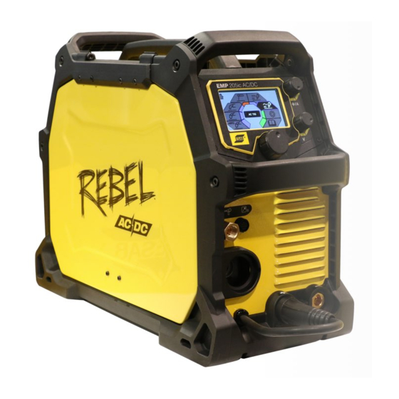
Page 22: Connections And Controls
5 OPERATION Connections and controls Figure 1. Front & rear views: Model EMP 205ic AC/DC Knob for current or wire feed speed Polarity changeover cable selection Knob for voltage selection Display Main knob for menu navigation Gas inlet for MIG/MAG... -
Page 23: Connection Of Welding And Return Cables
(12), on rear panel, to a regulated shielding gas supply. Connect the work return lead to the return-cable terminal (9). Connect the torch connector to the torch connection (6) (see Figure 1). 0463 652 001 - 23 - © ESAB AB 2018... -
Page 24: Polarity Change
The curves below show the maximum voltage and amperage output capabilities of the power source for three common welding process settings. Other settings result in curves that fall between these curves. A= Welding current (AMPS), V = Output voltage 0463 652 001 - 24 - © ESAB AB 2018... -
Page 25: Smaw (Stick) 120
5 OPERATION 5.5.1 SMAW (Stick) 120 V 5.5.2 SMAW (Stick) 230 V 0463 652 001 - 25 - © ESAB AB 2018... -
Page 26: Gmaw (Mig) 120
5 OPERATION 5.5.3 GMAW (MIG) 120 V 5.5.4 GMAW (MIG) 230 V 0463 652 001 - 26 - © ESAB AB 2018... -
Page 27: Gtaw (Dc Tig) 120
5 OPERATION 5.5.5 GTAW (DC TIG) 120 V 5.5.6 GTAW (DC TIG) 230 V 0463 652 001 - 27 - © ESAB AB 2018... -
Page 28: Gtaw (Ac Tig) 120
5 OPERATION 5.5.7 GTAW (AC TIG) 120 V 5.5.8 GTAW (AC TIG) 230 V 0463 652 001 - 28 - © ESAB AB 2018... -
Page 29: Duty Cycle
A different combination of duty cycle and welding current can be selected. Use the graphs below to determine the correct duty cycle for a given welding current. Figure 5. Plotting duty cycle for 120 V 0463 652 001 - 29 - © ESAB AB 2018... -
Page 30: Removing/Installing Bobbin
If installing aluminum wire, see "Welding with aluminum wire" section. The EMP 205ic AC/DC will handle the two smaller bobbin sizes of 4 in. (100 mm ), and 8 in. (200 mm). See "TECHNICAL DATA" chapter for suitable wire dimensions for each wire type. 0463 652 001 - 30 - © ESAB AB 2018... - Page 31 Do not place or point the torch near the face, hand or body as this may result in injury. NOTE! Make sure the correct wire-feed rollers are selected. NOTE! Use the correct contact tip in the welding torch for the wire diameter used. 0463 652 001 - 31 - © ESAB AB 2018...
-
Page 32: Removing Wire
Figure 9. Path of wire through wire feed assembly Wire from bobbin Wire to torch Pressure arm (shown raised) Tension knob assembly (shown lowered) 0463 652 001 - 32 - © ESAB AB 2018... - Page 33 5 OPERATION Locate the wire-feed assembly and its tension-knob. Figure 10. Wire-feed assembly part names Tension knob Inlet wire-guide Outlet wire-guide MIG torch locking knob Wire-feed roller 0463 652 001 - 33 - © ESAB AB 2018...
-
Page 34: Installing Wire
Pull the length of old wire out of the torch assembly from either end of the torch assembly. 5.7.2 Installing wire Disconnect the electrical power source from the unit. Open the wire-bobbin side cover of the EMP unit. Install the new bobbin (see "Removing/installing bobbin" section). 0463 652 001 - 34 - © ESAB AB 2018... -
Page 35: Welding With Aluminum Wire
Order the following accessories: • Torch teflon conduit liner (PTFE liner), 10 ft (3 m): See PARTS section (Wire liner Table) in the ESAB Torch Instruction Manual (see Note above). • Teflon coated output wire-guide tube (select size to match wire from Table in Appendix C). -
Page 36: Removing/Installing Wire-Feed Roller
“DEFAULT” and as “ACCESSORY”). Change the feed rollers to match the wire size/type on the wire bobbin. See Appendix C for feed roller selection. Figure 13 shows location of wire-feed rollers. The pressure rollers are not replaced. 0463 652 001 - 36 - © ESAB AB 2018... -
Page 37: Removing Wire-Feed Roller
If new rollers are being installed select the correct size and type (steel or aluminum) for wire being installed (see Appendix C). Disconnect the electrical power source from the unit. Open the cover on the wire-bobbin side of the EMP unit. 0463 652 001 - 37 - © ESAB AB 2018... - Page 38 When removing the roller be careful not to lose the drive-shaft key on the motor shaft. Failure to comply will render the entire unit useless until this part is replaced. 0463 652 001 - 38 - © ESAB AB 2018...
-
Page 39: Installing Wire-Feed Roller
Adjust the wire-feed pressure by adjusting the tension on the wire at the wire-feed rollers by turning the tension knob using the procedure in "Setting wire-feed pressure" section. Close the cover on the wire-bobbin side of the EMP unit. 0463 652 001 - 39 - © ESAB AB 2018... -
Page 40: Control Panel
MMA mode DC TIG mode AC TIG mode Settings User manual Dialogue box sMIG mode: Basic Home screen Information Memory Material selection Wire-feed speed selection Material thickness indicator Dialogue box 0463 652 001 - 40 - © ESAB AB 2018... -
Page 41: Smig Mode: Advanced
Manual MIG mode: Advanced Home screen Information Memory Material selection Parameter Wire-feed speed Voltage adjustment Dialogue box Flux cored wire mode: Basic Home screen Information Memory Wire-feed speed Voltage adjustment Dialogue box 0463 652 001 - 41 - © ESAB AB 2018... -
Page 42: Flux Cored Wire Mode: Advanced
Power-supply output voltage (Open Circuit Voltage or Arc) Arc ON/OFF Dialogue box Blue changes to orange when output is "hot". 6.11 DC TIG mode: Basic Home screen Information Memory Pulse Amperage Dialogue box 0463 652 001 - 42 - © ESAB AB 2018... -
Page 43: Dc Tig Mode: Advanced
Memory Amperage Dialogue box 6.14 AC TIG mode: Advanced Home screen Information Memory Parameter Amperage Balance Dialogue box 6.15 Settings Reset modes Inch/Metric Basic/Advanced Language Information Home screen Dialogue box 0463 652 001 - 43 - © ESAB AB 2018... -
Page 44: User Manual Information
ON: burnback set to keep the wire from zero freezing in the weld OFF: burnback set to puddle non-zero. Information Wire feed speed MIG Torch Spot time on adjustment 0463 652 001 - 44 - © ESAB AB 2018... - Page 45 Memory Mode Settings on user Cancel manual menu Spool torch Remote (Not all markets) Settings Foot control 2T, Trigger On/OFF Volts 4T, Trigger User manual on main Hold/Lock menu 0463 652 001 - 45 - © ESAB AB 2018...
- Page 46 Upslope, Unit of Measure Sloping the current up over a period of time at the beginning of the weld cycle Wire diameter Bead profile, concave Bead profile, convex 0463 652 001 - 46 - © ESAB AB 2018...
-
Page 47: Dc Tig Pulse
Peak Time (%): The peak time is the time at which the DC TIG Pulse waveform is at peak current. Peak time is adjusted in the percentage quantity of PPS. Can be adjusted between 1 and 99 %. 0463 652 001 - 47 - © ESAB AB 2018... - Page 48 Below picture illustration shows the navigation/setup of DC TIG Pulse in advanced mode (A-B-C-D-E-F-G-H-I-J). Below picture illustration shows an example of DC TIG output current ideal waveforms in Basic and Advanced modes. 0463 652 001 - 48 - © ESAB AB 2018...
-
Page 49: Ac Tig Welding
In other words the arc cone is much tighter at 400 Hz and focused at the same spot the tungsten electrode is pointing than the arc cone operating at 60 Hz. 0463 652 001 - 49 - © ESAB AB 2018... - Page 50 Another example; in the case of Offset set to +15 A with a user set current of 104 A, the weld current drives to EP = 119 A and EN = 89 A as shown in the pictures below. Below picture illustration shows the navigation/setup of AC TIG Welding in advanced mode (A-B-C-D-E-F-G-H-I-J-K). 0463 652 001 - 50 - © ESAB AB 2018...
- Page 51 6 CONTROL PANEL Below picture illustration shows an example of AC TIG output current ideal waveforms in Basic and Advanced modes. 0463 652 001 - 51 - © ESAB AB 2018...
-
Page 52: Lift-Tig Welding
6 CONTROL PANEL 6.20 Lift-TIG welding 2-stroke and 4-stroke welding process illustrated The trigger is used and some current flows already when lifting away the electrode to strike 0463 652 001 - 52 - © ESAB AB 2018... - Page 53 The shielding gas will continue to flow in order to protect the weld and the tungsten electrode. A = Gas pre-flow C = Slope down B = Slope up D = Gas post-flow 0463 652 001 - 53 - © ESAB AB 2018...
-
Page 54: Maintenance
There are no user serviceable parts inside of the power supply side of the EMP unit. Any need for service on the electronics/electrical-power side should be referred to the nearest ESAB service center. Routine maintenance Maintenance schedule during normal conditions:... -
Page 55: Wire-Feeder Assembly Maintenance
Recording the undisturbed scale number in the previous step facilitates the process at the end of the procedure to accurately set the tension. 0463 652 001 - 55 - © ESAB AB 2018... -
Page 56: Emp-Unit Power Side Maintenance
Because of the electro-static sensitive components and exposed circuit boards any maintenance on this side should be done by an authorized ESAB service technician. 0463 652 001 - 56 -... -
Page 57: Torch Liner Maintenance
Re-install the liner. Re-install the wire through the wire-feed assembly until visible at the torch tip. Verify that the wire does correctly feed out of the torch. 0463 652 001 - 57 - © ESAB AB 2018... -
Page 58: Troubleshooting
Preliminary checks Try these checks and inspections before sending for an authorized service technician. Before attempting to troubleshoot the ESAB Rebel it is recommended to first perform a WELD DATA RESET (navigate to HOME/SETTING/RESET/WELD DATA RESET). A WELD DATA RESET of the system will restore the unit to its default welding condition. - Page 59 See the "Duty cycle" section in the "OPERATION" chapter. • Make sure the air inlets or outlets are not clogged. • Make sure fans are operating when welding. 0463 652 001 - 59 - © ESAB AB 2018...
-
Page 60: User Interface (Ui) Software Displayed Error Codes
The image read from the flash is corrupted Failed two attempts of saving user memory to permanent memory in SPI Flash. Failed two attempts of recovering user memory permanent memory from SPI Flash. 0463 652 001 - 60 - © ESAB AB 2018... -
Page 61: Ordering Spare Parts
Spare parts and wear parts can be ordered through your nearest ESAB dealer, see the back cover of this document. When ordering, please state product type, serial number, designation and spare part number in accordance with the spare parts list. -
Page 62: Diagram
DIAGRAM DIAGRAM Functional block diagram Schematic 0463 652 001 - 62 - © ESAB AB 2018... -
Page 63: Ordering Numbers
ORDERING NUMBERS ORDERING NUMBERS Ordering no. Description Note 0558 102 553 EMP 205ic AC/DC Bobbin size 4–12 in. (100–300 mm) 0463 661 001 Spare Parts List 0463 652 001 - 63 - © ESAB AB 2018... -
Page 64: Wear Parts
Feed roll “V" groove Fe/SS 0.024" (0.6 mm) 0.030" (0.8 mm) 0558 102 329 Locking knob 0558 102 331 Pressure arm assembly 0558 102 332 MIG torch locking knob 0558 102 329 Tension knob assembly 0463 652 001 - 64 - © ESAB AB 2018... -
Page 65: Accessories
Accomodates maximum 7 in. (177.8 mm) diameter cylinder W4014450 Foot control Contactor on/off and current control with 15 ft (4.6 m) cable and 8-pin male plug 0558102491 Rebel single cylinder cart Accommodates 1 × 9 in. (228.6 mm) diameter cylinder 0463 652 001 - 65 - © ESAB AB 2018... - Page 66 Tweco® 200 A electrode holder & lead assembly, 13 ft (4 m), 50 mm dinse WS200G10 Tweco® 200 A ground clamp & lead assembly, 10 ft (3 m), 50 mm dinse W4013900 Gas hose, 12.5 ft (3.8 m) Male 5/8-18UNF W4014000 Power adapter (230 V – 120 V, 15 A) 0463 652 001 - 66 - © ESAB AB 2018...
- Page 67 PURCHASE 0558 102 588 TUBE, WIRE GUIDE .052 (1.4) – .062 (1.6), OPTIONAL FOR ALUM PURCHASE * DEFAULT (size included in package) ** ACCESSORY (optional size included with each model) 0463 652 001 - 67 - © ESAB AB 2018...
- Page 68 For contact information visit esab.com ESAB AB, Lindholmsallén 9, Box 8004, 402 77 Gothenburg, Sweden, Phone +46 (0) 31 50 90 00 http://manuals.esab.com...
Need help?
Do you have a question about the EMP 205ic AC/DC and is the answer not in the manual?
Questions and answers