
Summary of Contents for Glendinning EEC4
- Page 1 EEC4 Electronic Engine Controls by Glendinning Installation Manual v3.3 Glendinning Marine Products, Inc. 740 Century Circle Conway, SC 29526 www.glendinningprods.com...
- Page 2 MANUAL REVISIONS REVISION PAGE # DESCRIPTION DATE of CHANGE Initial startup of document JULY 2006...
-
Page 3: Table Of Contents
1.0 Installing the EEC4 ........ - Page 4 EEC4 Installation Manual A word about the Symbols used in the Manual When driving from one destination to another, road signs prove to be invaluable. Road signs are an important source of information. For example, road signs can warn you about potential problems ahead to help divert certain disaster or they can let you know where to turn off for a rest or a meal.
-
Page 5: Installing The Eec4
Terminating Resistor 1.1 Pre-Installation Planning Before beginning the installation of the Glendinning EEC4 System, it is very important that some thought be given to the overall installation. The following should be considered: — Control Processor location — Power / Battery supply... - Page 6 STRONGLY RECOMMENDED. If the EEC4 system is only connected to a single battery power source, intermit- tent drops in battery voltage — perhaps during engine start — can cause intermittent failures of the EEC4 system. NOTE: Vessels battery Ensure that the power supply to the control system ground must be connected together.
- Page 7 Station Communications Cable — CANbus Network Design The EEC4 system utilizes a CANbus digital communications system to link the components in the con- trol system — Control Processor (CP) and Control Heads (CH). There are various ways in which the Station Communications cable can be connected depending on the application.
- Page 8 EEC4 Installation Manual Single Station Layout Single cable connects control head to control processor. Terminating resistor installed at open communications port at control head. Terminating resistor installed at open communications port at control processor. The Dual Station Layout illustrates how both control stations are connected to the control processor by separate cables.
-
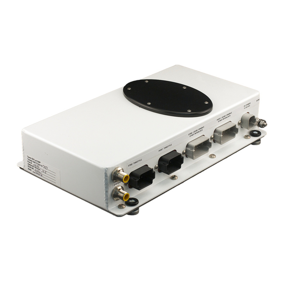
Page 9: Mounting The Control Processor
1.2 Mount the Control Processor EEC4 Control Processor Follow these steps to install the EEC4 Control Processor: STEP 1: The Control Processor can be mounted anywhere in the engine room providing that the Processor is reasonably accessible mounting points... -
Page 10: Mounting The Control Head(S)
Station ID (multiple station applications) A total of six (6) control stations may be added to the EEC4 system. In a multi-station control system, all of the control handles are identical from a hardware point of view. However, there is a software con- figuration that must be completed to designate the “Station Identifier (ID) for each station. -
Page 11: Station Communication Cable Installation
Section 1.0 — Installing the EEC4 1.4 Station Communication Cable Installation Install the Station Communication cables between the Control Processor and Control Head(s) as pre- viously discussed in Section 3.1. Station communication cables are available in 20, 30, 40. or 60 foot lengths. - Page 12 EEC4 Installation Manual Gear Connectors on Control System Enable TCPM are colored gray Connector Gear Connector Throttle Connector on harness Throttle & Transmission Harness (each engine requires 1 harness) Throttle Connector on harness Gear Connectors (2) Start Interlock Throttle Connectors on...
- Page 13 Section 1.0 — Installing the EEC4 IMPORTANT — When routing and connecting the throttle and gear harness, BE SURE TO: Insert the plug completely into the receptacle on the control processor and the engine. You should hear a “click” when the plug is fully inserted.
-
Page 14: Dc Power Input
EEC4 Installation Manual Connect control system to vessel control system enable plug adapter harness enable harness where jumper was removed piggy-back connector insert 4-pin control system plug Connect jumper to “piggy-back” to vessel connector on control system adapter harness piggy-back... -
Page 15: System Test & Checkout
Battery negative terminals should be connected to Bonding system also. Negative Lead—Negative wire from EEC4 system is connected to single battery negative. Positive Leads—Power should be connected from Battery positive terminal or disconnect switch (battery side of switch) to CP via 10 amp fuse / circuit breaker. - Page 16 EEC4 Installation Manual Operational Checks A. General Functions Turn ON System by turning ON one of the engine ignition switches. The Control Head ACTIVE light and the Neutral gear indicating lights should immediately illuminate. — If the Control Head lights DO NOT come on immediately, but all the lights flash after about 20 sec- onds, the system is in alarm mode and the problem is most likely due to a network communications problem.
- Page 17 Section 1.0 — Installing the EEC4 Sea Trials At the conclusion of the Operational Tests described above, the EEC4 system is ready for operation. There are no functional tests that need to be completed at sea trial to validate correct system installa- tion.
- Page 18 EEC4 Installation Manual Move the STBD engine handle by itself — both STBD and PORT engines will respond simulta- neously. Bump Mode — While the boat is underway and Each time that the control head buttons are is in a safe area that will allow maneuvering, and pressed —...
-
Page 19: Appendix / References
Section 2.0 — Appendix / Reference 2.0 Appendix / Reference The Appendix / Reference section is divided as follows: 2.1 Wiring Diagrams (many other engine layouts available, contact GMP) A. Wiring Diagram - Cummins QSB / QSC ..........17 B. - Page 20 EEC4 Installation Manual...
-
Page 21: Wiring Diagram - Cummins Qsb / Qsc
Section 2.0 — Appendix / Reference STBD Throttle PORT Throttle STBD Gear PORT Gear DC PWR Gear Harness To Start Interlock Cntr. To Throttle Cntr. To Ign. Switch Cntr. Gear Harness To Start Interlock Cntr. To Throttle Cntr. To Ign. Switch Cntr. -
Page 22: Harness - Cummins Qsb / Qsc
EEC4 Installation Manual ETS Control System Harnesses - Cummins DC Power Harness 30' long (9 meters) C P End Battery Positive #1 Duetsch 4 pos. Black (Red wire) Battery Positive #2 (Red wire) (Noise Supression devices) Battery Negative (yellow wire) -
Page 23: Cp Pinout Description
Section 2.0 — Appendix / Reference Control Processor Pinout Description DC Power Connector (4 pin-Gray) Bond (1) Battery Positive 1 (3) Battery Ground 1 (2) Battery Positive 2 (4) Battery Ground 2 (optional, if required) DC Power PORT Gear / Start Interlock / CP Enable Connector (12 pin-Gray) (7) Spare Output (N.O.) (1) PORT Ahead gear Positive (+) (8) Not Used... -
Page 24: Dimensional Drawings / Cutout Templates
EEC4 Installation Manual Control Processor Dimensions 2.95" 3.5" (75mm) (88mm) 6.38" (162mm) 7.88" (200mm) 7.13" (181mm) Bond Connection DC Power Input Transmission/ Start Interlock/ Enable 10.5" 12.75" (267mm) (324mm) Throttle Ouput Station Harness Connections... -
Page 25: Control Head Dimensions
Section 2.0 — Appendix / Reference Control Head Dimensions (Top Mount) 5.8" 4.25" (146.6mm) (107.9mm) 5.8" (146.6mm) 6.85" (173.9mm) 1.12" 2.27" (28.5mm) (57.7mm) 1/4 Mounting Stud 2.125" long 2 places 10.31" (261.8mm) - Page 26 EEC4 Installation Manual...
-
Page 27: Cutout Template For Control Head
Section 2.0 — Appendix / Reference Cutout Template for Control Head (Top Mount) 3.25"... - Page 28 EEC4 Installation Manual...
-
Page 29: Control Head Configuration
Section 2.0 — Appendix / Reference 2.3 Control Head Configuration In order for each Control Head to communicate with the Control Processor, each Control Head must have a unique Handle Identifier. If you purchased a complete system, configuration and handle identification was performed by the factory. If you purchased a control head separately, you will NEED to set the handle identifier for that control station. - Page 30 EEC4 Installation Manual ACTION RESULT Press & Release LEDs ON ACTIVE button until desired handle ID is PORT NEUTRAL achieved — see chart at right for ID# and cor- ACTIVE responding LED that is illuminated PORT NEUTRAL & ACTIVE WARM PORT NEUTRAL &...
-
Page 31: System Configuration
Section 2.0 — Appendix / Reference 2.4 System Configuration Configuration of the EEC system was performed at GMP from the information the ship operator gave at the time the order was placed. Changes to the Control Processor configuration, although not frequently done, can be made to suit operator preference and is entered from the control head keypad. -
Page 32: Throttle Delay Options
EEC4 Installation Manual Throttle Delay Options The Throttle Delay Option allows you to configure the EEC system to delay throttle output as you shift from Neutral, past in-gear idle, and into the throttle range. Throttle Neutral range Configurable 0-2.5 second... -
Page 33: Gear Delay Options
Section 2.0 — Appendix / Reference Gear Delay Options The Gear Delay Option allows you to configure the EEC system to remain in gear when the system goes from the throttle range to neutral, to allow throttle to reach idle before shifting transmission. Neutral Throttle Throttle... -
Page 34: System Startup Options
EEC4 Installation Manual System Startup Options The System Startup Option allows you to configure the EEC system to enter WARM Mode or Normal RUN Mode at startup (power ON). the transmission will immediately respond to the any movement of the... -
Page 35: Station Transfer Options
Section 2.0 — Appendix / Reference Station Transfer Options The Station Transfer Option allows you to configure the EEC system to transfer station control under- way above idle or with handles at the Neutral position only. NOTE: Active Station can be at any handle position during station transfer Inactive Station “taking control”... -
Page 36: Return Settings To Defaults
EEC4 Installation Manual Return System Settings to Default Option The Return System Settings to Default Option allows you to return the system to it’s factory default set- tings. To Change System Startup Setting Follow These Steps: Enter Configuration Mode as described in section 2.4A (pg. 29)
Need help?
Do you have a question about the EEC4 and is the answer not in the manual?
Questions and answers