Advertisement
Quick Links
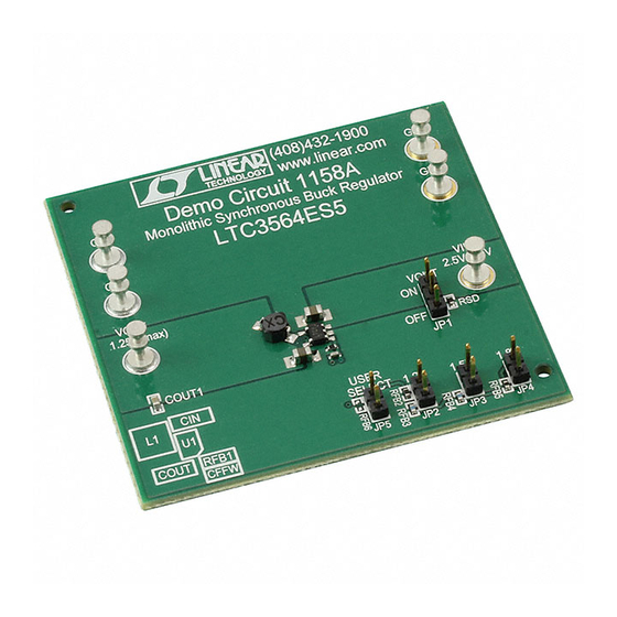
QUICK START GUIDE FOR DEMONSTRATION CIRCUIT 1158A
DESCRIPTION
Demonstration circuit DC1158A is a high efficiency
monolithic synchronous buck regulator using a
constant frequency, current mode architecture fea-
turing LTC3564. Its high switching frequency of
2.25MHz allows the use of small surface mount
inductors and capacitors. Supply current during
operation is only 20uA dropping to below 1uA in
shutdown. The 2.5V to 5.5V input voltage range
Table 1.
Performance Summary (T
PARAMETER
Input Voltage
Output Voltage V
OUT
Maximum Output Current
DC Supply Current
Nominal Switching Frequency
QUICK START PROCEDURE
The DC1158A is easy to set up to evaluate the
performance of the LTC3564. For a proper
measurement equipment configuration, set up
the circuit according to the diagram in Figure 2.
NOTE: When measuring the input or output volt-
age ripple, care must be taken to avoid a long
ground lead on the oscilloscope probe. Measure
the input or output voltage ripple by touching the
probe tip directly across the V
terminals. See the Measurement Equipment Set-
up diagram in Figure 1 for proper scope probe
technique.
Please follow the procedure outlined below for
proper operation.
1. Connect the input power supply to the V
and GND terminals. Connect the load between
MONOLITHIC SYNCHRONOUS BUCK REGULATOR
= 25ºC)
A
CONDITION
I
=0A to 1.25A
OUT
V
= 0.5V or V
= 90%, I
FB
OUT
V
= 0.6V or V
= 100%
FB
OUT
or V
and GND
IN
OUT
IN
makes the LTC3564 ideally suited for single Li-Ion
battery-powered or 3.3V to 5V input voltage appli-
cations. 100% duty cycle provides low dropout
operation, extending battery life in portable sys-
tems. Automatic Burst Mode® operation increases
efficiency at light loads, further extending battery
runtime. Gerber files for this circuit are avail-
able.
Call
VALUE
2.5V to 5.5V
V
± 0.5%
OUT
1.25A
= 0A
300µA
OUT
2.25MHz
the V
and GND terminals. Refer to Figure 2
OUT
for the proper measurement equipment setup.
2. Before proceeding to operation, insert
jumper shunt XJP1 into the OFF position and
insert jumper shunt into XJP2, XJP3 or XJP4
for voltages of 1.2V, 1.5V or 1.8V respectively.
Set the load output current to less than 1.25A.
An optional output voltage can be set by popu-
lating resistor RFB6, removing RFB5 and mov-
ing the shunt jumper to JP5.
3. Apply 5V at V
. Measure V
IN
read 0V. If desired, one can measure the shut-
down supply current at this point. The supply cur-
rent will be about 1 µA in shutdown.
4. Turn on V
by changing shunt XJP1 from
OUT
the OFF position to the ON position. The out-
put voltage should measure according to the
LTC3564
the
LTC
Factory.
; it should
OUT
1
Advertisement

Related Manuals for Linear Technology 1158A


Summary of Contents for Linear Technology 1158A
- Page 1 QUICK START GUIDE FOR DEMONSTRATION CIRCUIT 1158A MONOLITHIC SYNCHRONOUS BUCK REGULATOR LTC3564 DESCRIPTION Demonstration circuit DC1158A is a high efficiency makes the LTC3564 ideally suited for single Li-Ion monolithic synchronous buck regulator using a battery-powered or 3.3V to 5V input voltage appli- constant frequency, current mode architecture fea- cations.
- Page 2 QUICK START GUIDE FOR DEMONSTRATION CIRCUIT 1158A MONOLITHIC SYNCHRONOUS BUCK REGULATOR voltage set by the shunt jumper in XJP2, XJP3 6. Vary the V load current from 0 to 1.25A, or XJP4. and the output voltage should be within a toler- ance of +/- 0.5%.
- Page 3 QUICK START GUIDE FOR DEMONSTRATION CIRCUIT 1158A MONOLITHIC SYNCHRONOUS BUCK REGULATOR...
Need help?
Do you have a question about the 1158A and is the answer not in the manual?
Questions and answers