Table of Contents
Advertisement
Quick Links
Advertisement
Table of Contents

Related Manuals for PERCo IRP-01

Summary of Contents for PERCo IRP-01
- Page 2 Reader Post IRP-01 Certificate and Operation Manual TC RU C-RU.МЛ02.В.00274 ТУ 4372-050-88226999-2014...
-
Page 3: Table Of Contents
Safe installation ....................11 Safe operation ..................... 11 Installation procedure ....................12 Features of installation ..................12 Tools and equipment required for installation ............12 Required cables ....................12 Assembly sequence .................... 13 Troubleshooting ......................15 Perco warranty ......................15... -
Page 4: General Information
LCD indicating operation modes of ACS controller. IRP-01 reader post is designed as an up-market model to fit the highest requirements for design and comfort (governmental offices, banks, administrative buildings, sport centers, airports, etc.). -
Page 5: Technical Specifications
Certificate & Operation Manual 2 TECHNICAL SPECIFICATIONS Rated operating voltage ..................12VDC Operating voltage limits .................. 10.8–14VDC Consumption current ..................max. 150 mA Power consumption ....................max. 2 W Card reading distance at the rated operating voltage for different card types: HID ProxCard II cards ................. -
Page 6: Product Description
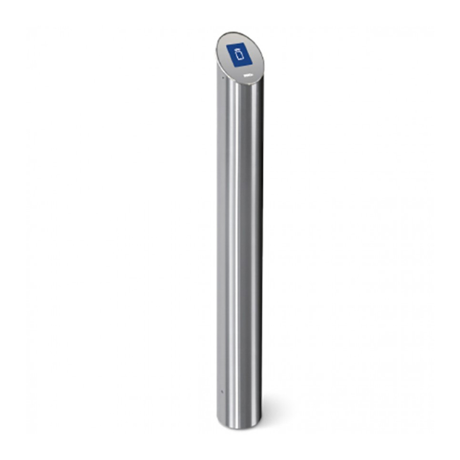
Reader post consists of stainless steel tube with reader board and LCD. Delivery set also contains mounting base that the reader post housing is attached to. The reader is equipped with integrated sound indicator. Code reading is confirmed by a short sound signal. Figure 1. IRP-01 overall view and dimensions... -
Page 7: Operating Principle
Certificate & Operation Manual The board of the reader is shown on Fig. 2. Figure 2. The board of the reader The board contains: ХТ1 – connectors for power cables. ХТ3 – connector for connection via RS-485 interface. ХТ4 and ХТ5 – connectors for connection via Wiegand interface. ХР5 –... -
Page 8: Data Transmitting Via Wiegand Interface
IRP-01 Reader Post Reader transforms the received signal in accordance with an external device interface and sends it to controller of external device via RS-485 or Wiegand interfaces. Data is transmitted to the external controller at one time, asynchronously, at the moment of first positive signal receipt from identifier. -
Page 9: Configuration
To operate the reader in RS-485 mode the switch №1 of DIP-switch SA1, located on the board of the reader (see Fig. 2), shall be set in ON position. When the reader is connected via RS-485 interface, it can be used as an external reader for PERCo Web controllers. 5.1.1 Selection of reader number When readers are connected to RS-485 interface, they need to have different numbers (switch 2) to determine the direction of passage. -
Page 10: Indication
IRP-01 Reader Post 5.1.2 Indication When operated with PERCo Web controllers, LCD of the reader show the following indication of controller operation modes: “Control” mode indication – general background and an appearing hand with a card, showing that it is necessary to present a card “Open”... -
Page 11: Operation Of Reader In Wiegand Mode
Certificate & Operation Manual 5.2 Operation of reader in Wiegand mode To operate the reader in Wiegand mode the switch 1 of DIP-switch SA1, located on the board of the reader (see Fig. 2), shall be set in OFF position. If the reader is connected to Wiegand interface, it can be used an external reader for ACS controllers. -
Page 12: Safety Requirements
IRP-01 Reader Post Table 4. Selection of output data format of the reader on DIP-switch SA1 Switch Output data format Wiegand 26 Wiegand 37 Wiegand 42 OFF OFF Wiegand OFF OFF OFF 6 SAFETY REQUIREMENTS 6.1 Safe installation Attention! • All work should be carried out only when the power is off and power supply is disconnected from the mains. -
Page 13: Installation Procedure
Certificate & Operation Manual 7 INSTALLATION PROCEDURE 7.1 Features of installation The following factors must be considered: • Readers shall be installed close to the operating device; • Close electric interference sources shorten card reading distance, therefore reader must be installed at min. 1 m whilst its cable laid at min. 30 cm distance from computer monitors, electric generators and motors, ac relays, thyristor light regulators, ac lines, computer and telephone signals;... -
Page 14: Assembly Sequence
IRP-01 Reader Post 7.4 Assembly sequence Follow this sequence during installation of the reader: 1. Unpack the box with equipment, check carefully the delivery set. 2. Choose the place for installation in accordance with recommendations given in Section 7.1. 3. Mark the mounting holes in the floor as per 5, and also mark electrical conduit for the cable from ACS controller to the reader post. - Page 15 14. Connect the cable to the PERCo Web controller or ACS according to layout given on Fig. 6 or Fig. 7. Figure 5. Mounting hole pattern for IRP-01 installation...
-
Page 16: Troubleshooting
RS-485 or distribution of RS-485 indication on this reader Wiegand In an unlikely event of other faults please consult the PERCo Technical Support Department. 9 PERCO WARRANTY PERCo (the Manufacturer) warrants that the IRP-01 reader post complies with applicable statutory safety requirements and electromagnetic compatibility provided that the instructions on storage, installation and operation, given in the Certificate &... - Page 17 Product in case they are in compliance with those stated by the Manufacturer. The Manufacturer does not guarantee that the Product purchased will meet Customer’s requirements and expectations. PLEASE NOTE THAT PERCo PRODUCES TECHNICALLY SOPHISTICATED PRODUCTS THAT, IF NOT FAULTY, CANNOT BE RETURNED BACK IF BY SOME REASON...
- Page 18 WARRANTY CARD IRP-01 reader post Serial number Date of manufacture « » ________________201__ Quality control seal _____________________________________________ Date of sale « » ________________201__ ____________________________________ (signature, seal) Cutting line Warranty repair coupon IRP-01 reader post Serial number Date of manufacture «...
- Page 21 PERCo P.O. Box 87, Saint Petersburg, 194295, Russia Tel: +7 812 321 61 72 Fax: +7 812 292 36 08 E-mail: export@perco.ru support@perco.ru www.perco.com...
- Page 22 export@perco.ru...
Need help?
Do you have a question about the IRP-01 and is the answer not in the manual?
Questions and answers