
Related Manuals for Omron NX-AD series


Summary of Contents for Omron NX-AD series
- Page 1 Machine Automation Controller NX-series Analog I/O Units User’s Manual for Analog Input Units and Analog Output Units NX-AD NX-DA Analog I/O Units W522-E1-07...
- Page 2 No patent liability is assumed with respect to the use of the information contained herein. Moreover, because OMRON is constantly striving to improve its high-quality products, the information contained in this manual is subject to change without notice. Every precaution has been taken in the preparation of this manual. Neverthe- less, OMRON assumes no responsibility for errors or omissions.
-
Page 3: Introduction
Introduction Introduction Thank you for purchasing an Analog Input Unit or Analog Output Unit. This manual contains information that is necessary to use these Analog Input Units and Analog Output Units, which are classified as NX-series Analog I/O Units. Please read this manual and make sure you understand the functionality and performance of the NX-series Analog I/O Unit before you attempt to use it in a control system. -
Page 4: Table Of Contents
CONTENTS CONTENTS Introduction ......................1 Intended Audience............................1 Applicable Products ............................. 1 Relevant Manuals ..................... 6 Manual Structure ...................... 7 Page Structure and Icons ..........................7 Special Information ............................8 Precaution on Terminology .......................... 8 Terms and Conditions Agreement ................ 10 Warranty, Limitations of Liability ........................ - Page 5 CONTENTS Model List..........................1-7 1-3-1 Model Notation..........................1-7 1-3-2 Analog Input Units ........................1-9 1-3-3 Analog Output Units........................1-11 List of Functions........................1-12 1-4-1 Analog Input Units ........................1-12 1-4-2 Analog Output Units........................1-13 Support Software......................... 1-14 Section 2 Specifications General Specifications ......................2-2 Individual Specifications ......................
- Page 6 CONTENTS Section 6 Analog Input Units Types of Analog Input Units ....................6-2 Input Range and Converted Values ..................6-4 Specifications of I/O Data ..................... 6-6 6-3-1 Allocable I/O Data ........................6-6 List of Settings........................6-8 Function ..........................6-12 6-5-1 List of Analog Input Unit Functions ...................
- Page 7 CONTENTS Maintenance Procedures ...................... 9-5 Appendices A-1 Data Sheet ..........................A-2 A-1-1 Model List ........................... A-2 A-1-2 Analog Input Units ........................A-4 A-1-3 Analog Output Units........................A-24 A-2 Dimensions ..........................A-37 A-2-1 Screwless Clamping Terminal Block Type ................A-37 A-3 List of NX Objects........................A-39 A-3-1 Format of Object Descriptions ....................
-
Page 8: Relevant Manuals
Relevant Manuals Relevant Manuals The table below provides the relevant manuals for the NX-series Analog I/O Units. Read all of the manuals that are relevant to your system configuration and application to make the most of the NX-series Analog I/O Units. Other manuals, such as related product manuals, are necessary for specific system configurations and applications. -
Page 9: Manual Structure
Manual Structure Manual Structure Page Structure and Icons The following page structure and icons are used in this manual. Level 1 heading 4 Installation and Wiring Level 2 heading Level 3 heading Mounting Units Level 2 heading Gives the current Level 3 heading headings. -
Page 10: Special Information
Manual Structure Special Information Special information in this manual is classified as follows: Precautions for Safe Use Precautions on what to do and what not to do to ensure safe usage of the product. Precautions for Correct Use Precautions on what to do and what not to do to ensure proper operation and performance. Additional Information Additional information to read as required. - Page 11 Manual Structure • This user's manual refers to the built-in EtherCAT port on an NJ/NX-series Controller or NY-series Industrial PC as simple a built-in EtherCAT port. • This user's manual may omit manual names and manual numbers in places that refer to the user's manuals for CPU Units and Industrial PCs.
-
Page 12: Terms And Conditions Agreement
Omron’s exclusive warranty is that the Products will be free from defects in materials and workman- ship for a period of twelve months from the date of sale by Omron (or such other period expressed in writing by Omron). Omron disclaims all other warranties, express or implied. -
Page 13: Application Considerations
Disclaimers Performance Data Data presented in Omron Company websites, catalogs and other materials is provided as a guide for the user in determining suitability and does not constitute a warranty. It may represent the result of Omron’s test conditions, and the user must correlate it to actual application requirements. Actual perfor- mance is subject to the Omron’s Warranty and Limitations of Liability. -
Page 14: Safety Precautions
Safety Precautions Safety Precautions Definition of Precautionary Information The following notation is used in this manual to provide precautions required to ensure safe usage of the NX-series Analog Input Units and Analog Output Units. The safety precautions that are provided are extremely important to safety. Always read and heed the information provided in all safety precautions. -
Page 15: Warnings
Safety Precautions Warnings WARNING During Power Supply Do not touch the terminal section while power is ON. Electric shock may occur. Do not attempt to take any Unit apart. In particular, high-voltage parts are present in Units that supply power while power is sup- plied or immediately after power is turned OFF. -
Page 16: Cautions
Safety Precautions Voltage and Current Inputs Make sure that the voltages and currents that are input to the Units and slaves are within the specified ranges. Inputting voltages or currents that are outside of the specified ranges may cause accidents or fire. - Page 17 Safety Precautions Online Editing Execute online editing only after confirming that no adverse effects will be caused by devia- tions in the timing of I/O. If you perform online editing, the task execution time may exceed the task period, I/O may not be refreshed with external devices, input signals may not be read, and output timing may change.
-
Page 18: Precautions For Safe Use
Precautions for Safe Use Precautions for Safe Use Transporting • When transporting any Unit, use the special packing box for it. Also, do not subject the Unit to excessive vibration or shock during transportation. • Do not drop any Unit or subject it to abnormal vibration or shock. Doing so may result in Unit malfunction or burning. - Page 19 Precautions for Safe Use • Do not write on an NX Unit with ink within the restricted region that is shown in the following figure. Also do not get this area dirty. When the Unit is installed or removed, ink or dirt may adhere to the pins in the NX bus connector, which may result in malfunctions in the CPU Rack or the Slave Termi- nal.
- Page 20 Precautions for Safe Use Wiring • Double-check all switches and other settings and double-check all wiring to make sure that they are correct before turning ON the power supply. Use the correct wiring parts and tools when you wire the system. •...
- Page 21 Precautions for Safe Use Actual Operation • Before you start operation, always register the NX Units that are connected to the Communications Coupler Unit in the host communications master as the Unit Configuration Information. • Check the user program, data, and parameter settings for proper execution before you use them for actual operation.
- Page 22 Precautions for Safe Use Disposal • Dispose of the product according to local ordinances as they apply. NX-series Analog I/O Units User’s Manual for Analog Input Units and Analog Output Units (W522)
-
Page 23: Precautions For Correct Use
Precautions for Correct Use Precautions for Correct Use Storage, Mounting, and Wiring • Follow the instructions in this manual to correctly perform installation and wiring. • Do not operate or store the Units in the following locations. Doing so may result in malfunction, in operation stopping, or in burning. -
Page 24: Regulations And Standards
Concepts EMC Directives OMRON devices that comply with EU Directives also conform to the related EMC standards so that they can be more easily built into other devices or the overall machine. The actual products have been checked for conformity to EMC standards.*1 Whether the products conform to the standards in the system used by the customer, however, must be checked by the customer. -
Page 25: Conformance Requirement To Eu Directives
NX-series product must also comply with the standards, consult with your OMRON representative. Application conditions are defined according to the installation location. Application may not be possible for some installation locations. -
Page 26: Conformance To Kc Standards
Sellers and/or users need to take note of this. Software Licenses and Copyrights This product incorporates certain third party software. The license and copyright information associated with this software is available at http://www.fa.omron.co.jp/nj_info_e/. NX-series Analog I/O Units User’s Manual for Analog Input Units and Analog Output Units (W522) -
Page 27: Unit Versions
Unit Versions Unit Versions This section describes the notation that is used for unit versions, the confirmation method for unit ver- sions, and the relationship between unit versions and Support Software versions. Unit Versions A “unit version” has been introduced to manage the Units in the NX Series according to differences in functionality accompanying Unit upgrades. -
Page 28: Unit Versions And Support Software Versions
Gives the lot number of the Unit. DDMYY : Lot number, : Used by OMRON. “M” gives the month (1 to 9: January to September, X: October, Y: November, Z: December) The following information is provided in the notched area on the Unit. -
Page 29: Related Manuals
Related Manuals Related Manuals The following table shows related manuals. Use these manuals for reference. Manual name Cat. No. Model numbers Application Description NX-series Analog I/O W522 NX-AD Learning how to The hardware, setup methods, and Units User’s Manual for use NX-series functions of the NX-series Analog Input NX-DA... - Page 30 Related Manuals Manual name Cat. No. Model numbers Application Description NX-series Ether- W536 NX-EIC202 Learning how to The following items are described: the use an NX-series overall system and configuration meth- Net/IP Coupler Unit EtherNet/IP Cou- ods of an EtherNet/IP Slave Terminal User’s Manual pler Unit and Eth- (which consists of an NX-series Ether-...
- Page 31 Related Manuals Manual name Cat. No. Model numbers Application Description NY-series IPC Machine W556 NY512- Learning the basic An introduction to the entire NY-series system is provided along with the fol- Controller Industrial Box specifications of PC Hardware User’s the NY-series lowing information on the Industrial Box Manual Industrial Box PCs,...
- Page 32 Related Manuals *1. From revision 05 of this manual, information on the NX-series Temperature Input Units (NX-TS ) that were includ- ed in previous revisions was moved to the following manual: NX-series Analog I/O Units User’s Manual for Temperature Input Units and Heater Burnout Detection Units (Cat. No. W566). Accompanying that change, the name of this manual was changed from the NX-series Analog I/O Units User’s Manual (Cat.
-
Page 33: Terminology
Terminology Terminology Abbre- Term Description viation application layer status, AL status Status for indicating information on errors that occur in an application on a slave. CAN application protocol over Ether- A CAN application protocol service implemented on EtherCAT. CAN in Automation CiA is the international users' and manufacturers' group that develops and supports higher-layer protocols. - Page 34 Terminology Abbre- Term Description viation Operational A state in EtherCAT communications where SDO communications and I/O are possible. PDO communications An acronym for process data communications. Pre-Operational A state in EtherCAT communications where only SDO communications are possible with the slaves, i.e., no I/O can be performed. primary periodic task The task with the highest priority.
-
Page 35: Revision History
Revision History Revision History A manual revision code appears as a suffix to the catalog number on the front and back covers of the manual. Cat. No. W522-E1-07 Revision code Revision code Date Revised content April 2013 Original production June 2013 Corrected mistakes September 2013 •... - Page 36 Revision History NX-series Analog I/O Units User’s Manual for Analog Input Units and Analog Output Units (W522)
-
Page 37: Sections In This Manual
Sections in this Manual Sections in this Manual Features and System Appendices Configuration Index Specifications Part Names and Functions Installation and Wiring I/O Refreshing Analog Input Units Analog Output Units Troubleshooting Inspection and Maintenance NX-series Analog I/O Units User’s Manual for Analog Input Units and Analog Output Units (W522) - Page 38 Sections in this Manual NX-series Analog I/O Units User’s Manual for Analog Input Units and Analog Output Units (W522)
-
Page 39: Features And System Configuration
Features and System Configura- tion This section describes NX system configuration and the applications of the Analog Input Units and Analog Output Units. 1-1 Features and Applications ........1-2 1-1-1 Features of the Analog Input Units and Analog Output Units . -
Page 40: Features And Applications
1 Features and System Configuration Features and Applications This section describes the features and applications of the Analog Input Units and Analog Output Units. 1-1-1 Features of the Analog Input Units and Analog Output Units The Analog Input Units and Analog Output Units are used to process inputs and outputs of analog sig- nals. -
Page 41: Applications Of The Analog Input Units And Analog Output Units
1 Features and System Configuration Synchronous I/O with Refresh Cycle of the NX Bus When the NX-series CPU Unit or EtherCAT Coupler Unit is used together with NX Units that support synchronous I/O refreshing, the I/O control of multiple NX Units can be synchronized at the time to syn- chronize with the refresh cycle of the NX bus. -
Page 42: System Configuration
1 Features and System Configuration System Configuration NX Unit NX-series Analog Input Units and Analog Output Units can be connected to the following Units. • NX-series CPU Unit • NX-series Communications Coupler Unit The following explains the system configuration for each NX Unit connection destination. 1-2-1 System Configuration in the Case of a CPU Unit The following figure shows a system configuration when a group of NX Units is connected to an... -
Page 43: System Configuration Of Slave Terminals
1 Features and System Configuration Symbol Item Description Support Software A computer software application for setting, programming, debugging, and troubleshooting NJ/NX/NY-series Controllers. (Sysmac Studio) For an NX1P2 CPU Unit, this application performs setting operation by making a connection to a built-in EtherNet/IP port. 1-2-2 System Configuration of Slave Terminals A building-block remote I/O slave provided with a group of NX Units connected to a Communications... - Page 44 *1. An EtherCAT Slave Terminal cannot be connected to any of the OMRON CJ1W-NC 81/ 82 Position Control Units even though they can operate as EtherCAT masters. *2. The term Support Software indicates software that is provided by OMRON. If you connect to a master from another company, use the software tool corresponding to that master.
-
Page 45: Model List
1 Features and System Configuration Model List 1-3-1 Model Notation The model numbers of the Analog Input Units and Analog Output Units are assigned based on the fol- lowing rules. NX - - Unit type AD : Analog input DA : Analog output Number of points 2 : 2 points 3 : 4 points... - Page 46 1 Features and System Configuration Other Specifications Analog Input Units I/O refreshing method Switching Syn- chronous I/O Free-Run refresh- Resolution Conversion time Input method refreshing only Free-Run refresh- 1/8000 250 μs/point Single-ended 1/8000 250 μs/point Differential 1/30000 10 μs/point Differential *1.
-
Page 47: Analog Input Units
1 Features and System Configuration 1-3-2 Analog Input Units This section shows the specifications for Analog Input Units. Refer to A-1-2 Analog Input Units on page A-4 for details on the specifications of individual Analog Input Units. Analog Input Units (Screwless Clamping Terminal Block, 12 mm Width) Resolu- Input... - Page 48 1 Features and System Configuration Resolu- Input I/O refresh- Conver- Model Input range Reference tion method ing method sion time point Sin- NX-AD4203 gle-ende P. A-18 Free-Run 1/8000 250 μs/point refreshing NX-AD4204 P. A-19 4 to 20 mA Switching Differen- Synchronous tial NX-AD4208...
-
Page 49: Analog Output Units
1 Features and System Configuration 1-3-3 Analog Output Units This section shows the specifications for Analog Output Units. Refer to A-1-3 Analog Output Units on page A-24 for details on the specifications of individual Analog Output Units. Analog Output Units (Screwless Clamping Terminal Block, 12 mm Width) Resolu- Conversion... -
Page 50: List Of Functions
1 Features and System Configuration List of Functions This section provides an overview of functions that Analog Input Units and Analog Output Units have. Refer to the specifications of each model in A-1 Data Sheet on page A-2 for details on the functions. 1-4-1 Analog Input Units Function name... -
Page 51: Analog Output Units
1 Features and System Configuration 1-4-2 Analog Output Units Function name Description Reference Free-Run Refreshing With this I/O refreshing method, the refresh cycle of the NX 5-2-4 Free-Run bus and the I/O refresh cycles of the NX Units are asynchro- Refreshing on nous. -
Page 52: Support Software
1 Features and System Configuration Support Software The Support Software that is used depends on the system configuration. Support Software for a System Configured with a CPU Unit If your system is configured by connecting an NX Unit to a CPU Unit, the Sysmac Studio is used as the Support Software. -
Page 53: Specifications
Specifications This section describes the general specifications and individual specifications of the Analog Input Units and Analog Output Units. 2-1 General Specifications ......... 2-2 2-2 Individual Specifications . -
Page 54: General Specifications
*1. Varies with NX Unit Models. Refer to A-1 Data Sheet on page A-2 for the specifications of individual NX Units. *2. Refer to the OMRON website (www.ia.omron.com) or ask your OMRON representative for the most recent ap- plicable standards for each model. -
Page 55: Individual Specifications
2 Specifications Individual Specifications Refer to A-1 Data Sheet on page A-2 for the specifications of individual Analog Input Units and Analog Output Units. 2 - 3 NX-series Analog I/O Units User’s Manual for Analog Input Units and Analog Output Units (W522) - Page 56 2 Specifications 2 - 4 NX-series Analog I/O Units User’s Manual for Analog Input Units and Analog Output Units (W522)
- Page 57 Part Names and Functions This section describes the names and functions of the parts of the Analog Input Units and Analog Output Units. 3-1 Part Names ........... 3-2 3-1-1 Screwless Clamping Terminal Block Type .
-
Page 58: Part Names
12 mm Width Let- Name Function Marker attachment loca- The locations where markers are attached. The markers made by OMRON tions are installed for the factory setting. Commercially available markers can also be installed. Refer to 4-1-2 Attaching Markers on page 4-4 NX bus connector This connector is used to connect each Unit. - Page 59 3 Part Names and Functions Terminal Blocks There are two models of screwless clamping terminal blocks: NX-TB 2 and NX-TB 1. Each model has three types of terminal blocks: 8-terminal type, 12-terminal type, and 16-terminal type. NX-TB 12 mm width 12 mm width 12 mm width 8-terminal type...
- Page 60 3 Part Names and Functions Let- Name Function Terminal number indi- Terminal numbers for which A to D indicate the column, and 1 to 8 indicate cations the line are displayed. The terminal number is a combination of column and line, i.e. A1 to A8 and B1 to B8.
-
Page 61: A-4 List Of Screwless Clamping Terminal Block Models
3 Part Names and Functions Applicable Terminal Blocks for Each Unit Model The following indicates the terminal blocks that are applicable to each Unit. Terminal block Unit model num- Number of Ground terminal Model Current capacity mark terminals NX-AD2 NX-TBA081 Not provided NX-TBA082 10 A... -
Page 62: Indicators
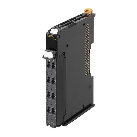
3 Part Names and Functions Indicators There is an indicator that shows the current operating status of the Analog Input Unit or Analog Output Unit. The indicator is shown below. 12 mm width Let- Name Function Model number indications The model numbers of the NX Unit are displayed. (Example) "AD2603"... -
Page 63: Ts Indicator
3 Part Names and Functions 3-2-1 TS Indicator This indicator shows the current status of the Analog Input Unit or Analog Output Unit and its communication status with the CPU Unit or Communications Coupler Unit. The meanings of light statuses are described as follows: Color Status Description... - Page 64 3 Part Names and Functions 3 - 8 NX-series Analog I/O Units User’s Manual for Analog Input Units and Analog Output Units (W522)
-
Page 65: Installation And Wiring
Installation and Wiring This section describes how to install the NX Units, the types of power supplies provided to the NX Units and wiring methods, and how to wire the NX Units. 4-1 Installing NX Units ..........4-2 4-1-1 Installing NX Units . -
Page 66: Installing Nx Units
4 Installation and Wiring Installing NX Units This section describes how to install NX Units. Refer to the user's manual for the CPU Unit or Communications Coupler Unit to which NX Units are connected for information on preparations of installation and installation in a control panel. 4-1-1 Installing NX Units This section describes how to mount two NX Units to each other. - Page 67 4 Installation and Wiring Precautions for Correct Use • When you install an NX Unit, do not touch or bump the pins in the NX bus connector. • When you handle an NX Unit, be careful not to apply any stress to the pins in the NX bus connector.
-
Page 68: Attaching Markers
Attaching Markers Markers can be attached to the NX Units and terminal blocks on NX Units to identify them. The plastic markers made by OMRON are installed for the factory setting. The ID information can be written on them. Commercially available markers can also be installed. - Page 69 Special marker printer UM EN BLUEMARK X1 PrintJet PRO The markers made by OMRON cannot be printed on with commercially available special printers. 4 - 5 NX-series Analog I/O Units User’s Manual for Analog Input Units and Analog Output Units (W522)
-
Page 70: Removing Nx Units
4 Installation and Wiring 4-1-3 Removing NX Units Precautions for Safe Use Always turn OFF the Unit power supply and I/O power supply before you remove the NX Unit. Use a flat-blade screwdriver to pull up the DIN Track mounting hook on the Unit to remove. Flat-blade screwdriver DIN track mounting hook Put your fingers on the protrusions for removing multiple NX Units including the Unit to be... -
Page 71: Installation Orientation
4 Installation and Wiring Precautions for Correct Use • When removing an NX Unit, remove multiple Units together which include the one you want to remove. If you attempt to remove only one Unit, it is stuck and hard to pull out. •... - Page 72 4 Installation and Wiring Installation Orientation in the Case of a Slave Terminal Orientation is possible in the following six directions. (A) is the upright orientation and (B) to (F) are other orientations. Upper Lower However, there are restrictions on the installation orientation and restrictions to the specifications that can result from the Communications Coupler Units and NX Units that are used.
-
Page 73: Power Supply Types And Wiring
4 Installation and Wiring Power Supply Types and Wiring There are the following two types of power supplies that supply power to the NX Units. Power supply Description name NX Unit power This power supply is used for operating the NX Units. supply I/O power supply This power supply is used for driving the I/O circuits of the NX Units and for the connected... - Page 74 Units. For a complete list of the latest power supply Units in the NX Series, refer to the product catalog or OMRON websites, or contact your OMRON representatives. 4 - 10 NX-series Analog I/O Units User’s Manual for Analog Input Units and Analog Output Units (W522)
-
Page 75: Calculating The Total Current Consumption From I/O Power Supply
4 Installation and Wiring 4-2-2 Calculating the Total Current Consumption from I/O Power Sup- The total current consumption of I/O power supplied from the NX bus must be within the range of the maximum I/O power supply current of the Communications Coupler Unit or the Additional I/O Power Supply Unit. -
Page 76: Wiring The Terminals
4 Installation and Wiring Wiring the Terminals This section describes how to wire the terminals on the Analog Input Units and Analog Output Units. WARNING Make sure that the voltages and currents that are input to the Units and slaves are within the speci- fied ranges. - Page 77 4 Installation and Wiring Applicable Wires The wires that you can connect to the screwless clamping terminal block are twisted wires, solid wires, and ferrules that are attached to the twisted wires. The following section describes the dimensions and processed methods for applicable wires. Dimensions of Wires Connected to the Terminal Block The dimensions of wires that you can connect into the terminal holes of the screwless clamping ter- minal block are as in the figure below.
- Page 78 4 Installation and Wiring Using Ferrules If you use ferrules, attach the twisted wires to them. Observe the application instructions for your ferrules for the wire stripping length when attaching fer- rules. Always use plated one-pin ferrules. Do not use unplated ferrules or two-pin ferrules. The applicable ferrules, wires, and crimping tools are listed in the following table.
- Page 79 4 Installation and Wiring Using Twisted Wires/Solid Wires If you use twisted wires or solid wires, use the following table to determine the correct wire specifica- tions. Terminals Wire type Conductor Classifica- Current Twisted wires Solid wire Wire size length (strip- ping length) tion capacity...
- Page 80 4 Installation and Wiring Connecting/Removing Wires This section describes how to connect and remove wires. Terminal Block Parts and Names Release hole Terminal hole Required Tools Use a flat-blade screwdriver to connect and remove wires. Use the following flat-blade screwdriver. Side view Front view 8 to 12°...
- Page 81 4 Installation and Wiring Connecting Ferrules Insert the ferrule straight into the terminal hole. It is not necessary to press a flat-blade screwdriver into the release hole. Ferrule After you make a connection, make sure that the ferrule is securely connected to the terminal block. Connecting Twisted Wires/Solid Wires Use the following procedure to connect the twisted wires or solid wires to the terminal block.
- Page 82 4 Installation and Wiring Leave the flat-blade screwdriver pressed into the release hole and insert the twisted wire or the solid wire into the terminal hole. Insert the twisted wire or the solid wire until the stripped portion is no longer visible to prevent shorting.
- Page 83 4 Installation and Wiring Precautions for Safe Use • Do not press the flat-blade screwdriver straight into the release hole. Doing so may break the terminal block. • When you insert a flat-blade screwdriver into a release hole, press it down with a force of 30 N max.
- Page 84 4 Installation and Wiring Securing Wires It is necessary to secure wires to the screwless clamping terminal block depending on the wire types that are used or the current flows on the wires. The following table gives the necessity for securing wires. Wire type Terminals Twisted wires...
- Page 85 4 Installation and Wiring Bundle the wires with a cable tie and secure them to the screwless clamping terminal block. Secure wires within the range of 30 mm from the screwless clamping terminal block. 30 mm 4 - 21 NX-series Analog I/O Units User’s Manual for Analog Input Units and Analog Output Units (W522)
- Page 86 4 Installation and Wiring Removing Wires Use the following procedure to remove the wires from the terminal block. The removal method is the same for ferrules, twisted wires, and solid wires. If wires are secured firmly to the terminal block, release them first Press the flat-blade screwdriver diagonally into the release hole.
- Page 87 4 Installation and Wiring Precautions for Safe Use • Do not press the flat-blade screwdriver straight into the release hole. Doing so may break the terminal block. • When you insert a flat-blade screwdriver into a release hole, press it down with a force of 30 N max.
- Page 88 4 Installation and Wiring Removing a Terminal Block Press the lock lever on the terminal block and pull out the top of the terminal block to remove it. Lock lever Terminal block Attaching a Terminal Block Mount the terminal block hook on the guide at the bottom of the NX Unit, lift up the terminal block, and press in on the top of the terminal block until you hear it engage.
- Page 89 4 Installation and Wiring Preventing Incorrect Attachment of Terminal Blocks In order to prevent unintentionally installing the wrong terminal block, you can limit the combination of a Unit and a terminal block. Insert three Coding Pins (NX-AUX02) into three of the six incorrect attachment prevention holes on the Unit and on the terminal block.
- Page 90 1 through 6 in the figure below. As shown in the following table, there are 20 unique pin patterns that can be used. Terminal block Unit Holes used by Holes used by OMRON OMRON Holes for incorrect Holes for incorrect attachment prevention attachment prevention...
- Page 91 Precautions for Correct Use • OMRON uses the holes other than No. 1 to 6 in the figure on the previous page. If you insert a Coding Pin into one of the holes used by OMRON on the terminal block side, this makes it impossible to mount the terminal block on a Unit.
-
Page 92: Checking The Wiring
4 Installation and Wiring Unit 4-3-2 Checking the Wiring Check the wiring by reading input data or writing output data from Slave Terminals using the Watch Tab Page of the Support Software. For Input Units, you can turn ON/OFF the inputs from external devices that are connected to the target Units and monitor the results. -
Page 93: Wiring Examples
4 Installation and Wiring Wiring Examples This section gives wiring examples for the Analog Input Units and Analog Output Units and precautions for wiring. 4-4-1 Wiring the Analog Input Units Wiring Example 1 (Input method: Single-ended input) Additional I/O Voltage Input Unit Power Supply Unit NX-AD3603 NX-PF0630... - Page 94 4 Installation and Wiring It is not necessary to connect the shield normally. However, if noise affects the Unit, ground the end of the shield on the Input Unit side. In this case, do not connect the end of the shield anywhere on output device.
-
Page 95: Wiring The Analog Output Units
4 Installation and Wiring 4-4-2 Wiring the Analog Output Units Additional I/O Voltage Output Unit Power Supply Unit NX-DA3603 NX-PF0630 Voltage output + Voltage output − 24 VDC Precautions for Correct Use To ensure this NX Unit is kept in the best operating condition, observe the following points when wiring to avoid the effects of the noise. -
Page 96: Precautions When Using Common Power Supply For Input Devices Of Analog Input Units
4 Installation and Wiring 4-4-3 Precautions when Using Common Power Supply for Input Devices of Analog Input Units If you use Analog Input Units that take differential input, when more than one input device is using the same power supply, and voltage input is being supplied, a disconnection will occur as follows. Analog Input Unit Input n+ Power... -
Page 97: I/O Refreshing
I/O Refreshing This section describes the types and functions of I/O refreshing for the NX Units. 5-1 I/O Refreshing ..........5-2 5-1-1 I/O Refreshing from CPU Units to NX Units . -
Page 98: I/O Refreshing From Cpu Units To Nx Units
5 I/O Refreshing I/O Refreshing This section describes I/O refreshing for NX Units. 5-1-1 I/O Refreshing from CPU Units to NX Units An NX-series NX1P2 CPU Unit cyclically performs I/O refreshing with the NX Units. The following period and two cycles affect operation of the I/O refreshing between the CPU Unit and the NX Units. -
Page 99: I/O Refreshing From Cpu Units Or Industrial Pcs To Slave Terminal
5 I/O Refreshing 5-1-2 I/O Refreshing from CPU Units or Industrial PCs to Slave Termi- The CPU Unit or Industrial PC cyclically performs I/O refreshing with the Slave Terminal through the Communications Master and Communications Coupler Units. The following four cycles affect operation of the I/O refreshing between the NX Unit on a Slave Terminal and the CPU Unit or Industrial PC. - Page 100 5 I/O Refreshing Operation of I/O Refreshing with NX-series CPU Units The following shows the operation of I/O refreshing when the built-in EtherCAT port on the NX-series CPU Unit is used for communications with an EtherCAT Slave Terminal. • The process data communications cycle in item (b) and the refresh cycle of the NX bus in item (c) are automatically synchronized with the primary period or the task period of the priority-5 periodic task of the CPU Unit in item (a).
-
Page 101: I/O Refreshing Methods
5 I/O Refreshing I/O Refreshing Methods This section describes I/O refreshing methods for the NX Units. 5-2-1 Types of I/O Refreshing Methods Methods of I/O Refreshing between the CPU Unit and NX Units The I/O refreshing methods that you can use between the CPU Unit and the NX Units depend on the connected CPU Unit. - Page 102 5 I/O Refreshing Methods of I/O Refreshing between the Communications Coupler Unit and NX Units The I/O refreshing methods that you can use between the Communications Coupler Unit and the NX Units depend on the Communications Coupler Unit that is used. Refer to the user’s manual for the connected Communications Coupler Unit for information on the I/O refreshing methods that you can use between the Communications Coupler Unit and the NX Units.
-
Page 103: Setting The I/O Refreshing Methods
5 I/O Refreshing 5-2-2 Setting the I/O Refreshing Methods Setting Methods between the CPU Unit and the NX Units How to set an I/O refreshing method between the CPU Unit and the NX Units is determined by the con- nected CPU Unit. Refer to the software user’s manual for the connected CPU Unit for information on how to set an I/O refreshing method between the CPU Unit and the NX Units. -
Page 104: Selecting Nx Units
5 I/O Refreshing *1. Two types of time stamp refreshing are available: one is input refreshing with input changed time and the other is output refreshing with specified time stamp. *2. The EtherCAT Slave Terminal operates in DC Mode. *3. The EtherCAT Slave Terminal operates in Free-Run Mode. *4. - Page 105 5 I/O Refreshing Inputs • The Analog Input Units repeatedly perform AD conversion in the order of inputs for which the used channels are set to enable. AD conversion is not synchronized with I/O refreshing of the NX bus. • At the time of I/O refreshing, the CPU Unit reads the converted values from the NX Unit for one Unit that AD conversion is complete before the timing to read inputs.
- Page 106 5 I/O Refreshing Description of Slave Terminal Operation • The Communications Coupler Unit performs I/O refreshing for NX Units. (Refer to (a) in the figure below.) • The NX Units read inputs or refresh outputs at the time of I/O refreshing. (Refer to (b) in the figure below.) •...
- Page 107 5 I/O Refreshing Outputs • The Analog Output Units repeatedly perform DA conversion in the order of outputs for which the used channels are set to enable. The outputs are refreshed once per DA conversion cycle for one Unit when DA conversion of the last output is complete. The refreshing is not synchronized with I/O refreshing of the NX bus.
-
Page 108: Synchronous Input Refreshing
5 I/O Refreshing 5-2-5 Synchronous Input Refreshing The I/O refreshing method described below. Among Slave Terminals, only EtherCAT Slave Terminals support this refreshing method. • The timing to read inputs is synchronized on a fixed interval between more than one NX Unit con- nected to a CPU Unit. - Page 109 5 I/O Refreshing I/O refreshing synchronization (c) Interval of I/O refreshing The longest AD conversion time is not constant. is within one cycle. (d) Interval of synchronization (b) The CPU Unit reads the timing is constant. data that is read by the Unit at I/O refreshing.
- Page 110 5 I/O Refreshing Slave Terminal Operation The following describes the operation of synchronous input refreshing of an EtherCAT Slave Termi- nal connected to the built-in EtherCAT port. • All Digital Input Units and Analog Input Units that operate with synchronous input refreshing in the Slave Terminal read their inputs at the same time at a fixed interval based on Sync0.
- Page 111 5 I/O Refreshing I/O refreshing synchronization (c) Interval of I/O refreshing The longest AD conversion time is not constant. is within one cycle. (b) The Communications Coupler Unit (d) Interval of Sync0 is constant. reads the data that is read by the Unit at I/O refreshing.
-
Page 112: Synchronous Output Refreshing
5 I/O Refreshing 5-2-6 Synchronous Output Refreshing The I/O refreshing method described below. Among Slave Terminals, this refreshing method is supported only by EtherCAT Slave Terminals. • The timing to refresh outputs is synchronized on a fixed interval between more than one NX Unit con- nected to a CPU Unit. - Page 113 5 I/O Refreshing Offset between synchronization timing and timing to refresh outputs This time is automatically calculated by the Sysmac Studio. (b)The Communication Coupler Unit refreshes I/O refreshing synchronization the output values at I/O refreshing. The longest DA conversion time is within one cycle.
- Page 114 5 I/O Refreshing Slave Terminal Operation The following describes the operation of synchronous output refreshing of an EtherCAT Slave Ter- minal connected to the built-in EtherCAT port. • All Digital Output Units and Analog Output Units that operate with synchronous output refreshing in the Slave Terminal refresh their outputs at the same time at a fixed interval based on Sync0.
- Page 115 5 I/O Refreshing Settings Same as the settings for synchronous input refreshing. Refer to Settings in 5-2-5 Synchronous Input Refreshing on page 5-12 for details. 5 - 19 NX-series Analog I/O Units User’s Manual for Analog Input Units and Analog Output Units (W522)
- Page 116 5 I/O Refreshing 5 - 20 NX-series Analog I/O Units User’s Manual for Analog Input Units and Analog Output Units (W522)
- Page 117 Analog Input Units This section describes the types and functions of Analog Input Units. 6-1 Types of Analog Input Units ........6-2 6-2 Input Range and Converted Values .
-
Page 118: Types Of Analog Input Units
6 Analog Input Units Types of Analog Input Units Analog Input Units are the NX Units with functionality to convert analog input signals such as -10 to +10 V and 4 to 20 mA to digital values. The Analog Input Unit types are described below. Analog Input Units (Screwless Clamping Terminal Block, 12 mm Width) Resolu-... - Page 119 6 Analog Input Units Resolu- Input I/O refresh- Conver- Model Input range Reference tion method ing method sion time point Sin- NX-AD4203 gle-ende P. A-18 Free-Run 1/8000 250 μs/point refreshing NX-AD4204 P. A-19 4 to 20 mA Switching Differen- Synchronous tial NX-AD4208 1/30000...
-
Page 120: Input Range And Converted Values
6 Analog Input Units Input Range and Converted Values Input analog signals are converted to digital values according to the input range shown below. If the input range exceeds the value range for which conversion is possible, the converted value is fixed at the upper or lower limit. - Page 121 6 Analog Input Units Input Range: 4 to 20 mA 1/8000 Resolution A current of 4 to 20 mA is converted to a signed integer value (0 to 8000). The input current range for which conversion is possible is 3.2 to 20.8 mA and here the converted value is a signed integer value (-400 to +8400).
-
Page 122: Specifications Of I/O Data
6 Analog Input Units Specifications of I/O Data This section describes the I/O data for the Analog Input Units. 6-3-1 Allocable I/O Data This section describes the allocable I/O data in the Analog Input Unit. An I/O entry mapping is assigned to the I/O allocation settings for the Analog Input Unit. A specific I/O entry is assigned to the I/O entry mapping for each NX Unit model. - Page 123 6 Analog Input Units Eight-point Input Units Data Default I/O port Subin- Data name Description Index type value name Ch1 Analog Input Value of analog input 1 Ch1 Analog 6000 hex 01 hex Value Input Value Ch2 Analog Input Value of analog input 2 Ch2 Analog 02 hex Value...
-
Page 124: List Of Settings
6 Analog Input Units List of Settings The followings are the setting descriptions, setting ranges, and default values of the functions that can be used in the Analog Input Units. The settings are reflected after the Unit is restarted. Precautions for Safe Use The Unit is required to restart after the transfer of Unit operation settings on the Support Soft- ware is completed. - Page 125 6 Analog Input Units *2. The setting range of Ch Input Moving Average Time depends on the model. The setting range for each model is as follows. NX Units Setting range NX-AD2203/AD2204/AD2603/AD2604 0 to 32000 NX-AD2208/AD2608 0 to 640 Four-point Input Units Default Setting Subin-...
- Page 126 6 Analog Input Units Eight-point Input Units Default Setting Subin- Refer- Setting name Description Unit Index value range ence Ch1 Enable/Disable Set to enable or disable TRUE TRUE or 5002 01 hex P. 6-13 the channel. FALSE Ch2 Enable/Disable TRUE TRUE or 02 hex FALSE: Disable...
- Page 127 6 Analog Input Units *2. The setting range of Ch Input Moving Average Time depends on the model. The setting range for each model is as follows. NX Units Setting range NX-AD4203/AD4204/AD4603/AD4604 0 to 32000 NX-AD4208/4608 0 to 640 6 - 11 NX-series Analog I/O Units User’s Manual for Analog Input Units and Analog Output Units (W522)
-
Page 128: Function
6 Analog Input Units Function This section describes the Analog Input Unit functions. Refer to the specifications of each model in A-1 Data Sheet on page A-2 for details on the functions. 6-5-1 List of Analog Input Unit Functions Function name Description Reference Free-Run Refreshing... -
Page 129: Selecting Channel To Use
6 Analog Input Units 6-5-2 Selecting Channel To Use Purpose This function skips the conversion processing and error detection processing for unused inputs, and shortens the conversion time. Details on the Function Normally in this Unit, the input signals for the number of input points are converted in sequence. The setting can be changed, so that unused inputs are not converted. - Page 130 6 Analog Input Units Eight-point Input Units Default Setting name Description Unit value Ch1 Enable/Disable Set to enable or disable the channel. TRUE Ch2 Enable/Disable TRUE FALSE: Disable Ch3 Enable/Disable TRUE TRUE: Enable Ch4 Enable/Disable TRUE Ch5 Enable/Disable TRUE Ch6 Enable/Disable TRUE Ch7 Enable/Disable TRUE...
- Page 131 6 Analog Input Units Additional Information • Click a list button on the tab page to display the item in the Edit Unit Operation Settings Tab Page. Example: Select Input Enable/Disable Setting Only Input Enable/Disable Setting under under Ch1 Ch1 is displayed •...
- Page 132 6 Analog Input Units Calculating Conversion Time The conversion time per unit according to the number of available conversion channels is as follows. Conversion time per unit (μs) Number of available Conversion time: Conversion time: conversion channels 250 μs/point 10 μs/point 1 channel 2 channels 3 channels...
-
Page 133: Moving Average
6 Analog Input Units 6-5-3 Moving Average Purpose This function averages the inputs if they fluctuate minutely due to noise and so on as shown in the fig- ure below, and obtains smooth input values. Analog input value Actual input Input after averaging processing Time Details on the Function... - Page 134 6 Analog Input Units Analog conversion time (number of channels used × 250 μs or 10μs ) Actual analog conversion data Time Moving average Initial Initial Initial Initial Converted value = (D1×4) /4 data data data data calculation (Initial) Moving average Initial Initial Initial...
- Page 135 6 Analog Input Units Two-point Input Units Default Setting Setting name Description Unit value range Ch1 Input Moving Aver- Set the time to process moving average. μs age Time Ch2 Input Moving Aver- μs age Time *1. The setting range of Ch Input Moving Average Time depends on the model.
- Page 136 6 Analog Input Units Eight-point Input Units Default Setting Setting name Description Unit value range Ch1 Input Moving Aver- Set the time to process moving average. μs age Time Ch2 Input Moving Aver- μs age Time Ch3 Input Moving Aver- μs age Time Ch4 Input Moving Aver-...
- Page 137 6 Analog Input Units Setting Method This section describes how to configure settings with the Sysmac Studio. When you are using Support Software other than the Sysmac Studio, in the Edit Unit Operation Set- tings Tab Page, set the parameters described in the procedure and transfer the settings to the target NX Unit.
- Page 138 6 Analog Input Units Additional Information • Click a list button on the tab page to display the item in the Edit Unit Operation Settings Tab Page. Example: Select Input Moving Average Time Only Input Moving Average Time under under Ch1 Ch1 is displayed •...
-
Page 139: Input Disconnection Detection
6 Analog Input Units 6-5-4 Input Disconnection Detection Purpose This function detects disconnections of the analog input signal lines. However, it is only available when the input range is 4 to 20 mA. Details on the Function • If any analog input signal line (current inputs) of the inputs that are enabled by the selecting channel to use function is disconnected, or the input current is less than 1.2 mA, the converted value is 32767. -
Page 140: Over Range/Under Range Detection
6 Analog Input Units 6-5-5 Over Range/Under Range Detection Purpose This function detects when the input signal exceeds the range for which conversion is possible. Details on the Function • If the input signal exceeds the upper limit of the conversion range, the converted value is fixed at the upper limit. -
Page 141: User Calibration
6 Analog Input Units 6-5-6 User Calibration Purpose This function corrects offsets in the converted values that occur due to the deterioration of the NX Units and calibrate the Units again. You can use this function to calibrate the equipment that requires the periodic calibration. Details on the Function This function corrects the converted values of input voltages and input currents at 2 points, 0% and 100%, as shown in the figure below. - Page 142 6 Analog Input Units Correctable Range The correctable range is -5 to 5% of the input full scale. The correctable range for each input range is as follows. Correctable range Input range 100% -10 to +10 V -11 to -9.0 V 9.0 to 11 V 4 to 20 mA 3.2 to 4.8 mA...
- Page 143 6 Analog Input Units Select the channel you want to calibrate from Channel. Enter the voltage or current corresponding to upper limit (100%) to the Unit terminal, then click the Write Button under Upper limit settings. Click the Yes Button on the confirmation message. 6 - 27 NX-series Analog I/O Units User’s Manual for Analog Input Units and Analog Output Units (W522)
- Page 144 6 Analog Input Units When the writing is completed successfully, the following message is displayed. Click the OK Button. Enter the voltage or current corresponding to lower limit (0%) to the Unit terminal, then click the Write Button under Lower limit settings. Click the Yes Button on the confirmation message.
- Page 145 6 Analog Input Units Additional Information • A new calibration value is reflected immediately after you write it. • When you write a calibration value, if the voltage or current that is input to the Unit terminal is outside the correctable range, the following message will be displayed and calibration will fail.
- Page 146 6 Analog Input Units Reset the Calibration Value to the Default You can reset the calibration value to the default. Right-click the NX Unit, then select User Calibration from the menu. Click the Clear All Button under All Channel Settings. 6 - 30 NX-series Analog I/O Units User’s Manual for Analog Input Units and Analog Output Units (W522)
- Page 147 6 Analog Input Units Click the Yes Button on the confirmation message. When the writing is completed successfully, the following message is displayed. Click the OK Button. 6 - 31 NX-series Analog I/O Units User’s Manual for Analog Input Units and Analog Output Units (W522)
- Page 148 6 Analog Input Units 6 - 32 NX-series Analog I/O Units User’s Manual for Analog Input Units and Analog Output Units (W522)
- Page 149 Analog Output Units This section describes the types and functions of Analog Output Units. 7-1 Types of Analog Output Units ........7-2 7-2 Output Range and Output Set Values .
-
Page 150: Types Of Analog Output Units
7 Analog Output Units Types of Analog Output Units Analog Output Units are the NX Units with functionality to convert output set values set by the user pro- gram to analog signals such as -10 to 10 V and 4 to 20 mA. The Analog Output Unit types are described below. -
Page 151: Output Range And Output Set Values
7 Analog Output Units Output Range and Output Set Values Output set values set by the user program are converted to analog signals according to the output range shown below. If the output set value exceeds the value range for which conversion is possible, the analog value is fixed at the upper or lower limit. - Page 152 7 Analog Output Units Output Range: 4 to 20 mA 1/8000 Resolution The output set value of the signed integer value (0 to 8000) is converted to currents from 4 to 20 mA and output. The output set value range for which conversion is possible is the signed integer (-400 to +8400) and for this case the output voltage becomes from 3.2 to 20.8 mA.
-
Page 153: Specifications Of I/O Data
7 Analog Output Units Specifications of I/O Data This section describes the I/O data for the Analog Output Units. 7-3-1 Allocable I/O Data This section describes the allocable I/O data in the Analog Output Unit. An I/O entry mapping is assigned to the I/O allocation settings for the Analog Output Unit. A specific I/O entry is assigned to the I/O entry mapping for each NX Unit model. -
Page 154: List Of Settings
7 Analog Output Units List of Settings The followings are the setting descriptions, setting ranges, and default values of the functions that can be used in the Analog Output Units. The settings are reflected after the Unit is restarted. Precautions for Safe Use The Unit is required to restart after the transfer of Unit operation settings on the Support Soft- ware is completed. - Page 155 7 Analog Output Units *2. The descriptions of Ch Hold Value Setting are as follows. Set value Setting description Hold Last State Low Limit High Limit User Count Zero Count Four-point Output Units Default Setting Subin- Refer- Setting name Description Unit Index value...
- Page 156 7 Analog Output Units *1. The default value and setting range of Ch Range Setting depend on the model. The default value and set- ting range for each NX Unit are as follows. NX Units Default value Setting range NX-DA3203/DA3205 NX-DA3603/DA3605 *2.
-
Page 157: Functions
7 Analog Output Units Functions This section describes the Analog Output Unit functions. Refer to the specifications of each model in A-1 Data Sheet on page A-2, for details on the functions. 7-5-1 List of Analog Output Unit Functions Function name Description Reference Free-Run Refreshing... -
Page 158: Selecting Channel To Use
7 Analog Output Units 7-5-2 Selecting Channel To Use Purpose This function skips the conversion processing and error detection processing for unused outputs, and shortens the conversion time. Details on the Function Normally in this Unit, the output set values for the number of input points mounted are converted in sequence. - Page 159 7 Analog Output Units Setting Method This section describes how to configure settings with the Sysmac Studio. When you are using Support Software other than the Sysmac Studio, in the Edit Unit Operation Set- tings Tab Page, set the parameters described in the procedure and transfer the settings to the target NX Unit.
- Page 160 7 Analog Output Units Additional Information • Click a list button on the tab page to display the item in the Edit Unit Operation Settings Tab Page. Example: Select Output Enable/Disable Setting Only Output Enable/Disable Setting under under Ch1 Ch1 is displayed •...
- Page 161 7 Analog Output Units Calculating Conversion Time The conversion time per Unit according to the number of available conversion channels is as follows. Conversion time per unit (μs) Number of available Conversion time: Conversion time: conversion channels 250 μs/point 10 μs/point 1 channel 2 channels 3 channels...
-
Page 162: Load Rejection Output Setting
7 Analog Output Units 7-5-3 Load Rejection Output Setting Purpose This function maintains a safe output status by performing the preset output operations when the Analog Output Unit connected to the CPU Unit cannot receive output data from the CPU Unit due to an NX bus error or CPU Unit watchdog timer error In Slave Terminals, this function sets the value to be output when Analog Output Units cannot receive the output set value from the Communications Coupler Unit due to a host error on the Communications... - Page 163 7 Analog Output Units Four-point Output Units Default Setting name Description Unit value Ch1 Hold Value Setting Set the value to output at load OFF. Ch1 User-specified Value Set the value to output when the Load OFF Out- Setting put Setting is set to output the user specified value.
- Page 164 7 Analog Output Units Setting Method This section describes how to configure settings with the Sysmac Studio. When you are using Support Software other than the Sysmac Studio, in the Edit Unit Operation Set- tings Tab Page, set the parameters described in the procedure and transfer the settings to the target NX Unit.
- Page 165 7 Analog Output Units Additional Information • Click a list button on the tab page to display the item in the Edit Unit Operation Settings Tab Page. Example: Select Load Rejection Output Setting Only Load Rejection Output Setting under under Ch1 Ch1 is displayed •...
- Page 166 7 Analog Output Units Click the Transfer to Unit Button. The settings are transferred from the Sysmac Studio to the NX Unit. The settings are reflected after the Unit is restarted. Precautions for Safe Use The Unit is required to restart after the transfer of Unit operation settings on the Support Soft- ware is completed.
-
Page 167: Over Range/Under Range Detection
7 Analog Output Units 7-5-4 Over Range/Under Range Detection Purpose This function detects when the output set value exceeds the range for which conversion is possible. Details on the Function • If the output set value exceeds the upper limit of the conversion range, the converted value is fixed at the upper limit. -
Page 168: User Calibration
7 Analog Output Units 7-5-5 User Calibration Purpose This function corrects offsets in the output voltages and output currents that occur due to the deteriora- tion of the NX Units and calibrate the Units again. You can use this function to calibrate the equipment that requires the periodic calibration. Details on the Function This function corrects the converted values of output voltages and output currents at 2 points, 0% and 100%, as shown in the figure below. - Page 169 7 Analog Output Units Correctable Range The correctable range is -5 to +5% of the output full scale. The correctable range for each output range is as follows. Correctable range Output range 100% -10 to +10 V -11 to -9.0 V 9.0 to 11 V 4 to 20 mA 3.2 to 4.8 mA...
- Page 170 7 Analog Output Units Select the channel you want to calibrate from Channel. Set the minimum value (0%) of Output Unit as the output set value for the channel you want to calibrate. Change the value of Calibration Range under Lower limit settings to calibrate the value of an analog signal that is output from the terminal.
- Page 171 7 Analog Output Units Click the Test Button to output the value of an analog signal that was calibrated in Procedure 4. Make the calibration to correctly output the value of 0% analog signal from the terminal. After you complete the calibration, click the Write Button under Lower limit settings. 7 - 23 NX-series Analog I/O Units User’s Manual for Analog Input Units and Analog Output Units (W522)
- Page 172 7 Analog Output Units Click the Yes Button on the confirmation message. When the writing is completed successfully, the following message is displayed. Click the OK Button. Set the maximum value (100%) of Output Unit as the output set value for the channel you want to calibrate.
- Page 173 7 Analog Output Units Click the Test Button to output the value of an analog signal that was calibrated in Procedure 9. Make the calibration to correctly output the value of 100% analog signal from the terminal. After you complete the calibration, click the Write Button under Upper limit settings. 7 - 25 NX-series Analog I/O Units User’s Manual for Analog Input Units and Analog Output Units (W522)
- Page 174 7 Analog Output Units Click the Yes Button on the confirmation message. When the writing is completed successfully, the following message is displayed. Click the OK Button. Additional Information For the upper limit calibration value and lower limit calibration value, you cannot write the cali- bration value on the Unit if only click the Test Button.
- Page 175 7 Analog Output Units Reset the Calibration Value to the Default You can reset the calibration value to the default. Right-click the NX Unit, then select User Calibration from the menu. 7 - 27 NX-series Analog I/O Units User’s Manual for Analog Input Units and Analog Output Units (W522)
- Page 176 7 Analog Output Units Click the Clear All Button under All Channel Settings. Click the Yes Button on the confirmation message. When the writing is completed successfully, the following message is displayed. Click the OK Button. 7 - 28 NX-series Analog I/O Units User’s Manual for Analog Input Units and Analog Output Units (W522)
-
Page 177: Troubleshooting
Troubleshooting This section provides error information and corrections for errors that can occur when the Analog Input Units and Analog Output Units are used. 8-1 How to Check for Errors ........8-2 8-2 Checking for Errors with the Indicators . -
Page 178: How To Check For Errors
8 Troubleshooting How to Check for Errors Use one of the following error checking methods. • Checking the indicators • Troubleshooting with the Support Software Refer to the user's manual for the CPU Unit or Communications Coupler Unit that the NX Units are connected to for information on checking errors with the troubleshooting functions of the Support Software. -
Page 179: Checking For Errors With The Indicators
8 Troubleshooting Checking for Errors with the Indicators You can use the TS indicators on the NX Units to check the NX Unit status and level of errors. This section describes the meanings of errors that the TS indicator shows and the troubleshooting pro- cedures for them. - Page 180 8 Troubleshooting TS indicator Cause Correction Green Not Lit Control Parameter Error in Mas- Refer to Event Control Parameter Error in Mas- ter on page 8-16. Not Lit Unit Calibration Value Parity Error Refer to Event Unit Calibration Value Parity Error on page 8-17.
-
Page 181: Checking For Errors And Troubleshooting On The Support Software
8 Troubleshooting Checking for Errors and Trouble- shooting on the Support Software Error management on the NX Series is based on the methods used for the NJ/NX/NY-series Control- lers. This allows you to use the Support Software to check the meanings of errors and troubleshooting pro- cedures. -
Page 182: Checking For Errors From Support Software Other Than The Sysmac Studio
8 Troubleshooting Log of Past Errors Open the Sysmac Studio's Controller Event Log Tab Page to check the times, levels, sources, source details, event names, event codes, details, attached information 1 to 4, and corrections for previous errors. Additional Information Number of Logs of Past Errors Event logs in the Analog I/O Units are stored in the CPU Unit or Communications Coupler Unit to which they are connected. -
Page 183: Event Codes And Corrections For Errors
8 Troubleshooting 8-3-3 Event Codes and Corrections for Errors The errors (i.e.,events) that occur in the Analog Input Units and Analog Output Units are given below. The following abbreviations are used in the event level column. Abbreviation Name Major fault level Partial fault level Minor fault level Observation... - Page 184 8 Troubleshooting Level Event code Event name Meaning Assumed cause Reference Obs Info 14C0 0000 hex Unit Calibra- An error occurred in • An error was detected in the P. 8-17 tion Value the user calibration calibration data. Parity Error data in the NX Unit.
- Page 185 8 Troubleshooting Level Event code Event name Meaning Assumed cause Reference Obs Info 80200000 hex NX Unit I/O An I/O communica- For the NX bus of CPU Units P. 8-22 Communica- tions error occurred • An error that prevents normal tions Error in an NX Unit.
- Page 186 8 Troubleshooting Level Event code Event name Meaning Assumed cause Reference Obs Info 80240 000 hex NX Unit A time information For the NX bus of CPU Units P. 8-25 Clock Not error occurred in an • There is a hardware error in an Synchro- NX Unit.
- Page 187 8 Troubleshooting Level Event code Event name Meaning Assumed cause Reference Obs Info 64F5 0000 hex Unit Over The analog input • The analog input data P. 8-28 Range for data for input chan- exceeded the upper limit of the Channel 6 nel 6 exceeded the input range.
- Page 188 8 Troubleshooting Level Event code Event name Meaning Assumed cause Reference Obs Info 64FB 0000 hex Unit Under The analog input • The analog input data went P. 8-31 Range for data for input chan- below the lower limit of the Channel 4 nel 4 went below input range.
-
Page 189: Meaning Of Error
Stops: Execution of the user program stops. Starts: Execution of the user program starts. *5. “System information” indicates internal system information that is used by OMRON. 8 - 13 NX-series Analog I/O Units User’s Manual for Analog Input Units and Analog Output Units (W522) - Page 190 8 Troubleshooting *6. Refer to the appendices of the troubleshooting manual for the connected CPU Unit or Industrial PC for the applicable range of the HMI Troubleshooter. Error Descriptions This section describes the information that occurs on the Analog Input Units and Analog Output Units. Event name Non-volatile Memory Hardware Error Event code...
- Page 191 8 Troubleshooting Event name Analog Unit Calibration Parameter Error Event code 10400000 hex Meaning An error occurred for the calibration data in the Analog Unit. Source Depends on where the Support Source details NX Unit Detection When power is Software is connected and the timing turned ON to system configuration.
- Page 192 8 Troubleshooting Event name Control Parameter Error in Master Event code 10410000 hex Meaning An error occurred in the control parameters that are saved in the master. Source Depends on where the Support Source details NX Unit Detection When power is Software is connected and the timing turned ON to...
- Page 193 8 Troubleshooting Event name Unit Calibration Value Parity Error Event code 14C00000 hex Meaning An error occurred in the user calibration data in the NX Unit. Source Depends on where the Support Source details NX Unit Detection Continuously Software is connected and the timing system configuration.
- Page 194 8 Troubleshooting Event name Unit I/O Disconnection Detected for Channel 2 Event code 65040000 hex Meaning A disconnected input was detected for channel 2. Source Depends on where the Support Source details NX Unit Detection Continuously Software is connected and the timing system configuration.
- Page 195 8 Troubleshooting Event name Unit I/O Disconnection Detected for Channel 4 Event code 65060000 hex Meaning A disconnected input was detected for channel 4. Source Depends on where the Support Source details NX Unit Detection Continuously Software is connected and the timing system configuration.
- Page 196 8 Troubleshooting Event name Unit I/O Disconnection Detected for Channel 6 Event code 65080000 hex Meaning A disconnected input was detected for channel 6. Source Depends on where the Support Source details NX Unit Detection Continuously Software is connected and the timing system configuration.
- Page 197 8 Troubleshooting Event name Unit I/O Disconnection Detected for Channel 8 Event code 650A0000 hex Meaning A disconnected input was detected for channel 8. Source Depends on where the Support Source details NX Unit Detection Continuously Software is connected and the timing system configuration.
- Page 198 8 Troubleshooting Event name NX Unit I/O Communications Error Event code 80200000 hex Meaning An I/O communications error occurred in an NX Unit. Source Depends on where the Support Source details NX Unit Detection Continuously Software is connected and the timing system configuration.
- Page 199 8 Troubleshooting Cause and Assumed cause Correction Prevention correction For the NX bus of CPU Units An error that prevents normal NX Check the error that occurred in Take preventive measures against bus communications occurred in a the CPU Unit and perform the the error that occurred in the CPU required corrections.
- Page 200 8 Troubleshooting Event name NX Unit Output Synchronization Error Event code 80210000 hex Meaning An output synchronization error occurred in the NX Unit. Source Depends on where the Support Source details NX Unit Detection Continuously Software is connected and the timing system configuration.
- Page 201 8 Troubleshooting Event name NX Unit Clock Not Synchronized Error Event code 80240000 hex Meaning A time information error occurred in an NX Unit. Source Depends on where the Support Source details NX Unit Detection Continuously Software is connected and the timing system configuration.
- Page 202 8 Troubleshooting Event name Unit Over Range for Channel 1 Event code 64F0 0000 hex Meaning The analog input data for input channel 1 exceeded the upper limit of the input range. Or, the analog output data for output channel 1 exceeded the upper limit of the output range. Source Depends on where the Support Source details...
- Page 203 8 Troubleshooting Event name Unit Over Range for Channel 3 Event code 64F20000 hex Meaning The analog input data for input channel 3 exceeded the upper limit of the input range. Or, the analog output data for output channel 3 exceeded the upper limit of the output range. Source Depends on where the Support Source details...
- Page 204 8 Troubleshooting Event name Unit Over Range for Channel 5 Event code 64F4 0000 hex Meaning The analog input data for input channel 5 exceeded the upper limit of the input range. Or, the analog output data for output channel 5 exceeded the upper limit of the output range. Source Depends on where the Support Source details...
- Page 205 8 Troubleshooting Event name Unit Over Range for Channel 7 Event code 64F60000 hex Meaning The analog input data for input channel 7 exceeded the upper limit of the input range. Or, the analog output data for output channel 7 exceeded the upper limit of the output range. Source Depends on where the Support Source details...
- Page 206 8 Troubleshooting Event name Unit Under Range for Channel 1 Event code 64F8 0000 hex Meaning The analog input data for input channel 1 went below the lower limit of the input range. Or, the analog output data for output channel 1 went below the lower limit of the output range. Source Depends on where the Support Source details...
- Page 207 8 Troubleshooting Event name Unit Under Range for Channel 3 Event code 64FA0000 hex Meaning The analog input data for input channel 3 went below the lower limit of the input range. Or, the analog output data for output channel 3 went below the lower limit of the output range. Source Depends on where the Support Source details...
- Page 208 8 Troubleshooting Event name Unit Under Range for Channel 5 Event code 64FC 0000 hex Meaning The analog input data for input channel 5 went below the lower limit of the input range. Or, the analog output data for output channel 5 went below the lower limit of the output range. Source Depends on where the Support Source details...
- Page 209 8 Troubleshooting Event name Unit Under Range for Channel 7 Event code 64FE0000 hex Meaning The analog input data for input channel 7 went below the lower limit of the input range. Or, the analog output data for output channel 7 went below the lower limit of the output range. Source Depends on where the Support Source details...
- Page 210 8 Troubleshooting Event name Event Log Cleared Event code 90400000 hex Meaning The event log was cleared. Source Depends on where the Support Source details NX Unit Detection When Software is connected and the timing commanded system configuration. from user Error Level Information...
-
Page 211: Resetting Errors
8 Troubleshooting Resetting Errors Refer to the user's manual for the connected CPU Unit or Communications Coupler Unit for information on how to reset errors. 8 - 35 NX-series Analog I/O Units User’s Manual for Analog Input Units and Analog Output Units (W522) -
Page 212: Troubles Specific To Each Type Of Nx Units
8 Troubleshooting Troubles Specific to Each Type of NX Units 8-5-1 Troubles Common to All Analog Input Units and Analog Output Units Problem Assumed cause Correction The converted values or The user calibration error is Execute the user calibration again. analog signal values are too large. -
Page 213: Analog Output Units
8 Troubleshooting 8-5-3 Analog Output Units Problem Assumed cause Correction The expected output is not The output settings at load Set the output value at load rejection. held when NX bus error or rejection are incorrect. communications errors occur. The user calibration is not Attempted to make calibration Set the voltage/current within the correction range accepted. -
Page 214: Troubleshooting Flowchart
8 Troubleshooting Troubleshooting Flowchart Refer to the user's manual for the connected CPU Unit or Communications Coupler Unit for details on the standard troubleshooting process when an error occurs. 8 - 38 NX-series Analog I/O Units User’s Manual for Analog Input Units and Analog Output Units (W522) -
Page 215: Inspection And Maintenance
Inspection and Maintenance This section describes how to clean, inspect, and maintain the system. 9-1 Cleaning and Inspection ........9-2 9-1-1 Cleaning . -
Page 216: Cleaning And Inspection
9 Inspection and Maintenance Cleaning and Inspection This section describes daily device maintenance such as cleaning and inspection. Make sure to perform daily or periodic inspections in order to maintain the functions of the Analog Input Units and Analog Output Units in the best operating condition. 9-1-1 Cleaning Perform the following cleaning procedures periodically to ensure the Analog Input Units and Analog... - Page 217 9 Inspection and Maintenance Periodic Inspection Items Inspec- Inspection details Criteria Correction tion item External Is the power supply voltage mea- Within the power supply Use a voltage tester to check the power power sup- sured at the terminal block within voltage range supply at the terminals.
- Page 218 9 Inspection and Maintenance Tools Required for Inspections Required Tools • Phillips screwdriver • Flat-blade screwdriver • Voltage tester or digital voltmeter • Industrial alcohol and pure cotton cloth Tools Required Occasionally • Oscilloscope • Thermometer and hygrometer 9 - 4 NX-series Analog I/O Units User’s Manual for Analog Input Units and Analog Output Units (W522)
-
Page 219: Maintenance Procedures
9 Inspection and Maintenance Maintenance Procedures When you replace an Analog Input Unit or Analog Output Unit, follow the procedure in the user's manual for the connected CPU Unit or Communications Coupler Unit. 9 - 5 NX-series Analog I/O Units User’s Manual for Analog Input Units and Analog Output Units (W522) - Page 220 9 Inspection and Maintenance 9 - 6 NX-series Analog I/O Units User’s Manual for Analog Input Units and Analog Output Units (W522)
-
Page 221: Appendices
Appendices The appendices provide the data sheets of the Analog Input Units and Analog Output Units, and the dimensions of the Analog Input Units and Analog Output Units. A-1 Data Sheet ........... . A-2 A-1-1 Model List . -
Page 222: A-1 Data Sheet
Appendices A-1 Data Sheet This section provides the specifications of individual Analog Input Units and Analog Output Units. A-1-1 Model List Analog Input Units (Screwless Clamping Terminal Block, 12 mm Width) Resolu- Input I/O refresh- Conver- Model Input range Reference tion method ing method... - Page 223 Appendices Resolu- Input I/O refresh- Conver- Model Input range Reference tion method ing method sion time poin Sin- NX-AD4203 gle-ende P. A-18 Free-Run 1/8000 250 μs/point refreshing NX-AD4204 P. A-19 4 to 20 mA Switching Differen- Synchronous tial NX-AD4208 1/30000 I/O refreshing 10 μs/point P.
-
Page 224: A-1-2 Analog Input Units
Appendices A-1-2 Analog Input Units Description of Items on Data Sheet of the Analog Input Unit The meanings of the items on the data sheet of the Analog Input Unit are explained in the table below. Item Description Unit name The name of the Unit. - Page 225 Appendices Analog Input Units (Screwless Clamping Terminal Block, 12 mm Width) Unit name Analog Input Unit (current input type) Model NX-AD2203 Number of points 2 points External connection Screwless clamping terminal block (8 ter- terminals minals) I/O refreshing method Free-Run refreshing Indicators TS indicator Input method...
- Page 226 Appendices Terminal connection Additional I/O Current Input Unit diagram Power Supply Unit NX-AD2203 Input1+ Input2+ Input + 24 V (Sensor power supply +) 0 V (Sensor power supply − / Input −) 24 VDC Three-wire sensor The NC terminal is not connected to the internal circuit. Input disconnection Supported detection...
- Page 227 Appendices Unit name Analog Input Unit (current input type) Model NX-AD2204 Number of points 2 points External connection Screwless clamping terminal block (8 ter- terminals minals) I/O refreshing method Free-Run refreshing Indicators TS indicator Input method Differential input Input range 4 to 20 mA Input conversion range -5 to 105% (full-scale)
- Page 228 Appendices Unit name Analog Input Unit (current input type) Model NX-AD2208 Number of points 2 points External connection Screwless clamping terminal block (8 ter- terminals minals) I/O refreshing method Switching synchronous I/O refreshing and Free-Run refreshing Indicators TS indicator Input method Differential input Input range 4 to 20 mA...
- Page 229 Appendices Unit name Analog Input Unit (voltage input type) Model NX-AD2603 Number of points 2 points External connection Screwless clamping terminal block (8 ter- terminals minals) I/O refreshing method Free-Run refreshing Indicators TS indicator Input method Single-ended input Input range -10 to +10 V Input conversion range -5 to 105% (full scale)
- Page 230 Appendices Unit name Analog Input Unit (voltage input type) Model NX-AD2604 Number of points 2 points External connection Screwless clamping terminal block (8 ter- terminals minals) I/O refreshing method Free-Run refreshing Indicators TS indicator Input method Differential input Input range -10 to +10 V Input conversion range -5 to 105% (full scale)
- Page 231 Appendices Unit name Analog Input Unit (voltage input type) Model NX-AD2608 Number of points 2 points External connection Screwless clamping terminal block (8 ter- terminals minals) I/O refreshing method Switching synchronous I/O refreshing and Free-Run refreshing Indicators TS indicator Input method Differential input Input range -10 to +10 V...
- Page 232 Appendices Unit name Analog Input Unit (current input type) Model NX-AD3203 Number of points 4 points External connection Screwless clamping terminal block (12 ter- terminals minals) I/O refreshing method Free-Run refreshing Indicators TS indicator Input method Single-ended input Input range 4 to 20 mA Input conversion range -5 to 105% (full scale)
- Page 233 Appendices Unit name Analog Input Unit (current input type) Model NX-AD3204 Number of points 4 points External connection Screwless clamping terminal block (12 ter- terminals minals) I/O refreshing method Free-Run refreshing Indicators TS indicator Input method Differential input Input range 4 to 20 mA Input conversion range -5 to 105% (full scale)
- Page 234 Appendices Unit name Analog Input Unit (current input type) Model NX-AD3208 Number of points 4 points External connection Screwless clamping terminal block (12 ter- terminals minals) I/O refreshing method Switching synchronous I/O refreshing and Free-Run refreshing Indicators TS indicator Input method Differential input Input range 4 to 20 mA...
- Page 235 Appendices Unit name Analog Input Unit (voltage input type) Model NX-AD3603 Number of points 4 points External connection Screwless clamping terminal block (12 ter- terminals minals) I/O refreshing method Free-Run refreshing Indicators TS indicator Input method Single-ended input Input range -10 to +10 V Input conversion range -5 to 105% (full scale)
- Page 236 Appendices Unit name Analog Input Unit (voltage input type) Model NX-AD3604 Number of points 4 points External connection Screwless clamping terminal block (12 ter- terminals minals) I/O refreshing method Free-Run refreshing Indicators TS indicator Input method Differential input Input range -10 to +10 V Input conversion range -5 to 105% (full scale)
- Page 237 Appendices Unit name Analog Input Unit (voltage input type) Model NX-AD3608 Number of points 4 points External connection Screwless clamping terminal block (12 ter- terminals minals) I/O refreshing method Switching synchronous I/O refreshing and Free-Run refreshing Indicators TS indicator Input method Differential input Input range -10 to +10 V...
- Page 238 Appendices Unit name Analog Input Unit (current input type) Model NX-AD4203 Number of points 8 points External connection Screwless clamping terminal block (16 ter- terminals minals) I/O refreshing method Free-Run refreshing Indicators TS indicator Input method Single-ended input Input range 4 to 20 mA Input conversion range -5 to 105% (full scale)
- Page 239 Appendices Unit name Analog Input Unit (current input type) Model NX-AD4204 Number of points 8 points External connection Screwless clamping terminal block (16 ter- terminals minals) I/O refreshing method Free-Run refreshing Indicators TS indicator Input method Differential input Input range 4 to 20 mA Input conversion range -5 to 105% (full scale)
- Page 240 Appendices Unit name Analog Input Unit (current input type) Model NX-AD4208 Number of points 8 points External connection Screwless clamping terminal block (16 ter- terminals minals) I/O refreshing method Switching synchronous I/O refreshing and Free-Run refreshing Indicators TS indicator Input method Differential input Input range 4 to 20 mA...
- Page 241 Appendices Unit name Analog Input Unit (voltage input type) Model NX-AD4603 Number of points 8 points External connection Screwless clamping terminal block (16 ter- terminals minals) I/O refreshing method Free-Run refreshing Indicators TS indicator Input method Single-ended input Input range -10 to +10 V Input conversion range -5 to 105% (full scale)
- Page 242 Appendices Unit name Analog Input Unit (voltage input type) Model NX-AD4604 Number of points 8 points External connection Screwless clamping terminal block (16 ter- terminals minals) I/O refreshing method Free-Run refreshing Indicators TS indicator Input method Differential input Input range -10 to +10 V Input conversion range -5 to 105% (full scale)
- Page 243 Appendices Unit name Analog Input Unit (voltage input type) Model NX-AD4608 Number of points 8 points External connection Screwless clamping terminal block (16 ter- terminals minals) I/O refreshing method Switching synchronous I/O refreshing and Free-Run refreshing Indicators TS indicator Input method Differential input Input range -10 to +10 V...
-
Page 244: A-1-3 Analog Output Units
Appendices A-1-3 Analog Output Units Description of Items on the Data Sheet of the Analog Output Unit The meanings of the items on the data sheet of the Analog Output Unit are explained in the table below. Item Description Unit name The name of the Unit. - Page 245 Appendices Analog Output Units (Screwless Clamping Terminal Block, 12 mm Width) Unit name Analog Output Unit (current output type) Model NX-DA2203 Number of points 2 points External connection Screwless clamping terminal block (8 ter- terminals minals) I/O refreshing method Free-Run refreshing Indicators TS indicator Output range...
- Page 246 Appendices Installation orienta- Installation orientation: tion and restrictions • Connected to a CPU Unit Possible in upright installation. • Connected to a Communications Coupler Unit Possible in 6 orientations. Restrictions: For upright installation: No restrictions For any installation other than upright: Restricted as shown in the graph below. (Ω) Use it within this range.
- Page 247 Appendices Unit name Analog Output Unit (current output type) Model NX-DA2205 Number of points 2 points External connection Screwless clamping terminal block (8 ter- terminals minals) I/O refreshing method Switching synchronous I/O refreshing and Free-Run refreshing Indicators TS indicator Output range 4 to 20 mA Output conversion -5 to 105% (full scale)
- Page 248 Appendices Terminal connection Additional I/O Current Output Unit diagram Power Supply Unit NX-DA2205 Current output + Current output − 24 VDC A - 28 NX-series Analog I/O Units User’s Manual for Analog Input Units and Analog Output Units (W522)
- Page 249 Appendices Unit name Analog Output Unit (voltage output type) Model NX-DA2603 Number of points 2 points External connection Screwless clamping terminal block (8 ter- terminals minals) I/O refreshing method Free-Run refreshing Indicators TS indicator Output range -10 to +10 V Output conversion -5 to 105% (full scale) range...
- Page 250 Appendices Unit name Analog Output Unit (voltage output type) Model NX-DA2605 Number of points 2 points External connection Screwless clamping terminal block (8 ter- terminals minals) I/O refreshing method Switching synchronous I/O refreshing and Free-Run refreshing Indicators TS indicator Output range -10 to +10 V Output conversion -5 to 105% (full scale)
- Page 251 Appendices Unit name Analog Output Unit (current output type) Model NX-DA3203 Number of points 4 points External connection Screwless clamping terminal block (12 ter- terminals minals) I/O refreshing method Free-Run refreshing Indicators TS indicator Output range 4 to 20 mA Output conversion -5 to 105% (full scale) range...
- Page 252 Appendices Terminal connection Additional I/O Current Output Unit diagram Power Supply Unit NX-DA3203 Current output + Current output − 24 VDC A - 32 NX-series Analog I/O Units User’s Manual for Analog Input Units and Analog Output Units (W522)
- Page 253 Appendices Unit name Analog Output Unit (current output type) Model NX-DA3205 Number of points 4 points External connection Screwless clamping terminal block (12 ter- terminals minals) I/O refreshing method Switching synchronous I/O refreshing and Free-Run refreshing Indicators TS indicator Output range 4 to 20 mA Output conversion -5 to 105% (full scale)
- Page 254 Appendices Terminal connection Additional I/O Current Output Unit diagram Power Supply Unit NX-DA3205 Current output + Current output − 24 VDC A - 34 NX-series Analog I/O Units User’s Manual for Analog Input Units and Analog Output Units (W522)
- Page 255 Appendices Unit name Analog Output Unit (voltage output type) Model NX-DA3603 Number of points 4 points External connection Screwless clamping terminal block (12 ter- terminals minals) I/O refreshing method Free-Run refreshing Indicators TS indicator Output range -10 to +10 V Output conversion -5 to 105% (full scale) range...
- Page 256 Appendices Unit name Analog Output Unit (voltage output type) Model NX-DA3605 Number of points 4 points External connection Screwless clamping terminal block (12 ter- terminals minals) I/O refreshing method Switching synchronous I/O refreshing and Free-Run refreshing Indicators TS indicator Output range -10 to +10 V Output conversion -5 to 105% (full scale)
-
Page 257: A-2 Dimensions
Appendices A-2 Dimensions A-2-1 Screwless Clamping Terminal Block Type 12 mm Width 0.55 14.1 12.0 65.2 80.1 (Unit: mm) *1. The dimension is 1.35 mm for Units with lot numbers through December 2014. A - 37 NX-series Analog I/O Units User’s Manual for Analog Input Units and Analog Output Units (W522) - Page 258 Appendices Installation Height (Unit: mm) A - 38 NX-series Analog I/O Units User’s Manual for Analog Input Units and Analog Output Units (W522)
-
Page 259: A-3 List Of Nx Objects
Appendices A-3 List of NX Objects This section describes the NX objects of the Analog Input Units and Analog Output Units. The method to access NX objects through instructions or other messages depends on where the NX Unit is connected. If the NX Unit is connected to a CPU Unit, access is possible with the Read NX Unit Object instruction and the Write NX Unit Object instruction. -
Page 260: A-3-2 Analog Input Units
*3. The product codes are assigned for each product model. Bits 0 to 31: Product code *4. OMRON vendor code *5. Bits 24 to 31: Integer part of the Unit version. Bits 16 to 23: Fractional part of the Unit version. - Page 261 Appendices Objects That Accept I/O Allocations These objects accept I/O allocations. You cannot access the objects that are described below with the Read NX Unit Object instruction, Write NX Unit Object instruction, or other messages. Data Index Subindex Default Data allo- Object name Data range...
- Page 262 Appendices Other Objects This section lists other objects. Data Index Subindex Default Data allo- Object name Data range Unit attri- (hex) (hex) value type cat- bute 5002 Input Enable/Disable Set- ting Number of Entries USINT pos- sible Ch1 Enable/Disable TRUE TRUE or BOOL pos-...
- Page 263 Appendices Data Index Subindex Default Data allo- Object name Data range Unit attri- (hex) (hex) value type cat- bute 5003 Input Range Setting Number of Entries USINT pos- sible Ch1 Range Setting UINT pos- sible Ch2 Range Setting UINT pos- sible Ch3 Range Setting UINT...
- Page 264 Appendices NX Units Meaning Default value Data range value NX-AD2603/AD2604/AD2608/ 4 to 20 mA AD3603/AD3604/AD3608/ 0 to 10 V AD4603/AD4604/AD4608 -10 to +10 V 0 to 5 V 1 to 5 V 0 to 20 mA A - 44 NX-series Analog I/O Units User’s Manual for Analog Input Units and Analog Output Units (W522)
- Page 265 Appendices Data Index Subindex Default Data allo- Object name Data range Unit attri- (hex) (hex) value type cat- bute 5004 Input Moving Average Time Number of Entries USINT pos- sible Ch1 Input Moving Average μs UINT Time pos- sible Ch2 Input Moving Average UINT Time pos-...
- Page 266 Appendices Data Index Subindex Default Data allo- Object name Data range Unit attri- (hex) (hex) value type cat- bute 5005 Disconnection Detection Status Number of Entries USINT pos- sible Ch1 Disconnection Detec- FALSE TRUE or BOOL tion Status pos- FALSE sible Ch2 Disconnection Detec- FALSE...
- Page 267 Appendices Data Index Subindex Default Data allo- Object name Data range Unit attri- (hex) (hex) value type cat- bute 5006 Input Over Range/Under Range Status Number of Entries USINT pos- sible Ch1 Over Range Status FALSE TRUE or BOOL pos- FALSE sible Ch1 Under Range Status...
- Page 268 Appendices *1. The default value and data range for Number of Entries are as follows. NX Units Default value Data range NX-AD2203/AD2204/AD2208/ AD2603/AD2604/AD2608 NX-AD3203/AD3204/AD3208/ AD3603/AD3604/AD3608 NX-AD4203/AD4204/AD4208/ AD4603/AD4604/AD4608 Other models *2. The meanings of Ch Over Range Status/Ch Under Range Status are as follows. Value Meaning FALSE...
-
Page 269: A-3-3 Analog Output Units
*3. The product codes are assigned for each product model. Bits 0 to 31: Product code *4. OMRON vendor code *5. Bits 24 to 31: Integer part of the Unit version. Bits 16 to 23: Fractional part of the Unit version. - Page 270 Appendices Objects That Accept I/O Allocations These objects accept I/O allocations. You cannot access the objects that are described below with the Read NX Unit Object instruction, Write NX Unit Object instruction, or other messages. Data Index Subindex Default Data allo- Object name Data range...
- Page 271 Appendices Other Objects This section lists other objects. Data Index Subindex Default Data allo- Object name Data range Unit attri- (hex) (hex) value type cat- bute 5010 Output Enabled/Disabled Setting Number of Entries USINT pos- sible Ch1 Enable/Disable TRUE TRUE or BOOL pos- FALSE...
- Page 272 Appendices Data Index Subindex Default Data allo- Object name Data range Unit attri- (hex) (hex) value type cat- bute 5011 Output Range Setting Number of Entries USINT pos- sible Ch1 Range Setting UINT pos- sible Ch2 Range Setting UINT pos- sible Ch3 Range Setting UINT...
- Page 273 Appendices Data Index Subindex Default Data allo- Object name Data range Unit attri- (hex) (hex) value type cat- bute 5012 Load Rejection Output Set- ting Number of Entries USINT pos- sible Ch1 Hold Value Setting USINT 0 to 4 pos- sible Ch1 User-specified Value -32768 to...
-
Page 274: A-4-1 Model Notation
Appendices A-4 List of Screwless Clamping Terminal Block Models This section explains how to read the screwless clamping terminal block model numbers and shows the model number table. A-4-1 Model Notation The screwless clamping terminal block models are assigned based on the following rules. N N X -T -T B Product type TB: Terminal block... -
Page 275: A-5 Version Information With Cpu Units
Appendices A-5 Version Information with CPU Units This section provides version-related information when connecting Units to a CPU Unit. This section describes the relationships between the unit versions of each Unit and the CPU Unit, and Sysmac Studio version, and the specification changes for each unit version of each Unit. A-5-1 Relationship between Unit Versions of Units The relationship between the unit versions of each Unit and the CPU Unit, and Sysmac Studio version... - Page 276 Appendices NX Unit Corresponding unit versions/versions Model Unit version CPU Unit Sysmac Studio NX-AD2203 Ver.1.0 Ver.1.13 Ver.1.17 NX-AD2204 NX-AD2208 NX-AD2603 NX-AD2604 NX-AD2608 NX-AD3203 NX-AD3204 NX-AD3208 NX-AD3603 NX-AD3604 NX-AD3608 NX-AD4203 NX-AD4204 NX-AD4208 NX-AD4603 NX-AD4604 NX-AD4608 NX-DA2203 NX-DA2205 NX-DA2603 NX-DA2605 NX-DA3203 NX-DA3205 NX-DA3603 NX-DA3605 A - 56...
-
Page 277: Version Information With Communications Coupler Units
Appendices A-6 Version Information with Communica- tions Coupler Units This section provides version-related information when connecting Units to a Communications Coupler Unit. Version information is provided separately for each Communications Coupler Unit that an NX Unit is connected to. A-6-1 Connection to an EtherCAT Coupler Unit The relationship between the unit versions of each Unit, EtherCAT Coupler Unit, CPU Unit and Indus- trial PC, and versions of the Sysmac Studio are shown below. - Page 278 Appendices NX Unit Corresponding unit versions/versions EtherCAT Coupler CPU Unit or Industrial Model Unit Version Sysmac Studio Unit NX-AD2203 Ver.1.0 Ver.1.0 Ver.1.05 Ver.1.06 NX-AD2204 NX-AD2208 NX-AD2603 NX-AD2604 NX-AD2608 NX-AD3203 NX-AD3204 NX-AD3208 NX-AD3603 NX-AD3604 NX-AD3608 NX-AD4203 NX-AD4204 NX-AD4208 NX-AD4603 NX-AD4604 NX-AD4608 NX-DA2203 NX-DA2205 NX-DA2603...
-
Page 279: A-6-2 Connection To An Ethernet/Ip Coupler Unit
Appendices A-6-2 Connection to an EtherNet/IP Coupler Unit The relationship between the unit versions of each Unit, EtherNet/IP Coupler Unit, CPU Unit and Indus- trial PC, and versions of the Sysmac Studio and NX-IO Configurator are shown below. Relationship between Unit Versions of Units The items that are used in the version combination tables are given below. - Page 280 Appendices NX Unit Corresponding unit versions/versions Application with an NJ/NX/NY-series Control- Application with a CS/CJ/CP-series PLC Unit ver- Model sion NX-IO Config- EtherNet/IP CPU Unit or Sysmac EtherNet/IP Sysmac Coupler Unit Industrial PC Studio Coupler Unit Studio urator NX-AD2203 Ver. 1.0 Ver.
-
Page 281: Displaying The Edit Unit Operation Settings Tab Page
Appendices A-7 Displaying the Edit Unit Operation Settings Tab Page A-7-1 Connection to the CPU Unit This section describes how to display the Edit Unit Operation Settings Tab Page that is used to create Unit operation settings on the Sysmac Studio for the NX Units connected to the CPU Unit. You can use the methods described below to display the Edit Unit Operation Settings Tab Page on the CPU and Expansion Racks Tab Page on the Sysmac Studio. - Page 282 Appendices Method 3 Select the NX Unit and click the Edit Unit Operation Settings Button. A - 62 NX-series Analog I/O Units User’s Manual for Analog Input Units and Analog Output Units (W522)
-
Page 283: A-7-2 Slave Terminal
Appendices A-7-2 Slave Terminal This section describes how to display the Edit Unit Operation Settings Tab Page that is used to create Unit operation settings on the Sysmac Studio for NX Units in the Slave Terminal. You can use the methods described below to display the Edit Unit Operation Settings Tab Page on the Edit Slave Terminal Configuration Tab Page on the Sysmac Studio. - Page 284 Appendices Method 3 Select the NX Unit and click the Edit Unit Operation Settings Button. A - 64 NX-series Analog I/O Units User’s Manual for Analog Input Units and Analog Output Units (W522)
- Page 285 Index I - 1 NX-series Analog I/O Units User’s Manual for Analog Input Units and Analog Output Units (W522)
- Page 286 Index Index Numerics 12 mm Width ..............3-2 High Limit ..............7-14 32767 ................6-5 Hold Last State ............. 7-14 Access ................A-39 I/O allocation ..............A-39 Additional I/O Power Supply Unit ......... 4-10 I/O allocation setting ..........6-6, 7-5 Additional NX Unit Power Supply Unit ......4-10 I/O entry ..............
- Page 287 Index range for which conversion is possible ............6-4, 6-24, 7-3, 7-19 refresh cycle of the NX bus ........5-2, 5-3 Release hole ..............3-4 securing wire ..............4-20 shield ................4-30 Shield Connection Unit ..........4-30 Single-ended ..............4-29 Slave Terminal ..............1-5 Solid Wire ..............4-15 Subindex ..............
- Page 288 Index I - 4 NX-series Analog I/O Units User’s Manual for Analog Input Units and Analog Output Units (W522)
- Page 290 The Netherlands Hoffman Estates, IL 60169 U.S.A. Tel: (31)2356-81-300/Fax: (31)2356-81-388 Tel: (1) 847-843-7900/Fax: (1) 847-843-7787 © OMRON Corporation 2013-2017 All Rights Reserved. OMRON (CHINA) CO., LTD. OMRON ASIA PACIFIC PTE. LTD. In the interest of product improvement, Room 2211, Bank of China Tower, No.
Need help?
Do you have a question about the NX-AD series and is the answer not in the manual?
Questions and answers