
Subscribe to Our Youtube Channel
Related Manuals for Advantage Controls GF


Summary of Contents for Advantage Controls GF
- Page 1 Manual Model GF Digital Glycol Feeder Installation Maintenance Repair Manual Advantage Controls P.O. Box 1472 Muskogee, OK 74402 Phone: 800-743-7431 Fax: 888-686-6212 6/2016 www.advantagecontrols.com...
-
Page 2: Table Of Contents
Reference Chart % Propylene Glycol ................22 Reference Chart % Ethylene Glycol ................22 Introduction The Advantage Controls Glycol Feed Systems are design to regulate pressure in closed loop Hydronic Heating and Cooling applications. Advantage Controls micro-processor base controller reads a solid state pressure transducer, displays system pressure, and uses a 16 character keyboard for the entry of control parameters. -
Page 3: Model Numbering And General Specifications
II. Model Numbering and General Specifications BUILD A MODEL GF - __ __ __ __ __ __ - __ __ TANK SELECTION 0 = No tank 1 = 55 gallon poly Most units include poly tank and stand, low 2 = 100 gallon poly... -
Page 4: Installation
III. Installation Electrical Wiring The standard digital glycol feeder controller has an internal regulated power supply that will operate in the range of approximately 100 to 250 VAC on the incoming wiring. Output relay(s) are protected with a replaceable fuse. Each relay’s output voltage will equal incoming line voltage. The Standard prewired units are supplied with a 8 foot, 16 AWG, 3 wire grounded, 120 VAC USA power cord for incoming power. -
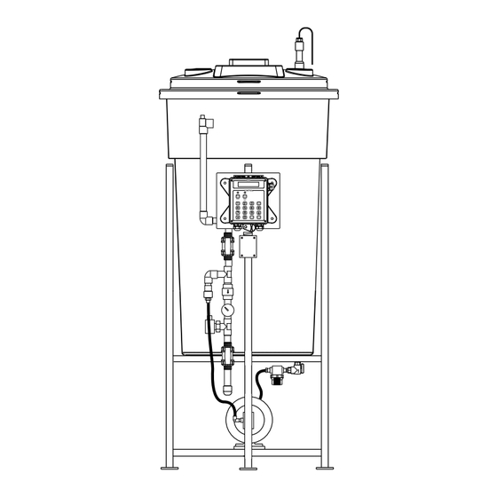
Page 5: Typical Installation And Measurements
Typical Installation and Measurements System Connection Circulation Pump GLYCOL STAND FOOT PRINT 1/4” bolt hole drilled 3/4” from outside edge Note: This is for mounting holes only. Controller will extend beyond this depth. 30 gal 23 ¾” 51” 27 ½” 25 ½” 30 ½”... -
Page 6: Start Up And Test Procedure / Recommendations
Start Up and Test Procedure / Recommendations 1. Before filling tank, be sure that the tank and the filter bowl are free of packing material and or construction debris. 2. Check plumbing as it may have become loose from vibrations during shipping. 3. Fill Tank 4. Open isolation valve to system. 5. If there are no leaks verify that the pressure gauge agrees with system pressure. This value may vary do to connection to Hydronic systems placement. -
Page 7: Digital Front Panel Description
Digital Front Panel Drawing Digital Front Panel Description READ: 1x16 (1/4”) Alpha Numeric Display. CONTROL: Relay 1, Relay 2 - HOA switches for control relays. SET UP SET UP/RUN key - System initializes into RUN mode. Press this switch to toggle the controller from SET UP mode to RUN mode. UP/DOWN arrows - Used to change the display from one line to the next. -
Page 8: Digital System Operation Overview
Digital System Operation Overview MicroTron controllers have two modes of operation, RUN and SET UP. Both the RUN and SET UP menus are circular. Pressing the DOWN key in either menu will display the next line of information on the display. After the last item in a menu has been displayed, pressing the DOWN key will return the display to the top line of that menu. -
Page 9: Calibration
CALIBRATION -- CALIBRATION -- CALIBRATE XXX psi This menu is used to change the display system ENTER (DAGF-2 systems have additional options. pressure. After the unit is properly installed and when Continue cycling down for each system.) power is supplied to the controller, the display will read PRESSURE XX psi. -
Page 10: Pressure Set
PRESSURE SET (1 & 2) -- PRESSURE SET (1 & 2) -- CUT-IN XXX psi This menu is used to used to set the on and off ENTER (DAGF-2 systems have two separate pressures for the pump (or pumps in the case of a PRESSURE SET menus.) dual system). -
Page 11: Clock Set
CLOCK SET -- CLOCK SET -- SET TIME XX.XX (HH.MM) This menu is for adjusting the time, date and day of ENTER the week. To change time After entering a new value, hit the ENTER key to CLEAR accept the value and advance. To accept value keyed in ENTER The clock time is based on a 24 hour clock. -
Page 12: System Set
SYSTEM SET -- SYSTEM SET -- PASSWORD XXXX This menu is used to configure the controller to specific ENTER operational needs. All of the items in this menu may not apply depending on the controller model but will always be present. To change password CLEAR NOTE: Do not use this menu to make calibration To accept value keyed in adjustments. -
Page 13: Diagnostics
DIAGNOSTICS -- DIAGNOSTICS -- MODEL # DAGF This menu is used to select, enter and test the following items. FIRMWARE V.(n) MODEL NUMBER - Read only screen. FIRMWARE VERSION NUMBER - Read only screen. TEST DISPLAY Have both available for service Display will flash (all spaces should TEST DISPLAY - Press ENTER and all pixels will light) press ENTER again to finish ENTER... -
Page 14: Level Set
LEVEL SET -- LEVEL SET -- LEVEL ONE ENABLED LEVEL ENABLE - Enable and Disable options allow for the activation or deactivation of the control logic that governs the input of the level wand(s). Up to four LEVEL ONE DISABLED ENTER level wands can be used simultaneously. LEVEL: PUMP - Each level wand, in the Enabled LEVEL ONE: NO PUMP state, can be used to control the high voltage relay... -
Page 15: Parts List
3. Tank for 30gl = AGF-APCT-30; for 55 gl = AGF-APCT-55 4. Pressure relief valve = AGF-PRV 5. Controller (for selection A) = DALL-GF-V 6. Isolation valve = BV-3/4 for PVC; GV-3/4 for copper 7. Back check = CKV-3/4PP for PVC; CKV-3/4B for copper 8. - Page 16 No. 530 Calibrated Pressure Relief Valve Features A calibrated adjustment feature for setting the valve to the relief pressure required. All Bronze construction All stainless steel springs Specifications Sizes ½” and ¾” (15 and 20 MM) Inlet (bottom) is male threaded, NPT Outlet (side) is female threaded, NPT.
- Page 17 Parts List...
-
Page 18: Digital Controller Wiring
VII. Digital Controller Wiring Dual Loop or Single Loop Pressure Sensor Single Loop - Fuse Box with 2 pumps - Fuse Box (Controller) R W W R W W R COM (Pump #1) N.O. N.C. R COM N.O. N.C. N.C. N.O. -
Page 19: Troubleshooting And Maintenance
VIII. Troubleshooting & Maintenance The Advantage Glycol Feeder is designed for many years of trouble free operation. Should a problem occur, refer to the following chart to help identify the problem. If replacement is required, follow the procedures listed in the Warranty and Factory Service portion of this manual. NO POWER TO UNIT, POWER PRESENT AT RECEPTACLE This happens if the power cord is tripped over or gets caught and pulled by accident. - Page 20 • If Yes, inspect end of level wand for debris or damage, replace if needed. (The float at bottom of the wand should have free movement, up and down. • If No, inspect wire for damage. If no damage visible inspect internal wiring. (See NO POWER TO UNIT, POWER PRESENT AT RECEPTACLE 1 thru 10 above) If no resolution is found, record Serial / Model numbers and call customer service LOW LEVEL ALARM STAYS ON Disconnect level wand connection and short across connectors with screw driver.
-
Page 21: Warranty
Manufacturer’s Product Warranty Advantage Controls warrants units of its manufacture to be free of defects in material or workmanship. Liability under this policy extends for 24 months from date of installation. Liability is limited to repair or replacement of any failed equipment or part proven defective in material or workmanship upon manufacturer’s examination. - Page 24 Get the Advantage in Water Treatment Equipment Advantage Controls can give you the Advantage in products, knowledge and support on all of your water treatment equipment needs. Cooling Tower Controllers Boiler Blow Down Controllers Blow Down Valve Packages Solenoid Valves Water Meters Chemical Metering Pumps...
Need help?
Do you have a question about the GF and is the answer not in the manual?
Questions and answers