
Subscribe to Our Youtube Channel
Related Manuals for Campbell 0871LH1


Summary of Contents for Campbell 0871LH1
- Page 1 0871LH1 Freezing Rain Sensor December 2008 Copyright © 2007 Campbell Scientific (Canada)Corp.
- Page 2 WARRANTY AND ASSISTANCE This equipment is warranted by CAMPBELL SCIENTIFIC (CANADA) CORP. (“CSC”) to be free from defects in materials and workmanship under normal use and service for twelve (12) months from date of shipment unless specified otherwise. ***** Batteries are not warranted.
-
Page 3: Table Of Contents
Program Examples........................ 9 CR23X .......................... 9 CR1000 ........................10 APPENDIX A RS-422 Output Format for non-Campbell Datalogger Applications........12 Built In Test (BIT) ......................12 Hardware Built-In-Test (BIT)..................... 12 Continuous Built-In-Test (BIT)..................12 BIT Failure That Disables Ice Output ................13 Operator-Initiated Tests ...................... - Page 4 TABLE OF FIGURES Figure 1. MSO Circuit Schematic……………………………………………………………….5 Figure 2. MSO Circuit Sectional View………………………………………………………….5 Figure 3. Freezing Rain Sensor….………………………………………………………………6 Figure 4. Mounting………………………………...…………………………………………….7 Figure 5. Power Supply Connections…..………...…………………………………………….8 Figure 6. General Hook-up Diagram……………...……………………………………………..8 Figure 7. Functional Block Diagram……………...……………………………………………20...
-
Page 5: Purpose
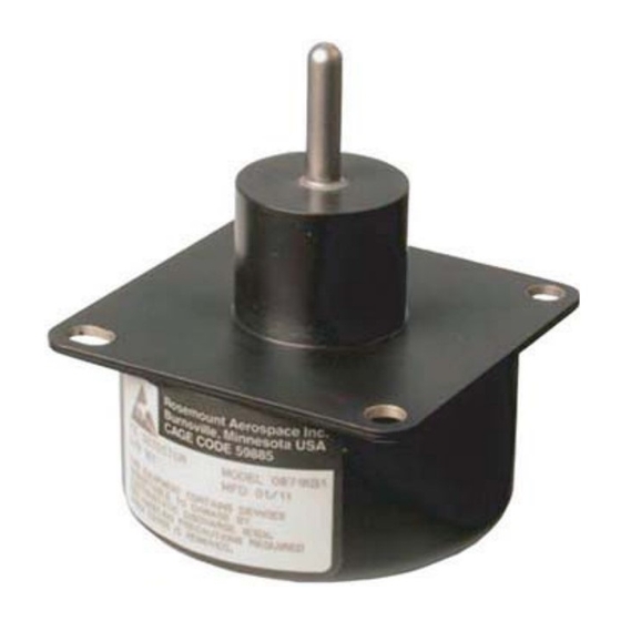
General The Rosemount Aerospace 0871LH1 Freezing Rain Sensor is a one-piece unit that detects the presence of icing condition. Twenty-four volts DC input power is provided to the freezing rain sensor. The freezing rain sensor outputs include ice detection indication and fault status indication. - Page 6 sensing probe. The added mass of accreted ice causes the frequency of the sensing probe to decrease in accordance with the laws of classical mechanics. A 0.020” (0.5 mm) thickness of ice on the probe causes the operating frequency of the probe to decrease by approximately 130 Hz.
-
Page 7: Figure 1 Mso Circuit Schematic
Figure 1 MSO Circuit Schematic Figure 2 MSO Circuit Sectional View... -
Page 8: Physical Description
Physical Description The freezing rain sensor is an integrated unit containing both the sensor and processing electronics. It contains a 2.9” (7.35 cm) square faceplate for mounting to the 0871LH1MNT and a 2.86” (7.28 cm) diameter housing containing the processing electronics. The unit weighs 0.7 lbs. -
Page 9: Mounting Considerations
Mounting Considerations Figure 4 Mounting (part #0871LH1 MNT) The freezing rain sensor should be mounted to a sturdy crossarm located away from buildings or other obstacles that could shadow the sensing element from freezing rain. The sensor should be installed so that the sensing probe is a minimum 36 inches above the ground. -
Page 10: Wiring Diagram
Wiring Diagram - using cable Part # 0871LH1CBL-L Datalogger Connections Description Colour CR3000/CR1000 CR10X/CR510 Blue Control Port* Control Port* Status Yellow Control Port* Control Port* Power Reference Black Case GND Green 5V Power Purple Shield Clear *cannot share control ports Power Connections to Terminal Expander 24 VDC 24V-... -
Page 11: Program Examples
Program Examples CR23X 1: Timer (P26) 1: 3 Loc [ Timer 2: If (X<=>F) (P89) 1: 3 X Loc [ Timer 2: 3 >= 3: 61 4: 30 Then Do 3: Set Port(s) (P20) 1: 9999 C8..C5 = nc/nc/nc/nc 2: 9988 C4..C1 = nc/nc/input/input ;This Section will read the status of the ports for comparison. -
Page 12: Cr1000
1: 2 X Loc [ IceStat ] 2: 1 3: 0 4: 30 Then Do 13: Do (P86) 1: 10 Set Output Flag High (Flag 0) 14: Set Active Storage Area (P80)^10755 1: 1 Final Storage Area 1 2: 20 Array ID 15: Real Time (P77)^8112 1: 1220... - Page 13 PortsConfig (&B11,&B00) Scan (5,Sec,0,0) PanelTemp (PTemp,250) Battery (Batt_volt) TimeCount = Timer (1,Sec,0 ) If TimeCount >= 61 then Portget (IceSignal,1 ) PortGet (StatusSignal,2) If StatusSignal = 1 then CallTable Stat EndIf If IceSignal = 0 then CallTable Ice Timer (1,Sec,3) EndIf EndIf CallTable Info...
-
Page 14: Rs-422 Output Format For Non-Campbell Datalogger Applications
Appendix A RS-422 Output Format for non-Campbell Datalogger Applications This output operates at 9600 BAUD (One Start Bit, 8 Data Bits, No Parity, One Stop Bit). A 24-byte string is sent once per second. See section 10.2 for string definition. -
Page 15: Bit Failure That Disables Ice Output
Continuous BIT consists of verifying the following: • The probe heater is in the correct state. The return leg of the heater is monitored. • The ICE discrete output is in the correct state. The ICE discrete output is fed back to the microcontroller through a passive voltage divider and voltage comparator. -
Page 16: Operator-Initiated Tests
Table 1. BIT Information Disable Ice Initiated Continuous Detection Title MSO Fail, High MSO Fail, Low EEPROM Fail RAM Fail ROM Fail Watchdog Fail Power Interrupt Timer Fail Power Fault Monitor Fail Active Test Passive Test Probe Heater Always ON or OPEN Active Test Passive Test Probe Heater Always OFF... -
Page 17: Initiated Built-In-Test (Bit)
thus changing the frequency and tripping the probe, the voltage reading will immediately drop to a reading below 500mvDC. Observing this will verify that the probe is operating properly and give the user enough time to release the probe before it reaches its full heating temperature. -
Page 18: Correlation Counting
• Resets due to unknown reasons (such as reset from the watchdog timer) are detected. Initiated BIT will examine the RESET EEPROM input. If the input is active, the STATUS output will be set to FAIL and the ICE output and probe heater will be disabled. (This feature allows a factory technician to perform the MSO capacitor selection process without activation of the probe heater.) Activation of the Press-to-Test (PTT) input for greater than 100... -
Page 19: Ice Detector Rs-422 String Format
Ice Detector RS-422 String Format Table 3. Serial String Format Byte Definition Comments/Interpretation/Range String ID Presently defined as 00 0 (First) 7 (MSB) May add additional strings in future 5 - 3 Unused Probe Heater State 1- Heater On 0- Heater Off Ice Output 1- Ice 0- No Ice... - Page 20 Table 3. Serial String Format continued 5 - 7 ON-TIME CNT Power-On Time (In Hex) in 10-Minute Increments 00 - 01FFFF 8 - 9 COLD START CNT Cold Start Power-On Count 00 - FFFF 10-11 ICE CNT Ice Events 00 - FFFF 12 - FAIL CNT Total Failures Encountered.
-
Page 21: Electrostatic Discharge (Esd) Consideration
Electrostatic Discharge (ESD) Consideration The freezing rain sensor internal components are ESD sensitive, class 1, so proper ESD precautions must be observed (wrist straps, conductive surfaces) when handling. -
Page 22: Freezing Rain Sensor Block Diagram
Appendix B Freezing Rain Sensor Block Diagram The block diagram in Figure 4: Functional Block Diagram provides an understanding of the functionality of the freezing rain sensor. Figure 7 Functional Block Diagram... -
Page 23: Microcontroller
Microcontroller The freezing rain sensor uses an Intel 87C51-type microcontroller to control the freezing rain sensor functions. This 8-bit microcontroller requires at least: 4 Kbytes of on-board ROM, 128 bytes of RAM, and 32 input/output ports. The freezing rain sensor uses about 75% of these resources. Upgraded microcontrollers that provide more resources are available. -
Page 24: Heater Control
the frequency decreases, and it is this frequency change that the microcontroller annunciates in the form of Ice Signal #1. Heater Control The heater control turns the probe heater on and off as commanded by the microcontroller and monitors the actual heater state (ON or OFF) for verification by the microcontroller. -
Page 25: Status Output
microcontroller to store the current unity status in the non- volatile memory. The DC power supply provides input transient protection to meet RTCA DO-160C power input, voltage spike, and lightning requirements. Status Output 1.10 The status output provides a ground output when the freezing rain sensor is operating correctly, and high impedance (200 KΩ... -
Page 26: Qualification Capabilities
Qualification Capabilities 0871KB Ice Detector Qualification Capabilities Test Name Test Requirement DO-160C: Audio Freq Susc: Cat Z Induced Signal: Cat Z Susc: Chg Notice 3, Cat R RF Susceptibility: Cat Z RF Emissions: Cat Z Lightning Induced Susceptibility DO-160C: Multiple Burst: Waveform 3 &... -
Page 27: Input/Output Specification
Input/Output Specification Input/Output Pin Designations Table 2. Input/Output Pin Designations Signal Name Con- Input or Definition Current Wire nector Output Gauge 1.5 Amp Max at 24VDC Input 18-29.5 VDC** 28VDC 24VDC Return Input ---- ---- Case Ground Input ---- ---- RS-422 High Output Per RS-422 Spec...
Need help?
Do you have a question about the 0871LH1 and is the answer not in the manual?
Questions and answers