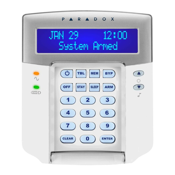
Paradox K32LCD+ Quick Install Manual
Hide thumbs
Also See for K32LCD+:
- Installation manual ,
- Quick start (2 pages) ,
- Quick install manual (2 pages)
Advertisement
Technical Specifications
Operating Voltage 9 to 16Vdc
Operating Temp. -10 to 55°C (14 to 131°F)
Power Consumption Maximum current - 150mA
Dimensions 15 x 12.6 x 2.7 cm (6 x 4.9 x 1.06 in.)
Weight 230g (8.1 oz)
Humidity 5-93%
Compatible with MG5000, MG5050, and Spectra
SP series V2.31 or higher and SP4000, SP65 V4.90
or higher.
Compliance EN50131-3 Grade 2; Environmental Class II
Warranty
Warranty: For complete warranty information on this product, please refer to the
Limited Warranty Statement found on the Web site www.paradox.com/terms. Your
use of the Paradox product signifies your acceptance of all warranty terms and
conditions.
© 2014 Paradox Ltd. All rights reserved. Specifications may change without prior
notice.
www.paradox.com
This device complies with Part 15 of the FCC Rules.
Operation is subject to the following two conditions:
(1) This device may not cause harmful interference, and
(2) This device must accept any interference received, including interference
that may cause undesired operation.
Printed in Canada | 06/2014
K32LCD+ Keypad
Quick Install Guide
The K32LCD+ keypad allows you to configure your Paradox
system through its interface.
Installation
1.
Using a flathead screwdriver, pry the front housing assembly
from the backplate.
Figure 1: Opening the K32LCD+
K32LCD+-EI00
K32LCD+ Quick Install Guide
Advertisement
Table of Contents

Summary of Contents for Paradox K32LCD+
- Page 1 Warranty Warranty: For complete warranty information on this product, please refer to the Limited Warranty Statement found on the Web site www.paradox.com/terms. Your use of the Paradox product signifies your acceptance of all warranty terms and conditions. Installation © 2014 Paradox Ltd. All rights reserved. Specifications may change without prior Using a flathead screwdriver, pry the front housing assembly notice.
- Page 2 Mount the backplate to the wall by securing a M3.5 (#6) Assemble both items by joining the hooks on the backplate screw in each of the dedicated mounting holes and tamper to their respected slots on the front housing assembly. hole.


Need help?
Do you have a question about the K32LCD+ and is the answer not in the manual?
Questions and answers