Advertisement
Quick Links
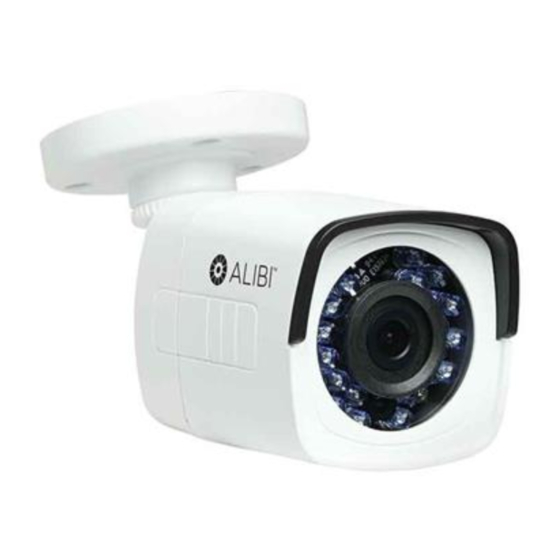
ALI-TS3012R 2MP HD-TVI
Outdoor IR Bullet Camera
Quick Installation Guide
The ALIBI ALI-TS3012R camera feature a 2MP CMOS image sensor that delivers high-definition video
resolution over RG59 coax or any standard analog CCTV cabling up to 1600 ft. This camera must connect
to an HD-TVI compatible DVR, such as an ALIBI HVR. This HD video camera is ideal for security applications
that require a high level of detail, such as facial recognition.
Features
2MP CMOS image sensor
•
HD-TVI technology produces 1920 × 1080 (1080p)
•
2.8 mm wide angle (103° field of view) lens captures images over large areas
•
HD-TVI technology transmits zero latency HD video resolution over coax cabling
•
Smart IR full frame technology with range up to 65 ft
•
14 °F ~ 122 °F temperature operating range
•
IP66 weather-rated housing
•
Must be used with a compatible ALIBI HD-TVI DVR
•
Can be installed with optional ALI-AJ6 junction box
•
Adjustable
mounting
bracket
Camera body
IR LED Array
Camera drop cable connectors
What's in the box
Camera assembly
•
Mounting hardware
•
This instruction guide
•
Drill template
•
Tools you need
To install the camera, you will need:
12 Vdc power source. See Specifications for wattage requirement.
•
Tools and additional fasteners (may be required) for mounting the camera
•
Phillips screwdriver
•
Video and power extension cable
•
www.observint.com
1
Installation
Before installation:
•
•
•
•
During installation:
•
•
•
Step 1.
These cameras can be mounted directly onto a wall or ceiling, or with a junction box. The surface on which
it is installed must support at least three times the weight of the camera (and junction box if used). The
video/power drop cable from the camera can be routed either through mounting surface, through a cable
guide on the edge of the mounting base, or into the junction box for connection to the video and power
Mounting base
extension cables.
Lens
HD-TVI video
BNC connector
Power
•
Connector
1.
2.
3.
4.
5.
6.
7.
Make sure that the device is in good condition and all the assembly parts are included.
Check the specification of the products for the installation environment.
Make sure that the wall or the ceiling is strong enough to withstand 3 times the weight of the camera.
To avoid fire or shock hazard, use only UL listed power supplies. Verify that the power supply will
provide the rated voltage and wattage for the camera. See the Specifications section.
Camera Lens: Handle the camera carefully to prevent scratching or soiling the lens. If the lens or IR
array shield becomes soiled, clean it only with approved products. See the
Monitor impedance: Set the monitor impedance switch to 75 Ω.
Power supply: Camera drop cable: The camera drop cable includes two connectors:
Video BNC connector: For transmission of the video signal across a coax (75 Ω) extension cable.
—
Power connector: When applying Vdc power, observe the power polarity. See the drop cable
—
photo to the left for the connector polarity configuration.
Mounting the camera
Typical ceiling mounting
If mounting the camera on a wall, ensure that the cable guide in the mounting base, is down.
NOTE
If mounting the camera on a ceiling, orient the mounting base so that the cable guide is pointing
away from any source of water, dust, and other contaminates.
Mounting the camera directly to a wall or ceiling
Using the drill template provided, mark the location of the screws that anchor the mounting base
to the mounting surface. See the note above. If you are routing the drop cable through mounting
surface, also mark the position of the hole for the drop cable.
Drill holes for the screws that anchor the base to the mounting surface. The mounting hardware
provided is appropriate for most surfaces. However, depending on the surface materials, more
appropriate fasteners may be required.
Drill a 3/4" hole through the mounting surface for the drop cable, if necessary.
Route the drop cable through the hole in the mounting surface, or through the cable guide in the
mounting base, then attach the camera assembly to the surface using the appropriate fasteners.
Connect the camera drop cable to video and power extension cables.
Connect the other end of the video extension cable to a video monitoring device, such as a HD-TVI
capable DVR.
Drop cable connectors are not waterproof.
NOTE
Connect the other end of the power extension cable to a 12 Vdc power source. Observe the polarity
of the cable shown in the photo on page 1 of this guide.
section.
Cleaning
ALI-TS3012R_CQ
161004
Advertisement

Subscribe to Our Youtube Channel
Related Manuals for ALIBI ALI-TS3012R


Summary of Contents for ALIBI ALI-TS3012R
-
Page 1: Quick Installation Guide
See the Specifications section. resolution over RG59 coax or any standard analog CCTV cabling up to 1600 ft. This camera must connect to an HD-TVI compatible DVR, such as an ALIBI HVR. This HD video camera is ideal for security applications During installation: that require a high level of detail, such as facial recognition. -
Page 2: Troubleshooting
Mounting the camera with a junction box Specifications • The ALI-AJ6 junction box is shown below. It can be attached to a wall or ceiling. Video and power Camera extension cables can be routed in through the opening in the back of the box or through the conduit Image Sensor 2MP CMOS Image Sensor coupling, and attached to the camera drop cables inside the enclosure.
Need help?
Do you have a question about the ALI-TS3012R and is the answer not in the manual?
Questions and answers