Table of Contents
Advertisement
Quick Links
Advertisement
Table of Contents

Related Manuals for BK Precision 603B


Summary of Contents for BK Precision 603B
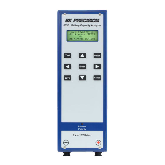
- Page 1 Battery Capacity Analyzer with record storage 603B User Manual...
- Page 2 Safety Summary The following safety precautions apply to both operating and maintenance personnel and must be followed during all phases of operation, service, and repair of this instrument. WARNING Before applying power to this instrument: ● Read and understand the safety and operational information in this manual. ● Apply all the listed safety precautions. ● Verify that the voltage selector at the line power cord input is set to the correct line voltage. Operating the instrument at an incorrect line voltage will void the warranty. ● Make all connections to the instrument before applying power.
- Page 3 WARNING Do not use this instrument in an electrical environment with a higher category rating than what is specified in this manual for this instrument. WARNING You must ensure that each accessory you use with this instrument has a category rating equal to or higher than the instrument’s category rating to maintain the instrument’s category rating. Failure to do so will lower the category rating of the measuring system. Do not operate in an explosive or flammable atmosphere WARNING Do not operate the instrument in the presence of flammable gases or vapors, fumes, or finely-divided particulates.
- Page 4 Do not operate instrument if damaged WARNING If the instrument is damaged, appears to be damaged, or if any liquid, chemical, or other material gets on or inside the instrument, remove the instrument’s power cord, remove the instrument from service, label it as not to be operated, and return the instrument to B&K Precision for repair. Notify B&K Precision of the nature of any contamination of the instrument. Clean the instrument only as instructed WARNING Do not clean the instrument, its switches, or its terminals with contact cleaners, abrasives, lubricants, solvents, acids/ bases, or other such chemicals.
-
Page 5: Table Of Contents
Table of contents GENERAL OPERATING INSTRUCTIONS ....................6 Ready The 603B ..............................6 BUTTON DESCRIPTIONS ........................8 QUICK TEST MODE – SOC ........................9 3.1 Quick Test Mode - Pass/Fail ..........................11 3.2 Quick Test Mode - Charger Circuit Test ......................12 MAIN MENU ............................14 View/Edit Records .............................. 14 Record Indicators .............................. 15 4.3 Database Record Format ..........................16 4.3.1 System type field .......................... -
Page 6: General Operating Instructions
1 General Operating Instructions This section describes general operating instructions that apply to all of the testing modes. Before connecting the 603B to any battery or circuit read and follow the information provided in the safety section. Verify the voltage and current is within the safe operating range of the 603B. Refer to the Specifications section. The 603B is powered by the battery or charger circuit under test. The 603B does not have a power switch and will power on and display the voltage when the properly connected to a battery with sufficient power. If nothing is displayed or the display blinks on and off the power is not sufficient and testing cannot proceed. 1.1 Ready The 603B 1. Two types of cables are available for use with the 603B. One set is intended for smaller batteries that connect with tab type connectors and the other set has larger jaws to accommodate batteries with bolt on or clamp type terminals. Select the cable type that will make the best connection with the battery to be tested. Tab type Terminal type 2. Identify the cable ends with the 3-pin twist lock connector. One of the cables will have a red band on the end near the 3-pin connector. This cable will be installed in the positive side of the 603B identified with the red plus sign... - Page 7 The outer ring can now be rotated until the groves align and the ring move slightly forward. Continue to gently push the connector forward while twisting the outer ring. The outer ring should easily turn clockwise ¼ turn locking the two mating connectors together. Gently pull on the shell of the connector to make sure the cable is locked into place. Install the Remaining negative cable in the same manor. 5. If the system has 2 batteries, test each battery separate. 6. The 603B use a 3 wire connection to improve accuracy. This requires both sides of the each alligator clip to make a good connection between the jaws of the alligator clip and the terminal. Good Connection Bad Connection Both sides of the alligator clip are making In these two examples one side of the good connection to the battery terminal.
-
Page 8: Button Descriptions
2 Button Descriptions This section provides an overview of each button and its description, refer to Table 1. Some buttons will have different functions additional detail is provide in the section where the button is used. Button Description Starts the test Opens the option menu and on-screen keyboard Move the cursor up one space or move to the previous page Move the cursor down one space or move to the next page Move the cursor left one space Move the cursor right one space Select the row or select a character using the on-screen keyboard. Save changes to the internal database memory Cancel the operation move back one menu level Table 1 Battery Capacity Analyzer User Manual... -
Page 9: Quick Test Mode - Soc
This feature supports testing batteries of the same type without the need of reentering the ampere hour value each time the meter is disconnected and reconnected. It’s important to remember that the Quick Test mode does not save measurement results. 1. Disconnect the battery or batteries from the charger circuit. Dress the charger circuit leads so they do not come in contact with each other or any other conductive parts of the cabinet or control board. 2. Verify that battery voltage and Ah, is within the specifications of the 603B. 3. Connect the battery observing the correct polarity. VO = 12.78 Volts Quick press [TEST] Main press [ENTER] Power on - Main screen 4. Press the button once to select Quick Test. - Page 10 7. The back light will turn off indicating the test has started. To cancel the test, press the button. 8. The back light will illuminate after approximately 6 seconds and the results will be displayed. BATTERY QUICK TEST VO : 12. 77 SOC : 90 VL : 12. 28 IR : 24m RS : N/A Result screen Tip: After completing the test, the cables can me moved to a new battery of the same type. 1. Once the next battery is connected, press the button twice, press once to select Quick Test mode and again to start the test. If the battery has a different Ah: value 2. Use the buttons to change the value followed by the button. Battery Capacity Analyzer User Manual...
-
Page 11: Quick Test Mode - Pass/Fail
3.1 Quick Test Mode - Pass/Fail The Pass/fail option compares a batteries’ internal resistance to a known good nominal value and determines if the battery under test is PASS or FAIL. The Nominal Internal Resistance or “NIR” value is optional. If the NIR is set to the default of value of N/A the 603B will display RS: N/A. The NIR entered is compared to the battery under test measured IR. If the battery under test is less than or equal to 160% of the NIR value the 603B will display “RS: PASS” in the field. If the value is above 160% the 603B will display “RS: PASS” in the field. Example: The NIR is set by the user to 23 milliohms then the threshold can be calculated: 160% X NIR = 1.6 X 23 = 36.8 If the 603B measured IR is equal to or greater than 36.8 the 603B will display RS: FAIL Three methods can be used to determine the “NIR” value to be enter. 1. Find the IR value on the battery manufacturer’s data sheet. 2. Use the 603B to measure the IR of a known good battery of the same type. 3. Use another battery analyzer like the B&K Precision model BA6010 to measure batteries’ IR. Note: The known good battery should be new and made by the same manufacturer with the same model number. 1. Set the Ah value as describe in Quick Test, SOC section. If the Ah value is correct move to the next step. 2. Press the button to move the cursor over to the “NIR = …“ field. The range includes N/A and 1 to 100. Press and hold is also supported for rapid changes. 3. Enter the NIR using the buttons. Press and hold is also supported for rapid changes. 4. Press the button to proceed. The NIR entered is compared to the battery under test measured IR. If the battery under test is less than or equal to 160% of the NIR value the 603B will display will indicate PASS in the “RS:” field. If the value is above 160% the 603B will display will indicate FAIL. This percentage cannot be changed BATTERY QUICK TEST VO : 12. 66 SOC : 90 VL : 12. -
Page 12: Quick Test Mode - Charger Circuit Test
Charger adapter An adapter is provided with an F1 tab on one end and F2 tab on the other. Using the correctly sized tab, plug one end of the adapter into the leads of the system charger circuit. The other end of the adapter is used for an attachment point for the 603B tab type, alligator clips. 1. Connect the 603B cables and verify the positive and negative leads are correct and the Reverse Polarity LED is not illuminated. VO = 12.78 Volts Quick press [TEST] Main press [ENTER] 2. Press the button to move to the Quick Test menu. - Page 13 Press TEST or CANCEL Both “OCV:” and “LCV:” will be measured and displayed. If the LCV voltage is significantly below the OCV: the voltage charger circuit could have a problem. Contact the control panel (charger), manufacturer for more information. The back light will turn off indicating the test has started. Both the open voltage OCV: and the loaded voltage LCV: are displayed. If the LCV drops will below the OCV value the charger circuit regulator could be faulty. The results of the test must be interpreted by the technician as each type of charger circuit is different. Contact the charger circuit manufacture for more information. Tip: In a two battery system use the Ah value of one battery. Example, a fire alarm control panel has two 12 V batteries connected in series to provide the FACP with 24 volts. The charger circuit in the FACP is designed to charge at just over 24 volts. The 603B will use this Ah value of one of the batteries to calculate and apply a parcel load on the charger circuit. Battery Capacity Analyzer User Manual...
-
Page 14: Main Menu
4 Main Menu The Main menu provides access to Record Mode, additional test tools and system configuration. 1. Connect the 603B and verify the displayed voltage is in range. VO = 12.78 Volts Quick press [TEST] Main press [ENTER] Power on menu 2. To access the Main menu level by pressing the button View Edit Records Add New Record Load Test System Mani menu The Main menu has four options available. Each of these options is explained below in more detail. 4.1 View/Edit Records To view or edit an existing record in the 603B memory. 1. Power on the 603B. 2. Press the button to select the Main Menu. 3. Use the buttons to move the pointer to the row “View/Edit Records” and press the button. -
Page 15: Record Indicators
To view a specific record in the database. 4. Press the button to move the cursor over to the Record number field. 5. Press the to increment or decrement through the existing records. If the record exists the record will be displayed on the screen. If the record exists but is empty you will only see the field labels with no data in the field. The 603B will step through all the records in memory and start over. 6. To edit the record field, use the buttons to move the pointer to the row to be edited. 7. Press the button to move the cursor in to field. If the cursor does not move in to the field this field cannot be modified. In the example shown, Dat: and Tme: are system type fields and cannot be modified. The Bld: field can be edited and the on screen keyboard will be displayed when in the edit mode. See Database record format and on-screen keyboard for more information. Rec: 001 Dat: Tme: Bld: Record View example 4.2 Record Indicators The small arrow “Item selector pointer” in the top left corner of the example screen is used to select a row or move to another screen. This indicator is moved up or down the left side of the screen using the buttons. -
Page 16: Database Record Format
4.3 Database Record Format The 603B can store up to 50 records in the internal memory. Existing records can be selected, viewed and edited. A new 603B will have only one record number 001 in memory. This record will have no data in the fields also called a blank or empty record. You can use the View/Edit Records to add information in the User editable fields. Each record contains 31 fields refer to table 2 for more details. The first column, Displayed Field shows the mnemonic label as displayed on the 603B. The second column provides clarification of the mnemonic label. The third column provides information about the type of data that is stored in the field and the last column describes the size and format. The only fields that can be edited by the user are Data Type, “User”. All the other fields in the record are controlled by the 603B system and cannot be edited by the user. Displayed Field Data Size Record System 2 digits, numeric, 50 records Date System yyyy/mm/dd Time System hh:mm:ss, 24 hour Building User 13 character, alphanumeric Location User 13 character, alphanumeric System type, see table 3 User 1 character, predefined Battery Serial Number User... -
Page 17: System Type Field
Prompt Access Control Backup CCTV Exit Light Fire Control Panel Fire Control Panel Charger Fire Extender Panel Fire Extender Panel Charger Security Other Table 3 The 603B displays a reminder prompting the user to test the charge circuit after some tests. To keep the 603B from prompting twice in a two battery system like fire alarm, system types F and E are used. The prompt is not displayed for system types F and E as this step will be performed after battery types R and X are tested. The 603B will display the battery serial number stored in the record to make it easy to verify the correct battery will be tested. 4.3.2 On-screen keyboard Some of the user editable fields except alphanumeric characters. The 603B will switch to edit mode displaying the on-screen keyboard for any alphanumeric field. The label at the top of the screen and keyboard for selecting letters numbers and symbols. The buttons are used to move the cursor. Bld : Bld : Gym 0123456789@#$ & : ;... -
Page 18: Numeric Type Fields
4.4 Add New Record The new blank record can be added to the database if the database is not full. 1. From the Main menu use the buttons to navigate to the Add New Record. View Edit Records Add New Record Load Test System 2. Press the button to select and add the new record. Example: If the 603B has 11 records and a new record is added it will be assigned to the next logical memory location in this example, 012. Rec: 012 Dat: Tme: Bld: 3. Press the button to keep this new blank record. If desired continue adding information to the record fields. Tip: Be sure to press the button or the changes will be lost. -
Page 19: System
VO : 12.79V VC: 11 . 91V Arrow Keys to Set TEST Key to Test The 603B uses internal temperature sensors to automatically control the cooling fan speed. It is normal for the fan to turn on, speed up and turn back off based on usage. Tip: The System menu allows the user to manually turn on for testing or additional cooling. 4.6 System The System menu is used to view and change the 603B system configuration. This section describe each of these settings. The System menu is accessed from the Main menu. 1. Power up the 603B, press the button. Five rows are presented on the Main Menu. 2. Use the keys to move the point to the “Systems” row and press the button. View Edit Records Add New Record Load Test System Main Menu level Battery Capacity Analyzer User Manual... -
Page 20: Setting Date
4.6.1 Setting date The date needs to be set when the 603B is new or has been factory restored. The date is recorded in the database after each test when using Record Mode. To set or change the date 1. Use the buttons to move the pointer to the “Date:” row. 2. Press the button to advance the cursor to the year field, Month or day field with each press. 3. Use the buttons to increment or decrement the values in the field. 4. When finished, press the button a few times to move the cursor back to the row. The row point will show and the new date will be saved. Date: 2018 05 31 Time : 08 : 21 : 08 Delete Records Factory Restore Selecting the Date: row 4.6.2 Setting time... -
Page 21: Delete Range Of Records
Delete record screen A new screen will be displayed with the cursor located in the Record Number: field. 4. Use the buttons to increment or decrement the record value to be deleted. 5. Verify this is the correct record to be delete and press the button. The record will be deleted immediately without a confirmation. Note: The data in the record is deleted the blank record is keep to keep the record positions in the correct order. 4.6.3.2 Delete range of records To delete a range of records in the 603B memory, 1. Power on the 603B and press the button to select the Main Menu. Press ENTER to Del . Select Number Range Del . from 001 to 002 Delete range 2. Use the buttons to move the pointer to the last row called “System” and press the button. 3. Use the buttons to move the pointer to “Delete Records” and press the button. Battery Capacity Analyzer User Manual... -
Page 22: Delete All Records
The display will show a cursor located in the “from” field. 4. Use the to increment the number to the first record to be deleted. 5. Press the button to move to the cursor to the last record number field. 6. Use the to increment the number to the last record in the range to be deleted. 7. Verify the range of records is correct as all the records in this range will be deleted. 8. Press the button. The records will be deleted immediately without a confirmation. If the 603B displays “Out of Range” the range is not correct. The starting range must be less or equal to the ending range value. 4.6.3.3 Delete all records To delete all records in the 603B memory, 1. Power on the 603B and press the button to select the Main Menu. Press ENTER to Delete all Data 2. Use the buttons to move the pointer to the last row called “System” 3. Press the button. 4. Use the buttons to move the pointer to “Del. All Records”. 6. Press the button to delete all records. The records will be deleted immediately without a confirmation. 4.6.4 Factory Restore To restore the 603B factory settings and erase all memory, 1. Power on the 603B and press the button to select the Main Menu. -
Page 23: Calibration
5. Use the buttons to increment this digit to 1 6. Press the button to move to the next digit and increment this digit to 3. 7. Proceed in complete all for digits until 13579 is showing in this field. 8. Press the button to proceed. A confirmation screen will be presented providing the option to proceed or cancel. Recover to Default Setting? [SAVE] to Recover [CANCEL] to Leave 9. Press the button, all records will be deleted and the settings will be restored to factory settings. This process will also erases the calibration file and returns the 603B to a default base calibration. Calibration can only be recovered if the last calibration file for the specific 603B was saved and available. If not the 603B should be re-calibrated following the process in the Calibration section. 4.6.5 Calibration The calibration section on page 30 describes the process and equipment needed to calibrate the 603B. The calibration process is made up of several sections. All sections should be competed in full. Read the enter calibration section before attempting. 4.6.6 SOC Profile Settings This section describe the steps used to create a User defined SOC table. The values in the table are used to calculate the remaining battery capacity. The 603B includes two default profile tables one for 6 volt and 12. These two profiles... -
Page 24: Soc Table Selection
1. Power on the 603B. 2. Press the button to select the Main Menu. 3. Use the buttons to move the pointer to the row “System” and press the button. 4. Use the buttons to move the pointer to the row “SOC Profile Settings” and press the button. SOC Pro f ile SOC1 100 = 26 . 214V 90 = 26 . 214V 80 = 26 . 214V Selecting a profile The pointer will be located at the row “Setting 12 V SOC #1” by default. The settings continue to the next screen. A total of 6 profiles can be edited and stored. 3 profiles for both 12 and 6 volt ranges. For this example the default row selected, “Setting 12V SOC #1 opening the profile view and edit screen. Setting 12V SOC # 1 Setting 12V SOC # 2... -
Page 25: Back Light
4. Use the buttons to move the pointer to row “SOC Selection” and press the button. Quick 12V SOC = D Quick 6V SOC = d Record 12V SOC = D Record 6V SOC = d SOC select 5. Use the buttons to move the pointer to select a row for the test mode and voltage desired and press the button to move the cursor in the field and enable editing. 6. Use the buttons to step through the options. 12V has the options: D, 1,2 and 3 while 6V has the options: d,4,5,6. The letters “D” and “d” are default system SOC profiles. The numbers are reserved for user created SOC profiles. 7. When the desired option is showing press the button to return the cursor back to the row with the select pointer showing. 8. Press the Button this will also save the changes and move back one menu level. 4.6.8 Back Light The back light can be toggled On/Off by moving the pointer to this row and pressing the button. Each press of the button will toggle the On/Off state. -
Page 26: Firmware Version
Weighting is an estimating method used to provide a more useful representation of the batteries’ State of Charge (SOC). The user must provide the nominal internal resistance (NIR) value for this feature to function. NIR can be entered in the Quick test mode for using during the Quick test or added to the record for use in Record Mode. When SOC Weighting is turned off the 603B calculates the SOC using the same method as a volt meter and an SOC chart. The batteries open terminal voltage and a lookup table in memory is used to find and estimate the batteries remaining capacity. If SOC Weighting is On the IR and NIR are compared and if the measured IR is not equal to NIR the remaining battery capacity displayed is reduced. Increased battery IR is a normal part of the battery aging process. The weighting algorithm used in the 603B is suitable for most SLA type batteries used in the alarm, CCTV, and access control industries. Three methods can be used to determine the “NIR” value to be enter. 1. Find the IR value on the battery manufacturer’s data sheet. 2. Use the 603B to measure the IR of a new battery. 3. Use another battery analyzer like the B&K Precision model BA6010 to measure batteries’ IR. Note: The known good battery should be new and made by the same manufacturer with the model number. 4.6.10 Firmware Version To view the firmware version, 1. Movie the pointer to this location and pressing the button. SOC Weighting On Firmware Version Fan Start 2. Press the Button to return. 4.6.11 Fan Start The fan start is used to test and verify the fan is functioning correctly. The 603B has an internal temperature sensors. The system will turn on the fan and adjust the speed automatically. -
Page 27: Record Test Mode
Starting Fan Process Fan Off after 5 min CANCEL to Leave 2. Press the button to stop the end the Fan test early and return. Tip: In hot environments with repeated load testing the outside case of the 603B may become uncomfortable hot. This Fan Start feature can be used to help cool the 603B. Load testing should be delayed until the 5 minute timer shuts off the fan. If the case is still hot repeat the Fan Start process. 4.7 Record Test Mode Record Mode testing is used to test the battery and charger circuit and record the resulting in to the 603B memory. The 603B can store information about the battery, system type, site location and more. See Database Record Format section for more details. The minimum requirement to complete a test in this mode is battery Ah: To enter the Record Test mode and compete a test, 1. Power up the 603B, press the button. Rec: 001 Dat: Tme: Bld: Record number 2. Press the button. 3. If the 603B is displaying the correct record number. a. Verify the battery serial number. -
Page 28: Record Mode Charger Circuit Test
5. Keep the default temperature value or use the to adjust the temperature to record a more accurate battery environment. This information is not used in the 603B calculations this is only stored in the database record for future analysis by the user. Tip: Use a none contact thermometer to measure the battery temperature for more accurate database record. 6. Press the button to save the changes to the 603B memory. The 603B will respond with the message “Data Saved”. 7. To test the charger circuit press the button and follow the on-screen instructions. The test leads can be removed from the battery and reconnected to the charge circuit. - Page 29 2. Disconnect the 603B from the battery. The 603B will remember the record in use and return to this record when power is restored ready to test the charge circuit. 3. Connect the 603B cables and verify the positive and negative leads are correct and the Reverse Polarity LED is not illuminated. Use the Tab type adapters if required. Tab adapter CHARGER TEST OCV : 12. 71 LCV : REC: 001 Press TEST or CANCEL Charger screen 4. Verify the OCV: voltage in the expected range. 5. Press the button to begin the test. The back light will turn off indicating the test has started. After a few seconds the back light will illuminate and the results will be displayed. The 603B will display the “OCV:” and “LCV:”. The measurements will also will be stored in the record. CHARGER TEST OCV : 12.
-
Page 30: Firmware Update Procedures
5 Firmware Update Procedures 5.1 Firmware Update Instructions The following section describes the steps to complete a firmware update. The steps include: 1. Downloading and installing the firmware application software called “Bootloader”. 2. Connecting the 603B to the computer. 3. Updating the firmware. 4. Restoring the calibration data. Downloading the Software The Bootloader has been tested on Microsoft Windows 7 and 10. Download the application 603B_Bootloader v1.07 from the bkprecison.com website. This file is zipped be sure to unzip the file before attempting to launch the application. Right click the application and select Run as Administrator. The following screen will be displayed. Connecting the computer The 603B does not require a battery or power supply for this process. The 603B internal processor will be powered by the USB port. The display on the 603B will not be enabled during this operation. Connect the computer to the 603B using a type B USB cable. Updating the firmware After the application launches, change the default COM1 to match the COM assigned by the operating system. To find the correct COM, click the down arrow to open the COM port selection. Battery Capacity Analyzer User Manual... - Page 31 Unplug the 603B from the USB port and observe which COM port disappears. Plug the 603B back in, open the COM selection and select this COM port from the list. In this example the operating system assigned COM4 your system my assign a different COM. 1. Under the heading Firmware File, click on the Open File button. 2. Select the text file FW 1.xx.txt where xx is the correct firmware revision. 3. The path to the firmware selected should now show at the top of window. 4. Click the Open File button. Battery Capacity Analyzer User Manual...
- Page 32 The green progress bar will advanced as the memory is updated and log messages will be displayed. The existing calibration data will be read from the 603B. The log will display “Read Calibration Data OK”. This file will be automatically saved on the host computer with a file name containing “…….Calibration Data.txt”. This file will be used in the Restoring Calibration steps. The bootloader window will display Finish when the update is compete. Battery Capacity Analyzer User Manual...
-
Page 33: Restoring The Calibration Data
5.2 Restoring the Calibration Data The calibration data now needs to be restored. This step is recommended even if you plan to complete the calibration process after the firmware update. 1. Under the section “Calibration File”, click the Open File button. 2. Find the file “…….Calibration Data.txt” create in the previous steps verify the date and time the file was created and select it. The file path should now show in the Calibration File window. 3. Click the upgrade button to start the process. 4. A warning message will now be display click the Yes button. 5. This procees will be followed by a notice to “Please Reinsert the USB cable”. This should read Remove and reinsert the USB cable. Battery Capacity Analyzer User Manual... -
Page 34: Calibration Procedures
The B&K Precision Model 9202 is recommend. Calibration SOC Prof ile Setting SOC Table Selection Back Light On Calibration screen To start the calibration process: 1. Connect the 603B to the specified power supply. The 603B uses a three wire connection for both positive and negative cables. Both sides of the alligator clip must make a good connection to the power supply terminals. 2. Set the power supply 12.000 volts and 2.000 A 3. Enable the power supply output and verify the 603B powers up. The displayed voltage is should be between 9 to 13 volts as the unit is not calibrated at this point. 4. Press the button to select the Main Menu. 5. Use the buttons to move the pointer to the last row called “Calibration” and press the button. The password screen will be displayed. ENTER to Un lock... -
Page 35: Voltage Calibration
6.2 Voltage Calibration This section describes how to calibrate the voltage. The label is easy to confuse as V_Min_1 is similar to V_Med_1 carefully match the values in the tables to the label on the 603B at each step. From table XXX find the voltage for V_Min_1 of 5.40 V and set the power supply to this voltage. 603B Row Voltage Label Setting V Min 1 5.40 V V Med 1 8.00 V V Max 1 18.00 V Press ENTER to Set V Min 1 = 1114 ADC V Med 1 = 1627 ADC V Max 1 = 3607 ADC Voltage screen 1 of 2 9. Verify the pointer is located at the first row “V_Min_1 …”... -
Page 36: Current Calibration
Arrow Keys to Set I Min 1 = 00092 mA I Med 1 = 01466 mA Current Calibration 1 of 4 screens The next few steps are used to calibrate the 603B current 12 calibration points are used over 3 screen views. 21. The button is used to trigger the 603B placing a load on the power supply. Monitor the maximum current used as displayed on the power supply current meter. Make note of the maximum value. Enter this 4 digit value in the row. Repeat until all 12 calibration points are adjusted. Note that the value in the 603B display is in mA and most power supplies display in amps so a conversion will be required. 22. When ready, press the button to trigger the 603B. -
Page 37: Load Calibration
Write the maximum value down. Enter this 4 digit value in the row. Repeat until all three calibration points are adjusted. Note that the value in the 603B is in mA. From the 3 part calibration screen move the point to the row “Load Calibration”. 25. Press the button to select Load calibration Voltage Calibration Current Calibration Load Calibration 26. When ready, press the button to trigger the 603B. 27. Use the button to move the cursor into the Load field and enter the max current displayed on the power supply. 28. Repeat these steps until all Min, Med, Max current values have been calibrated. Note this is spread across 2 separate screens. Press OPTION to TRG Arrow Keys to Set I Min = 00323 mA I Med = 07869 mA Load Calibration 1 of 2... -
Page 38: Specifications
7 Specifications Range 603B Open voltage 5.5 V to 30 V Displayed Battery test 5.5 V to 6.8 V Voltage open 6 Volts Charge circuit test 5.5 V to 8.5 V Voltage loaded Battery test 8 V to 14 V... -
Page 39: Service
8 Service Information Warranty Service: Please go to the support and service section on our website at www.bkprecision.com to obtain a RMA #. Return the product in the original packaging with proof of purchase to the address below. Clearly state on the RMA the performance problem and return any leads, probes, connectors and accessories that you are using with the device. Non-Warranty Service: Please go to the support and service section on our website at www.bkprecision.com to obtain a RMA #. Return the product in the original packaging to the address below. Clearly state on the RMA the performance problem and return any leads, probes, connectors and accessories that you are using with the device. Customers not on an open account must include payment in the form of a money order or credit card. For the most current repair charges please refer to the service and support section on our website. -
Page 40: Limited One-Year Warranty
9 Limited One-Year Warranty B&K Precision Corp. warrants to the original purchaser that its products and the component parts thereof, will be free from defects in workmanship and materials for a period of one year from date of purchase. B&K Precision Corp. will, without charge, repair or replace, at its option, defective product or component parts. Returned product must be accompanied by proof of the purchase date in the form of a sales receipt. To help us better serve you, please complete the warranty registration for your new instrument via our website www.bkprecision.com Exclusions: This warranty does not apply in the event of misuse or abuse of the product or as a result of unauthorized alterations or repairs. -
Page 41: Ce Declaration
10 CE Declaration of Conformity This instrument meets the requirements of 2006/95/EC Low Voltage Directive and 2004/108/EC Electromagnetic Compatibility Directive with the following standards. Low Voltage Directive - EN61010-1 : 2001 EMC Directive - EN61326-1 : 2013 - CISPR11 - EN61000-4-2 : 2009 - EN61000-4-3 : 2006 + A2 : 2010 - EN61000-4-8 : 2010 Reference to our most updated CE info: http://www.bkprecision.com/support/downloads/ce-declarations.html Battery Capacity Analyzer User Manual... - Page 42 B&K Precision Corporation 22820 Savi Ranch Parkway Yorba Linda, California 92887 www.bkprecision.com 2018 B&K Precision Corporation rev080918 Battery Capacity Analyzer User Manual...
Need help?
Do you have a question about the 603B and is the answer not in the manual?
Questions and answers