Advertisement
Quick Links
*15G065046100AK*
P/N: 15G065046100AK V1.0
Quick Installation Guide
EPC612D4I
The server board User's Manual is available for download from the ASRock Rack's official website
at http://www.asrockrack.com.
Take note of the following precautions before you install server board components or change any
server board settings.
1.
Unplug the power cord from the wall socket before touching any components.
2.
To avoid damaging the server board's components due to static electricity, NEVER place your
server board directly on the carpet or the like. Also remember to use a grounded wrist strap or
touch a safety grounded object before you handle the components.
3.
Hold components by the edges and do not touch the ICs.
4.
Whenever you uninstall any component, place it on a grounded anti-static pad or in the bag
that comes with the component.
5.
When placing screws into the screw holes to secure the server board to the chassis, please do
not over-tighten the screws! Doing so may damage the server board.
2
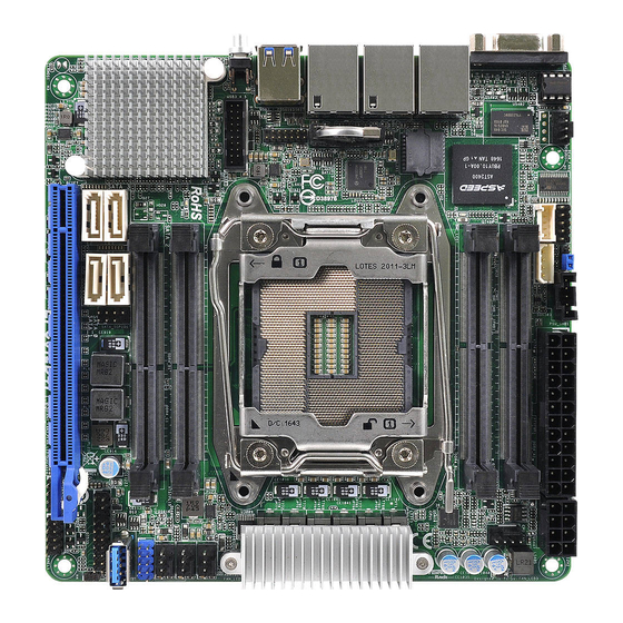
Motherboard Layout
1
2
64Mb
COM1
BIOS
REAR_FAN1
IPMI
LAN
LAN1
LAN2
1
27
USB 3.0
T: USB2
B: USB1
TPM1
UID1
1
USB3_4_5
26
RoHS
Intel
C612
25
3
I/O Panel
1
2
No. Description
No. Description
1
VGA Port (VGA1)
4
2
LAN RJ-45 Port (IPMI_LAN)
5
3
LAN RJ-45 Port (LAN1)
6
3
4
5
6
1
1
ATXPWR1
ME_RECOVERY1
1
PSU_SMB1
1
1
BMC_SMB_1
IPMB1
DDR4_A1 (64 bit, 260-pin module)
DDR4_B1 (64 bit, 260-pin module)
CPU1
DDR4_D1 (64 bit, 260-pin modulee)
DDR4_C1 (64 bit, 260-pin module)
SATA3_2
SATA3_0
1
SATA_SGPIO1
SATA3_3
SATA3_1
PCIE7
EPC612D4I
24
23
22
3
4
5
6
LAN RJ-45 Port (LAN2)
USB 3.0 Ports (USB3_1_2)
UID Switch (UID1)
1
Install the Server Board
1
Insert the server board into the chassis.
2
A f f i x t he screws clock w ise into t he
mounting holes in all of the corners of
the server board.
Do not over-tighten the screws
7
17.0 cm (6.7 in)
ATX12V2
CPU1_FAN
FRNT_FAN1
FRNT_FAN2
FRNT_FAN3
USB_1_2
1
USB3_3
AUX_PANEL1
1
NMI_BTN1
PLED PWRBTN
SPEAKER1
1
PANEL1
1 1
HDLED RESET
21
20
4
Jumper Cap On/Off
When the jumper cap is placed on the pins, the
jumper is "Short". If no jumper cap is placed on the
pins, the jumper is "Open".
The illustration shows a 3-pin jumper whose pin1
and pin2 are "Short" when a jumper cap is placed on
these 2 pins.
www.asrockrack.com
No.
Description
1
Rear Fan Connector (REAR_FAN1)
2
BMC SMBus Header (BMC_SMB_1)
3
COM Port Header (COM1)
8
Intelligent Platform Management Bus header
4
(IPMB1)
5
ME Recovery Jumper (ME_RECOVERY1)
9
6
PSU SMBus (PSU_SMB1)
10
7
ATX Power Connector (ATXPWR1)
PSU SMBus (PSU_SMB1)ATX 12V Power Connector
8
(ATX12V2)
9
CPU 1 Fan Connector (CPU1_FAN1)
2 x 260-pin DDR4 SODIMM Slots (DDR4_A1,
10
DDR4_B1)
11
Front Fan Connector (FRNT_FAN1)
12
Front Fan Connector (FRNT_FAN2)
2 x 260-pin DDR4 SODIMM Slots (DDR4_C1,
13
DDR4_D1)
14
Front Fan Connector (FRNT_FAN3)
15
USB 2.0 Header (USB_1_2)
16
Vertical Type A USB 3.0 (USB3_3)
17
Auxiliary Panel Header (AUX_PANEL1)
18
Non Maskable Interrupt Button (NMI_BTN1)
11
19
System Panel Header (PANEL1)
12
20
Speaker Header (SPEAKER1)
13
14
SATA SGPIO Connector (SATA_SGPIO1) (SATA3
21
0-3)
15
22
SATA3 Connector (SATA_1)
16
23
SATA3 Connector (SATA_0)
17
24
SATA3 Connector (SATA_3)
18
1
25
SATA3 Connector (SATA_2)
19
26
USB 3.0 Header (USB3_4_5)
27
TPM Header (TPM1)
5
Headers
System Panel Header
PLED+
1
HDLED+
Auxiliary Panel Header
A
1
PLED-
PWRBTN#
GND
GND
RESET#
GND
HDLED-
B
C
D
E
Advertisement

Related Manuals for ASROCK Rack EPC612D4I


Summary of Contents for ASROCK Rack EPC612D4I
- Page 1 EPC612D4I www.asrockrack.com Install the Server Board The server board User's Manual is available for download from the ASRock Rack's official website at http://www.asrockrack.com. Take note of the following precautions before you install server board components or change any Insert the server board into the chassis.
- Page 2 Quick Installation Guide EPC612D4I www.asrockrack.com Install the Processor Install the CPU Fan and Heatsink Connect the CPU fan to the CPU Apply the thermal grease. Install the Open the socket levers and the Close the socket levers. Remove Install the processor and close FAN connector.
Need help?
Do you have a question about the EPC612D4I and is the answer not in the manual?
Questions and answers