Advertisement
Advertisement

Related Manuals for Family Fun Companies Half Court Hoops


Summary of Contents for Family Fun Companies Half Court Hoops
- Page 2 Operation Manual‘’ Safety Instructions: Repair and mantenance requires trained service personel. Depending on the potentially hazardous degrees, the terms of NOTICE, WARNING GAUTION, etc. are used. Be sure to understand the content of the displays before reading the text. High Voltage Warning: High voltage can cause an electric shock.
-
Page 3: Table Of Contents
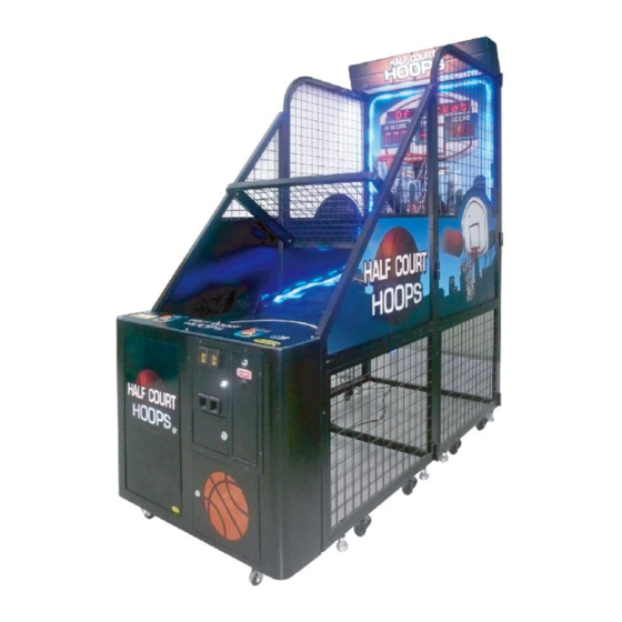
Operation Manual‘’ CONTENTS 1. Specifications ................3. 2. Package contents .................4. 3. Assembling instruction ..............6. 4. Intallation ..................19. 5. Package ..................21. 6. Game descripiton .................22. 7. Switches control signal ...............23 8. Parameter setting .................27 9. Game installation and service ............33 10. Game maintenance ...............34. 11. - Page 4 Operation Manual‘’ 1. Specifiactions: Rated power supply:AC220V±10 50Hz or 110V±10 60Hz (1) Power consumption:Min power consumption:90W Max power consumption:200W (2) Dimensions:W1030×D2200×H2243 (mm) (3) Weight:about 260Kg (4) Environment condition: (indoor)temperature :-10℃~+40℃ Humidity :≤90% Atmospheric pressure :86P ~106 P ※Note :Game parameters are subject change without notice.
-
Page 5: Package Contents
Operation Manual‘’ 2 Package contents 2.1 Make sure that all the parts shown below are included in the product package: : Part No. Name Illustartion R102-001-000 Main cabinet R102-002-000 Control panel R102-003-000 Header R102-004-000 Ball Gate Assy. R102-005-000 Playfield R102-006-000 Beam & back 1 R102-007-000 Beam &... - Page 6 Operation Manual‘’ 2.2 Spare parts 1: Part No. Name Spec. Illustration Note R102-810-000 Power cord 15A/220V 3.5m 5A/250(10A/125V) R102-429-000 Fuse φ5-20 R102-730-000 Manual English R102-423-000 R102-422-000 2222 R102-442-000 Bearing 6002Z GB/T894.2-1986/d R102-303-000 Circlip R102-443-000 Air pin R102-444-000 Basketball R102-445-000 Pump Hexagonal socket flat M8×25 BLK round head screw...
- Page 7 Operation Manual‘’ 3. Assemble instruction: 3.1 Assemble screws part list: Name Spec. Illustration Note Hexagonal socket flat M8×25 BLK round head screw Hexagonal socket flat M6×80 BLK round head screw Hexagonal socket flat M6×40 BLK round head screw Cross hexagon head M8×20 BLK kit bolt Cross hexagon head...
- Page 8 Operation Manual‘’ 3.2 Assemble steps: Open the package and take the main cabinet and other parts out Step 1...
- Page 9 Operation Manual‘’ Open the front bracket Step 2...
- Page 10 Operation Manual‘’ Install the beam and bracket 1 Install the beam and bracket 2 Install control panel fix board Step 3 Install contorl panel...
- Page 11 Operation Manual‘’ Those 4 bolts and nuts are needed in step 6. Please keep them. Remove bolts and take the front panel assembly. Step 4...
- Page 12 Operation Manual‘’ Install ball gate assembly Install playfield Step 5...
- Page 13 Operation Manual‘’ Install header assembly Step 6...
- Page 14 Operation Manual‘’ Install front panel Step 7 Fix control panel Step 7...
- Page 15 Operation Manual‘’ Fix side bracket Step 8...
- Page 16 Operation Manual‘’ 3.3 Layout on control panel: Control panel: High voltage exit Link wire “Link2” exit Link wire “Link 1” exit Low voltage exit Power cord exit Step 1:Connecting High voltage wires go through this hole. Low voltage wires through this hole.
- Page 17 Operation Manual‘’ 3.4 Link game: There are two buttons on the control panel: Link game button: Press this button to compete with others. Start button: Press this button to start the game. Link game schematic: ○ ○ How to link games:Connect Link 2 (in Game 1 ) to Link 1(in Game 2 ).
- Page 18 Operation Manual‘’ Notice : 1. When linking the game, there should be one game set as game #1. Any of the games can be set as game #1. The rest of the games can be #2 to #30 but you cannot repeat.
- Page 19 Operation Manual‘’ The extra Light Belt is wrapped with Nylon tape. 3.6 Connecting the power cord: Power box Power socket Power plug Power plug Power Notice Do not put heavy items on power cord. Do not touch the power plug with a wet hand. Do not draw or twist the cord.
- Page 20 Operation Manual‘’ 4. Installation: WARNING Indoor use only! 4.1 Locations to avoid installing: Warning This machine is designed for indoor use only. Never install this machine outdoors or any of the following: Places where dew may develop due to temperature differences; Locations close to hazardous article;...
-
Page 21: Package
Operation Manual‘’ 5. Package : For moving the game a short distance, just adjust the leveler and then move the game. For moving the game a long distance, it should be packed. Before operating the game, it should be assembled. Remove the control panel:... -
Page 22: Game Descripiton
Operation Manual‘’ Step 5:Pull the control panel in the front. Step 6:The package should be the same as the factory original packing. 6. Game Description: Insert coin(s). Press“single player”button or “link game” button to strat the game. Start shooting. The big display will show some relative information. The default setting is: points for stage 1. -
Page 23: Switches Control Signal
Operation Manual‘’ 7. Switches control signal 7.1 Refer to the attached I/O chart and the schematic. 7.2 To adjust DIP SWITCH, please refer the I/O chart. The initial setting is in capitalization. Main board:... - Page 24 Operation Manual‘’ 7.4 Main board connecting Test : Press “ test” to this mode, go into 0, press “test” after 1 second to go to 1. The oter is the same. Test 0:Jack number Led_J33 2-1 flash and display “-0” to Test 0. the rest will display LED numbers, Led J-33, Led –J-32 is c.
- Page 25 Operation Manual‘’ 7.5 Signal detections: Sensor detection board Sensor light: To detect if the rim is in the center or not. If the sensor detects the rim, it will light The rim is out of the position of the sensor. It can’t detect the signal so the light is off.
- Page 26 Operation Manual‘’ Relay board: Relay board sketch map: Ticket drive board: Ticket drive board sketch map: 7.7 DIP Setting(Default setting) Notice The above are subject change without notice.
-
Page 27: Parameter Setting
Operation Manual‘’ 8. Parameter Setting: (1) Coin per game: SW1-1 and SW1-2 are the switches to adjust how many coins to start the game. There are 4 options. DIP SW1 Item Content Note Free play 1 coin for one game Coin per game 2 coin for one game... - Page 28 Operation Manual‘’ (5) Round per game SW2- 1~ SW2-2 are the switches to adjust how many rounds for one play. There are 4 options. DIP SW2 Item Content Note 1 round for 1 game 2 round for 1 game Round per game 3 round for 1 game 4 round for 1 game...
- Page 29 Operation Manual‘’ (9)Score for pass SW3-1~ SW3-2 are the switches to adjust the score for passing each stage. There are 4 options. DIP SW3 Item Content Note Select project A Score for Select project B pass Select project C Select project D (10)JP score SW3-3~ SW3-4 are the switches to adjust the JP score.
- Page 30 Operation Manual‘’ (13)JP ticket SW3-8 is the switch to adjust if getting the JP ticket or not when you reach the JP score. There are 2 options.(It is enabled when using JP marquee) DIP SW1 Item Content Note Have JP ticket JP ticket No JP ticket JP (14)Game time, score for pass, 3 point time table.
- Page 31 Operation Manual‘’ NO 24 Game NO 25 NO 26 NO 27 NO 28 NO 29 NO 30 OFF OFF OFF OFF OFF Marquee 1 game as 1 group Group 5 game as 1 group 10 game as 1 group game 1 game as 1 group Demo Meter panel :...
-
Page 32: Game Installation And Service
Operation Manual‘’ 9. Game installation and service 9.1 Installation ○ Firstly check the assembling instructions and assemble the game. ○ Secondly, adjust the leveler of the game on even ground. ○ After installation, plug in. check the game operation. If there is a problem, stop the game and please check the trouble shooting section of this manual. - Page 33 Operation Manual‘’ 10. Game maintenance: Problem Cause Possible solution 1. No tickets in the game; 1. Refill and press reset button; 2. Take the jammed tickets out 2. Tickets are jammed; and then press the reset No ticket 3. Poor connection on the dispensed button;...
-
Page 34: Overall Structure
Operation Manual‘’ 11. Overall structure 11.1 Main part 1:... - Page 35 Operation Manual‘’ Part No. Name Spec. Note R102-003-000 Header Assy. R102-102-000 Rear frame_L Square tube R102-103-000 Rear frame_R Square tube R102-008-000 Motion Assy. R102-104-000 Rear side panel Square tube R102-105-000 Shield ring Square tube R102-106-000 Rear side panel Q235 R102-301-000 Shield ring Q235 R102-302-000...
- Page 36 Operation Manual‘’ 11.2 Main part 2...
- Page 37 Operation Manual‘’ Part No. Name Q’ty Spec. Note R102-111-000 Rear frame rack Square tube R102-112-000 Rear side_R net Q235 R102-113-000 Front frame Q235 R102-114-000 Front net Q235 R102-115-000 Front side_R rack Square tube R102-116-000 Beam rack 2 Q235 R102-117-000 Beam 2 Square tube R102-118-000 Beam rack 1...
- Page 38 Operation Manual‘’ 11.3 Motion Assy.
- Page 39 Operation Manual‘’ Part No. note Name Q’ty Spec. R102-405-000 φ20 R102-503-000 Back board 15mm R102-126-000 Bearing rack 3 mm R102-303-000 Shield ring R102-304-000 Bearing axis R102-127-000 Bearing track 1.5 mm R102-128-000 Sensor rack 1.5 mm R102-129-000 Reinforce_L R102-130-000 Reinforce_R R102-131-000 Attached board 1.5 mm R102-132-000...
- Page 40 Operation Manual‘’ 11.4 Ball gate Assy...
- Page 41 Operation Manual‘’ Part No. Name Q’ty Spec. Note R102-143-000 Ball 1.5mm R102-144-000 Hinge R102-504-000 Bed plate 15mm R102-145-000 Fix board R102-411-000 Motor YN60-6Z/60JB100G10 R102-412-000 Capacito Motor R102-146-000 bracket Encoder R102-147-000 wheel R102-148-000 Connection R102-305-000 Axle sleeve R102-306-000 Shield ring R102-413-000 Sensor NC(YIIN-5V) 11.5 Control panel Assy.
- Page 42 Operation Manual‘’ Part No. Name Spec. Note R102-414-000 Bulb 12V 3W R102-415-000 Coin mech R102-416-000 Coin SW ZIPPYCNR-055-03-Z R102-417-000 Bulb clamp For coin lamp R102-418-000 Counter R102-419-000 Test button 1 RED ,1GRN,1 BLK R102-420-000 Dual POT R102-421-000 Single POT R102-149-000 Coin box R102-422-000 Coin box lock...
- Page 43 Operation Manual‘’ 11.6 Other electroinc component:...
- Page 44 Operation Manual‘’ Part No. Name Q’ty Spec. Note R102-805-000 Dot matrix DZ-1120.PCB R102-806-000 2 Digit display LED86*65-2U.PCB R102-807-000 3 Digit display LED86*65-3U.PCB R102-432-000 Sensor Fanse.PCB R102-433-000 Fuorescent lamp1 T5 14W R102-434-000 Insulated cable φ50 Caliberφ50 R102-435-000 Insulated cable φ24 Caliber φ24 R102-808-000 3 Core connector 1 male ,1 female...
- Page 45 Operation Manual‘’ 11.7 Game decal:...
- Page 46 Operation Manual‘’...
- Page 47 Operation Manual‘’ NAME Spec. QTY(pcs) PART NO. JTQS-HM-01 Rear side-L decal 810×622(PVC) JTQS-HM-02 Rear side-R decal 810×622(PVC) JTQS-HM-03 Front side-L decal 804×464(PVC) JTQS-HM-04 Front side-R decal 804×464 (PVC) JTQS-HM-05 Playfield 1 930×560(δ0.3 PVC) JTQS-HM-06 Playfield 2 930×582(δ0.3 PVC) JTQS-HM-07 Playfield 3 928×705(δ0.3 PVC)...
Need help?
Do you have a question about the Half Court Hoops and is the answer not in the manual?
Questions and answers