Advertisement
Quick Links
OWNER'S
MANUAL
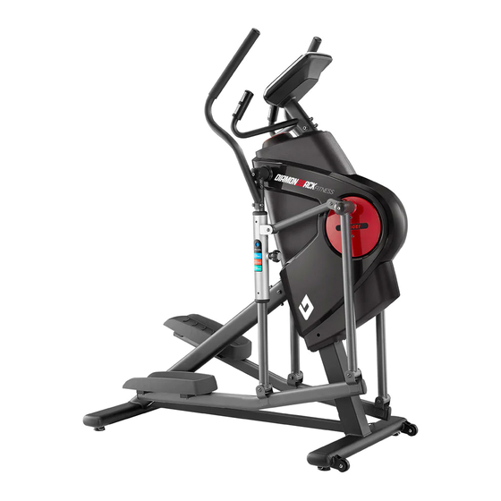
Product May Vary Slightly From Picture
MADE IN TAIWAN
Excessive
Exercise can present a health risk. Consult a physician before beginning any
exercise program with this equipment.
If you feel faint or dizzy, immediately discontinue use of this equipment. Serious bodily injury
can occur if this equipment is not assembled and used correctly. Serious bodily injury can also
occur if all instructions are not followed.
Keep children and pets away from equipment when in use. Always make sure all bolts and
nuts are tightened prior to each use. Follow all safety instructions in this manual.
CAUTION: WEIGHT ON THIS PRODUCT SHOULD NOT EXCEED 136KG / 300LBS.
v.
III-1K
Advertisement

Related Manuals for Diamondback 1060Ef


Summary of Contents for Diamondback 1060Ef
- Page 1 OWNER’S MANUAL Product May Vary Slightly From Picture MADE IN TAIWAN Excessive Exercise can present a health risk. Consult a physician before beginning any exercise program with this equipment. If you feel faint or dizzy, immediately discontinue use of this equipment. Serious bodily injury can occur if this equipment is not assembled and used correctly.
- Page 2 This trend continues today, as the strong Diamondback brand resonates with both the boomers who grew up with the bicycles, as well as the younger generations riding them today.
-
Page 3: Elliptical Trainer
“S AFETY NSTRUCTION” WARNING: To reduce the risk of serious injury, read the following safety instructions before using the ELLIPTICAL TRAINER 1. Read all warnings posted on the equipment 2. Read this Owner's Manual and follow it carefully before using the equipment. Make sure that it is properly assembled and tightened before use 3. - Page 4 “A SSEMBLY ARTS” Unpack the box in a clear area. Follow the List of Assembly Parts below to check and make sure all assembly parts are present and in good condition. Do not dispose of the packing material until the assembly process is completed. Assembly tools and hardware kit have included for you to use when assembling the product Console Fixed Handlebar...
- Page 5 “H ARDWARE DENTIFICATION HART” Unpack the box in a clear area. Follow the List of Hardware Kit below. This chart is provided to help identify the hardware used in the assembly process. Place the washers, the end of bolts, or screws on the circles to check for the correct diameter.
- Page 6 “B EFORE EGIN” Thank you for choosing the Elliptical Trainer. We Too often, our busy lifestyles limit our time and take great pride in producing this quality product and opportunity to exercise. The equipment provides a hope it will provide many hours of quality exercise to convenient and simple method to begin your assault make you feel better, look better and enjoy life to its on getting your body in shape and achieving a...
- Page 7 “A SSEMBLE NSTRUCTIONS” Detailed Lever- drawing 1 Stabilizer Adjustment Plate Leveler (27) Detailed Lever- drawing 2 Stabilizer Adjustment Plate Leveler (27) Adjustment – TEP 1 Leveler Assembly Plate a. Follow the drawings to attach 2pcs Levelers (27) Leveler (27) under the Front Stabilizer (28). Be sure to tighten the Levelers (27) securely until screw lines are eliminated as the drawing 1 shown on the top right corner.
- Page 8 “A SSEMBLE NSTRUCTIONS” – TEP 3 Rear Stabilizer Assembly a. Refer to below, attach 2pcs Levelers (27) under the Rear Stabilizer (25) and make sure they will level on the floor. NOTE: Refer to left, 5pcs Washers (8x16x2.0t)(66), 5pcs Lock Washers (M8)(65), 5pcs Bolts, Button Head (M8xp1.25x16mm)(87) have preassembled on the rear of the Main Frame (1).
- Page 9 “A SSEMBLE NSTRUCTIONS” – TEP 4 Support Tube Assembly a. Refer to left, attach the Support Tube (30) to the Main Frame (1) by slightly attaching 1pcs Bolt, Socket Head (M8xp1.25x20mm)(85), 1pcs Lock Washer (M8)(65), 1pcs Washer (8x16x2.0t)(66). NOTE: Please do not fully tighten the Bolt (85) until part a of Step 5.
- Page 10 “A SSEMBLE NSTRUCTIONS” – TEP 5 Bolt Tightening Assembly a. Refer above two photos to go back to the bottom of the Support Tube (30) to fully tighten 2pcs Socket Bolts (85), 2pcs Lock Washers (65) and 2pcs Washers (66). b.
- Page 11 “A SSEMBLE NSTRUCTIONS” – TEP 6 Swing Arm Assembly a. There is a “R” & “L” decal on the Swing Arm (36). b. Refer to left, gently remove plastic packaging material from two Axles. NOTE: Be sure not to remove the washers that already installed inside while removing packaging material...
- Page 12 – TEP 7 Pivoting Arm & Crank Linkage Assembly a. There is a “R” & “L” decal on the Pivoting Arm (48). b. 2pcs Bolts, Socket Head (M8×p1.25×65mm)(88) and 2pcs Nylon Nuts (M8xp1.25)(75) have preassembled into the Pivoting Arm (48). c.Remove the above bolts and nuts for following assembly process.
- Page 13 “A SSEMBLE NSTRUCTIONS” – TEP 8 Pedal Support Arm Assembly NOTE: Refer above, 4pcs Thin Nylon Nut (M8xp1.25)(74), 4pcs Bolts, Socket Head (M8xp1.25x75mm)(89) have preassembled on the Pedal Support Arm (58). a. Remove above bolts and nuts from the Pedal Support Arm (58). b.
-
Page 14: Fixed Handlebar
“A SSEMBLE NSTRUCTIONS” – TEP 10 Fixed Handlebar Assembly NOTE: Refer to left, 4pcs Washers (8x16x2.0t)(66), 4pcs Lock Washers (M8)(65), 2pcs Bolts, Socket Head (M8xp1.25x16mm)(84), 2pcs Bolts, Socket Head (M8xp1.25x30mm)(86) have preassembled on the Main Frame (1). a. Remove the above bolts, washers from the Main Frame (1) for following assembly. - Page 15 “A SSEMBLE NSTRUCTIONS” – TEP 11 Console Assembly FIG 1 Hole A Hole A NOTE: Refer to the drawing above. To assemble console on correct position, firstly secure the right bottom corner of the console to Hole A with Bolt (82).
- Page 16 “A SSEMBLE NSTRUCTIONS” – TEP 12 Upper Handlebar Assembly a. There is a “R” & “L” decal on the Upper Handlebar (44, 45). b. NOTE: 2pcs Bolts, Button Head (M8×p1.25×16mm)(87) and 2pcs Lock Washers (M8)(65) and 2pcs Washers (8x16x2.0t)(66) have preassembled into the Pivoting Arm (48). c.Remove the above bolts and washers from the Pivoting Arm (48).
- Page 17 “O PERATION NSTRUCTIONS” OW TO MOVE THE ITEM SAFELY Hold the Rear Stabilizer (25) up with two hands and tow the item to the desired place carefully. Make sure the floor is level while towing the item. OW TO ADJUST THE STRIDE LENGTH The Elliptical Trainer is quipped with three adjustable stride lengths from 18’’...
- Page 18 “ ” ONSOLE NSTRUCTIONS ake a few minutes to review the console layout. Below is an overview of the console’s features and functions e recommend that you use the console to help vary your workout routine and keep you focused on your process toward your fitness goals.
- Page 19 “C NSTRUCTIONS – ” ONSOLE ONSOLE UTTONS onsole uttons START/PAUSE a. Press to begin your exercise START/PAUSE b. Press again to stop and pause all functions during your exercise program. All the date on the display will then freeze. START/PAUSE c.
- Page 20 “C NSTRUCTIONS – ” ONSOLE ONSOLE UTTONS START/ PAUSE MODE During workout (after pressing ), the user could press to select SPEED, DISTANCE and CALORIES, or RPM, ODO (Odometer) and WATT RPM, ODO, WATT will show at the same time SPEED, DISTANCE, CAL.
- Page 21 “C ONSOLE NSTRUCTIONS”– ONSOLE UNCTIONS” onsole unctions PROGRAM: The console comes with 16 preset programs Displays programs for selection during setup, from P1 ~ P16 Displays the selected program during exercise LEVEL: Displays torque/resistance level of the current program, from 1 to 16 torque/resistance level;...
- Page 22 “C ONSOLE NSTRUCTIONS”– ONSOLE UNCTIONS” onsole unctions CALORIES: Count Up: If target calories were not selected, this measures total calories your body burned during exercise Count Down: If you have set the preference value of calories, the console will count down from that selected target calories down to 0 BMR: ...
- Page 23 “C NSTRUCTIONS – ONSOLE ANUAL ROGRAM (P1)” “1” Prior information: Press any button on the console or begin pedaling to turn on the console a. Make sure that the power cord is properly plugged into the socket. b. The console would automatically shut off after 4 minutes of inactivity c.
- Page 24 “C NSTRUCTIONS – ONSOLE ANUAL ROGRAM (P1)” “B. SET THE DESIRED TIME or DESIRED DISTANCE To avoid the user to select TIME and DISTANCE in the same program to confuse the user couldn’t distinguish which one (TIME or DISTANCE) as the first priority. User could only select TIME or DISTANCE in the same program, one at the time If you would like to select TIME value, not DISTANCE If you would like to select DISTANCE value, not TIME...
- Page 25 “C NSTRUCTIONS – ONSOLE ANUAL ROGRAM (P1)” “D. START EXERCISE” to begin exercise. “START” would then appear on the screen START/ PAUSE START/ PAUSE button: Press “ E. DURING WORKOUT, ALWAYS MONITOR YOUR CURRENT HEART RATE STATUS” NOTE for HEART RATE: ...
- Page 26 “C NSTRUCTIONS – ONSOLE ROGRAM (P2 ~ P7)” “1” Prior information: ”HOLD TO RESET” button, an easy way to reset and enter into POWER ON status START/PAUSE Continue pressing a few seconds, all the date will reset to the initial value and the console will return to POWER ON status POWER ON status “2”...
- Page 27 “C NSTRUCTIONS – ONSOLE ROGRAM (P2 ~ P7)” “B. SET THE DESIRED TIME or DESIRED DISTANCE To avoid the user to select TIME and DISTANCE in the same program to confuse the user couldn’t distinguish which one (TIME or DISTANCE) as the first priority. User could only select TIME or DISTANCE in the same program, one at the time If you would like to select TIME value, not DISTANCE If you would like to select DISTANCE value, not TIME...
- Page 28 “C NSTRUCTIONS – ONSOLE ROGRAM (P2 ~ P7)” “D. START EXERCISE” to begin exercise. “START” would then appear on the screen START/ PAUSE START/ PAUSE button: Press “ E. DURING WORKOUT, ALWAYS MONITOR YOUR CURRENT HEART RATE STATUS” NOTE for HEART RATE: ...
- Page 29 “C NSTRUCTIONS – ONSOLE ROGRAM (P8)” “1” Prior information: ”HOLD TO RESET” button, an easy way to reset and enter into POWER ON status START/PAUSE Continue pressing a few seconds, all the date will reset to the initial value and the console will return to POWER ON status POWER ON status “2”...
- Page 30 “C NSTRUCTIONS – ONSOLE ROGRAM (P8)” 3. ENTER UP or DOWN button and then button: ENTER c. Press button to confirm your HEIGHT value and enter the mode to set your WEIGHT. UP or DOWN d. Use buttons to set your WEIGHT (10 ~ 200KG; 0.2 KG INCREMENT / 23 ~ 440 LBS;...
- Page 31 “C NSTRUCTIONS – ONSOLE ROGRAM (P8)” 3. BODY FAT%: You body fat percentage is simply the percentage of fat your body contains. If you are 150 pounds and 10% fat, it means that your body consists of 15 pounds fat and 135 pounds lean body mass, such as bone, muscle, organ tissue, blood and everything else.
- Page 32 “C NSTRUCTIONS – ONSOLE ROGRAM (P9 ~ P12)” T.H.R. 60% H.R.C. 75% H.R.C. 85% H.R.C. “1” Prior information: ”HOLD TO RESET” button, an easy way to reset and enter into POWER ON status START/PAUSE Continue pressing a few seconds, all the date will reset to the initial value and the console will return to POWER ON status POWER ON status “2”...
- Page 33 “C NSTRUCTIONS – ONSOLE ROGRAM (P9 ~ P12)” B. SET THE DESIRED TIME or DESIRED DISTANCE To avoid the user to select TIME and DISTANCE in the same program to confuse the user couldn’t distinguish which one (TIME or DISTANCE) as the first priority. User could only select TIME or DISTANCE in the same program, one at the time If you would like to select TIME value, not DISTANCE If you would like to select DISTANCE value, not TIME...
- Page 34 “C NSTRUCTIONS – ONSOLE ROGRAM (P9 ~ P12)” E. MUST-KNOWN HEART RATE PROGRAM INFO.” a. SIMPLE FORMULA OVERVIEW: BEGINNER: 60% of maximum heart rate; 60% of (220 – you age) TRAINER: 75% of maximum heart rate; 75% of (220 – you age) ACTIVE TRAINER: 85% of maximum heart rate;...
- Page 35 “C NSTRUCTIONS – ONSOLE ETTING ROGRAM (P13 ~ P16)” Prior information: ”HOLD TO RESET” button, an easy way to reset and enter into 1” POWER ON status START/PAUSE Continue pressing a few seconds, all the date will reset to the initial value and the console will return to POWER ON status POWER ON status “2”...
- Page 36 “C NSTRUCTIONS – ONSOLE ETTING ROGRAM (P13 ~ P16)” B. SET THE DESIRED TIME or DESIRED DISTANCE To avoid the user to select TIME and DISTANCE in the same program to confuse the user couldn’t distinguish which one (TIME or DISTANCE) as the first priority. User could only select TIME or DISTANCE in the same program, one at the time If you would like to select DISTANCE value, not TIME If you would like to select TIME value, not DISTANCE...
- Page 37 “C NSTRUCTIONS – ONSOLE ETTING ROGRAM (P13 ~ P16)” “E. SET THE TORQUE/RESISTANCE LEVEL” ENTER UP or DOWN button and then button: a. The USER SETTING PROGRAM allows the user to manually set the torque/resistance level, the console will divide the time into 10 intervals. The user could through their preference to set the desired torque/resistance level in each time interval ENTER b.
- Page 38 “C “ ONSOLE ROUBLE HOOTING UIDE PROBLEM POSSIBLE CAUSE SOLUTION 1. Motor Malfunction Replace Motor 2. Magnetic System Replace Magnetic System/Flywheel Malfunction or got stuck No Motor signal 3. Connection Wires are not Check whether the wires are well-connected or well-connected or broken replace the broke wires with the new wires 4.
- Page 39 “C “ ONSOLE ROUBLE HOOTING UIDE PROBLEM POSSIBLE CAUSE SOLUTION Verify the gap between Speed Sensor and the Magnet is 5mm or less The Computer isn’t receiving a signal Verify that all the Wire Plugs are connected FIRMLY, correctly and are not from the Speed damaged The Speed...
- Page 40 “C ONDITIONING UIDELINES” How you begin your exercise program depends on your physical condition. If you have been inactive for several years, or are severely overweight, you must slowly and increase your time on the item gradually: a few minutes per workout. Initially, you may be able to exercise only for a few minutes in your target zone, however, your aerobic fitness will improve over the next six to eight weeks.
- Page 41 “W ARM- P AND OOL- OWN” Warm-up The purpose of warming up is to prepare your body for exercise and to minimize injuries. Warm up for two to five minutes before strength-training or aerobic exercising. Perform activities that raise your heart rate and warm the working muscles.
- Page 42 “P RODUCT ARTS RAWING (A)”...
- Page 43 “P RODUCT ARTS RAWING (B)”...
- Page 44 “P IST” NO. Item Name Q'TY NO. Item Name Q'TY Main Frame Bearing (6201) Spacer (8x14x40mm) for Telescoping Tension Bracket Eye Bolt Crank Linkage Bearing (6000) Spacer (8x14x28mm) for Crank Linkage Pulley (120-42mm) Handheld Plug Belt (1092J6) Foam Grip for Upper Handlebar Spacer (10x14x32mm) Left Upper Handlebar Crank...
- Page 45 “P IST” NO. Item Name Q'TY Nylon Nut (M6xp1.0) Thin Nylon Nut (M8xp1.25) Nylon Nut (M8×p1.25) Nylon Nut (M10×p1.5) Bolt (M6×p1.0×12mm) Bolt (L=30mm) Screw (M4×20mm) Screw (M5×20mm) Screw (M3×p0.5×16mm) Screw (M5×p0.8×15mm) Bolt (M6×p1.0×12mm) Bolt (M8×p1.25×16mm) Bolt (M8×p1.25×20mm) Bolt (M8×p1.25×30mm) Bolt (M8×p1.25×16mm) Bolt (M8×p1.25×65mm) Bolt (M8×p1.25×75mm) Bolt (M8×p1.25×15mm)
Need help?
Do you have a question about the 1060Ef and is the answer not in the manual?
Questions and answers
what is the cord adapter for this model 1060EF
The power adapter for the Diamondback 1060 EF is described as a power brick. It connects to the lower left-hand side on the front stabilizer bar of the equipment.
This answer is automatically generated
My machine is sliding from left to right when I use it. Its where the pedal arms meet the red circle. How can this be fized?