Radwin 1000 User Manual
Broadband wireless transmission system
Hide thumbs
Also See for 1000:
- User manual (348 pages) ,
- User manual and installation manual (174 pages) ,
- Installation and operation manual (97 pages)

Related Manuals for Radwin 1000


Summary of Contents for Radwin 1000
- Page 1 RADWIN 1000/2000/5000 Broadband Wireless Transmission System User Manual Version 2.5.30p3 UM 5000-2530/04.11...
-
Page 2: Notice
RADWIN protected under international copyright law and shall be and remain solely with RADWIN. The RADWIN name is a registered trademark of RADWIN Ltd. No right, license, or interest to such trademark is granted hereunder, and you agree that no such right, license, or interest shall be asserted by you with respect to such trademark. -
Page 3: Radwin Worldwide Offices
China Sales Office Asian Games Village Huiyuan Gongyu J1312 Beijing 100101 China Tel: +86 010 8498 0629 For technical support contact: support@radwin.com For technical support in India only, contact: support-india@radwnin.com For sales support contact: sales@radwin.com Website: www.radwin.com RADWIN 1000/2000/5000 User ManualVersion 2.5.30p3... -
Page 4: Regulatory Compliance
Changes or modifications to this equipment not expressly approved by the party responsible for compliance (RADWIN Ltd.) could void the user's authority to operate the equipment. It is the responsibility of the installer to ensure that when using the outdoor antenna kits in the United States (or where FCC rules apply), only those antennas certified with the product are used. - Page 5 780 should be considered in addition to NEC. 3. For Canada, appropriate requirements of Section 60 of the CEC 22.1should be considered as applicable. 4. E1/T1 ports are intended for connection to indoor lines only and are not exposed to outdoor plants. RADWIN 1000/2000/5000 User ManualVersion 2.5.30p3...
-
Page 6: Table Of Contents
Welcome! ......................1-1 Key Applications ..................... 1-2 WiMAX and IP Backhaul................1-2 Broadband Access ..................1-2 Private Networks ..................1-3 Key Features of RADWIN 1000/2000/5000 ............... 1-3 RADWIN 1000/2000/5000 Link ................1-5 The Radio Outdoor Unit (ODU) ..............1-6 The Indoor Units (IDU) ................1-8 IDU-C......................... 1-8 IDU-E ......................... - Page 7 Installing the Link: Step 6, Installation Summary and Exit ........4-26 Chapter 5 Configuring the Link Link Configuration: Getting Started ................5-1 The Main Window of the RADWIN Manager ..........5-1 The RADWIN Manager Toolbar ..............5-2 The RADWIN Manager Main Menu..............5-3 Elements of the RADWIN Manager Main Window ........5-6...
- Page 8 Appendix A Technical Specifications Configuration ......................A-1 Radio ........................A-2 Ethernet Interface ....................A-4 Management......................A-5 Mechanical......................A-5 Power........................A-5 Environmental....................... A-5 Safety........................A-5 EMC ........................A-5 Air Interface......................A-5 Appendix B Wiring Specifications ODU-IDU Cable ..................... B-1 RADWIN 1000/2000/5000 User ManualVersion 2.5.30p3...
- Page 9 IDU-C Alarm Connector ................B-3 Appendix C Pole and Wall Installation ODU Mounting Kit Contents..................C-1 Mounting RADWIN 1000/2000/5000 on a pole............C-2 Mounting RADWIN 1000/2000/5000 on a Wall............C-3 Mounting an External Antenna ................C-3 Appendix D Link Budget Calculator Overview ......................
- Page 10 Contenu du kit de montage ODU ..............I-4 Montage sur un pylône ................I-5 Montage sur un mur..................I-6 Montage d'une antenne externe ..............I-7 Contenu du kit de montage d'une antenne externe ........I-7 Index RADWIN 1000/2000/5000 User ManualVersion 2.5.30p3...
- Page 11 HANNEL ETTINGS WITHOUT AUTOMATIC CHANNEL SELECTION 5-8 C .................5-16 IGURE HANNEL FREQUENCY OPTIONS 5-9 C “O ” O ........5-17 IGURE HOOSING AN THER PERATING HANNEL FREQUENCY 5-10 T ..........5-18 IGURE RANSMISSION OWER AND NTENNA ARAMETERS RADWIN 1000/2000/5000 User ManualVersion 2.5.30p3...
- Page 12 URGE UPPRESSOR AND GROUNDING AT BUILDING ENTRY POINT F-1 T MIB............F-3 IGURE EVEL ECTIONS OF THE PRIVATE I-4 M ................. I-5 IGURE ONTAGE SUR UN PYLÔNE I-5 M ..................I-6 IGURE ONTAGE SUR UN MUR RADWIN 1000/2000/5000 User ManualVersion 2.5.30p3...
- Page 13 ATERIALS MOUNTING KIT F-1 S RFC 1213 V ...............F-4 ABLE UPPORTED ARIABLES F-2 P MIB P .................F-5 ABLE RIVATE ARAMETERS F-3 MIB T ....................F-18 ABLE RAPS G-1 O .................. G-1 ABLE UTPUT LARMS INOUT RADWIN 1000/2000/5000 User ManualVersion 2.5.30p3...
-
Page 14: Chapter 1 Introduction
• High Tx power The RADWIN 1000/2000 radio series supports the 2.4, 4.9, 5.3, 5.4 and 5.8 GHz spectrum bands, and complies with international standards and regula- tions (FCC, IC Canada). The 5.8 GHz spectrum band complies with FCC rule 47 CFR Part 15 subparts C and E. -
Page 15: Key Applications
The model RADWIN 1000 RW-1020-0150 / RADWIN 2000 RW-2020-0150 supports the 2.4GHz band and complies with FCC and IC standards. The RADWIN 1000 3GHz Band / RADWIN 2000 3GHz Band / RADWIN 5000 3GHz Band support the 3.5 and 3.65 GHz spectrum bands and comply with FCC and IC standards. -
Page 16: Private Networks
Chapter 1 Figure 1-2: Typical Broadband Access application Private Networks RADWIN 1000/2000/5000 is the ultimate solution for private networks such as enterprises, education, government and utility organizations that wish to own and manage their own networks and eliminate the costly recurring charges from service providers. - Page 17 Chapter 1 Built on advanced MIMO and OFDM technologies, the RADWIN 1000/2000 system provides a high-capacity link at channel band- width of 40MHz. This channel bandwidth supports high robustness of the air interface under interference and harsh conditions. In coun- tries where applicable, narrow channel bandwidth reduces the cost of the spectrum license.
-
Page 18: Radwin 1000/2000/5000 Link
RADWIN 1000/2000/5000 Link Chapter 1 The RADWIN Manager application has full local and remote manage- ment capabilities. The user-friendly SNMP based management tool provides full end-to-end configuration, event logging, and perfor- mance monitoring capabilities. Enhanced Security The security features of RADWIN 1000/2000/5000 include: •... -
Page 19: The Radio Outdoor Unit (Odu)
Figure 1-4: Example of Link Architecture - System Components The Radio Outdoor Unit (ODU) The ODU is the radio transceiver of the RADWIN 1000/2000/5000 system. It supports two radios for MIMO operation. It is available with an integrated antenna (Integrated Antenna ODU) or with connectors for an external antenna (Connectorized ODU). - Page 20 23dBi. The ODU contains both the radio and the antenna as a single unit housed in a weatherproof case. • Connectorized ODU This ODU has 2x N-type connectors for connecting an external antenna. RADWIN 1000/2000/5000 User ManualVersion 2.5.30p3...
-
Page 21: The Indoor Units (Idu)
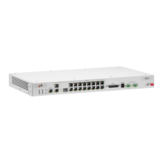
The IDU-C is designed to be rack mounted. One IDU-C product is available in release 2.5.30p3: Table 1-2: Release 2.1 IDU-C Products Ethernet Form Part Number Power ports factor Dual DC feed 7200-2000 19" 1U -20 to -60VDC RADWIN 1000/2000/5000 User ManualVersion 2.5.30p3... -
Page 22: Idu-E
Power Over Ethernet (PoE) Devices The PoE device provides Ethernet service only, with power for the ODU. The PoE device is extremely compact, having only two Ethernet ports and a standard 3 pin male AC power socket. RADWIN 1000/2000/5000 User ManualVersion 2.5.30p3... -
Page 23: Antennas
The antenna gain and transmitting power may be limited by country regula- tions. The RADWIN 1000/2000/5000 may be operated with an integrated antenna that is part of the ODU unit, or with external antennas connected to the ODU via N-type connectors. All cables and connections must be connected correctly to reduce RF losses. -
Page 24: Flat Panel Antennas
RF feeder cables that produce 6 dBi mi-nimal assembly gain. The RADWIN 1000 3GHz Band / RADWIN 2000 3GHz Band / RADWIN 5000 3GHz Band operating in the 3.5 and 3.65 GHz can utilize external antennas with RF feeder cables that produce 13.5 dBi minimal assembly gain. -
Page 25: Parabolic Dish Antennas
IP address. It can also manage each side of the link separately. The RADWIN Manager application facilitates installation and configuration of the link between the ODU units. The intuitive, easy-to-use RADWIN Man- ager has a graphical Microsoft Windows interface, and can be run locally and remotely. -
Page 26: Accessories
Accessories Chapter 1 Figure 1-13: RADWIN Manager screen Accessories RADWIN provides a variety of accessories to support the RADWIN 1000/ 2000/5000 system: • PoE devices • AC Power Adaptor • External Lightning Protection Unit • Cables to connect the various system elements... -
Page 27: How To Use This Manual
How to Use this Manual Chapter 1 How to Use this Manual This User Manual is divided into functionally distinct chapters reflecting the activities required to set up a RADWIN 1000/2000/5000. The division is shown in the following table: Chapter/ Subject... - Page 28 A. (The precise requirements for the managing computer are set out in chapter 3, Hardware Installation). RADWIN 1000/2000/5000 supports three connection methods for the man- aging computer: • Local - a direct peer to peer connection between the Ethernet ports on the managing computer and the IDU or PoE device.
-
Page 29: Conventions Used In This Manual
• Draw your attention to something that may not be obvious or coun- Note ter-intuitive • Emphasize a special feature or peculiarity of the RADWIN 1000/2000/ 5000 • Offer an external reference for additional information • Add a caveat that would not qualify as a full Caution or Warning (see below) •... -
Page 30: Windows Terminology
If you click Site A or Site B in the tool bar, you will be offered another win- dow, which in turn displays on of several panels depending on which func- tion you choose. RADWIN 1000/2000/5000 User ManualVersion 2.5.30p3 1-17... -
Page 31: Figure 1-14 Sitec
Windows Terminology Chapter 1 Figure 1-14: Site Configuration window with open Management panel RADWIN 1000/2000/5000 User ManualVersion 2.5.30p3 1-18... -
Page 32: Chapter 2 Site Preparation
1. Preliminary survey - The proposed link is analyzed in the office using a topographic map. 2. Physical survey - The locations of the RADWIN 1000/2000/5000 indoor and outdoor equipment are determined on-site. 3. Radio Frequency (RF) survey - It is recommended that the installation... -
Page 33: Stage 1: Preliminary Survey
2. Measure the distance between the sites; check that it is within the speci- fied range of the RADWIN 1000/2000/5000. 3. On the urban map, check for developed areas situated between the two installation sites. Pay attention to these areas when performing the phys- ical site survey;... -
Page 34: Stage 2: Physical Survey
Stage 2: Physical Survey Chapter 2 7. If the site chosen does not meet requirements, consider alternative sites. 8. Use the Link Budget Calculator (on the CD supplied with the RADWIN 1000/2000/5000 or using the RADWIN Manager) to determine the expected performance. -
Page 35: Additional Outdoor Site Requirements
Allow 2-4 hours duration for a good RF survey. It is possible to install the RADWIN 1000/2000/5000 link and use the RADWIN Manager to find a clear channel. Each frequency channel can be evaluated in turn. Achievement of a clear channel is indicated by the Quality... -
Page 36: Chapter 3 Hardware Installation
Warning government regulatory authorities. Failure to do so may expose the end user or the service provider to legal and financial liabilities. RADWIN and its resellers or distributors are not liable for injury, damage or violation of regulations associated with the installation of outdoor units or antennas. -
Page 37: Protection Against Lightning
The use of lightning protection is dependent on regulatory and end user requirements. All of RADWIN outdoor units are designed with surge limiting circuits to minimize the risk of damage due to lightning strikes. RADWIN recommends the use of additional surge arrestor devices to protect the equipment from nearby lightning strikes. -
Page 38: Figure 3-2 Connectorized Odu - F
The label is self-adhesive. You should keep this label safe • Cable glands (to be used with the ODU-IDU cable) Figure 3-1: ODU Mounting kit ODU - Front View ODU - Rear View Figure 3-2: Connectorized ODU - Front and rear views RADWIN 1000/2000/5000 User ManualVersion 2.5.30p3... -
Page 39: Idu Package Contents
• Two DC power plugs for power cables - see figure 3-5 below Figure 3-4: IDU-C Package contents - the IDU-C Figure 3-5: IDU-C Package contents - the mounting kit and DC power plugs RADWIN 1000/2000/5000 User ManualVersion 2.5.30p3... -
Page 40: External Antenna Package Contents
• IDU grounding cable 18AWG • ODU-IDU cable (outdoor class, CAT-5e, 4 twisted pairs, 24AWG) Hardware Installation Sequence The following steps are required to install the RADWIN 1000/2000/5000 system: 1. Mounting the ODUs, page page 3-6. 2. Mounting the external antennas (if used), page page 3-7. -
Page 41: Outdoor Installation
ODU. A mast-sited ODU typically uses a pole attached to the mast. Note A RADWIN 1000/2000/5000 link operates in pairs of two ODUs with the same configuration. Both ODUs must be installed, and the antennas aligned for maximum throughput. -
Page 42: Mounting External Antennas
Mounting the Lightning Protection Devices The use of lightning protection is dependent on regulatory and end user requirements. The RADWIN 1000/2000/5000 ODU is designed with surge limiting circuits to minimize the risk of damage due to lightning strikes. RADWIN 1000/2000/5000 User ManualVersion 2.5.30p3... -
Page 43: Outdoor Connections
AC/DC adapter. Figure 3-7: New style IDU-E: Rear panel Mounting the IDU-C The RADWIN 1000/2000/5000 IDUs are all rack mounted, as shown in figure 1-6. A front panel keyed schematic of a rack mounted IDU-C is... - Page 44 Mounting the IDU-C Chapter 3 Figure 3-8: IDU-C front panel figure 3-9 we display a perspective view of the IDU-C: Figure 3-9: IDU-C - A perspective view RADWIN 1000/2000/5000 User ManualVersion 2.5.30p3...
- Page 45 Grounding Lug Use the lug supplied Rack mounting holes Detachable Rack mounting brackets The Indicator LEDs (Item A in table 3-1 above) are shown in more detail in figure 3-10 below: Figure 3-10: IDU-C LEDs RADWIN 1000/2000/5000 User ManualVersion 2.5.30p3 3-10...
-
Page 46: Connecting Power To The Idu
Note Connecting power to the IDU The IDU-C has redundant power connection circuits (items G and H in figure 3-8 above). An enlarged schematic of the power connectors is shown in below: RADWIN 1000/2000/5000 User ManualVersion 2.5.30p3 3-11... -
Page 47: Connecting The Odu To The Idu
Connecting User Equipment To connect user equipment to the IDU: • Connect user switch/router or any other compatible device to the IDU panel RJ-45 ports designated LAN (see item C in figure 3-8 above). RADWIN 1000/2000/5000 User ManualVersion 2.5.30p3 3-12... -
Page 48: Connecting And Aligning Odus / Antennas
Connecting and Aligning ODUs / Antennas You perform antenna alignment using the ODU's audible tone. To speed up the installation time, alignment of a RADWIN 1000/2000/5000 system should be performed by two teams simultaneously, at site A and at site B. -
Page 49: Figure 3-12 Beeps
3 to 7 above to align the second antenna. 4. Secure the antennas to the pole/wall. 5. Restore one of the antennas to ANT 2 on both sides of the link. RADWIN 1000/2000/5000 User ManualVersion 2.5.30p3 3-14... -
Page 50: Chapter 4 Link Installation: The Radwin Manager
Chapter 4 Link Installation: The RADWIN Manager This chapter explains how to use the RADWIN Manager to install a radio link. Installing theRADWIN Manager Application Minimum System Requirements The RADWIN Manager application is distributed on a CD. Operating system specific PC resources required by the application are set out in... -
Page 51: Starting The Radwin Manager
Starting the RADWIN Manager Chapter 4 2. Choose Install RADWIN Manager and follow the on-screen instructions of the installation wizard to complete the setup of the RADWIN Manager application. If the installation program fails to start, browse to your CD/DVD drive, chose the setup.exe program and run it. -
Page 52: Figure 4-2 Pinging An Uninstalled And Unconfigured Link
If you do not succeed, seek assistance from RADWIN Customer Support. 3. Dismiss the command line session. 4. Double-click the RADWIN Manager icon on the desktop, or click Start|Programs|RADWIN Manager|RADWIN Manager. The Login dialog box appears. - Page 53 4-7). Note 7. If you are a user with Read-Write permission, click Options to enter the Community options. RADWIN 1000/2000/5000 is protected with Community passwords. A user may be defined with read-only permission or with read-write permission (see page 6-14 for more details).
-
Page 54: Login Errors
If Community values were previously defined, enter them under Community in the Read-Only or Read-Write boxes. • If you are a user with read-only permission, click the Read Only Mode check box. The RADWIN Manager main window is displayed (see figure 4-7). Login Errors Unsupported Device... -
Page 55: Incorrect Ip Address
Continuing without an IP Address The RADWIN Manager provides limited “offline” functionality when there is no accessible IDU/ODU. It is primarily for setting managing computer related parameters and running the Link Budget Calculator. The offline func-... -
Page 56: Changing The Log On Password
The Change Password dialog box appears. 2. Enter the current password, and the new password. 3. Click OK to confirm. Installing the Link: First steps At this point the main window of the RADWIN Manager should be displayed: RADWIN 1000/2000/5000 User ManualVersion 2.5.30p3... -
Page 57: Figure 4-7 Opening Radwin M
Chapter 4 Figure 4-7: Opening RADWIN Manager window prior to installation A detailed field by field description of the contents of the RADWIN Manager main window may be found in chapter 5. The procedure required to make the link functional has three phases: 1. -
Page 58: Default Settings
Reversion to installation mode requires a complete break in the link service • Configuration mode may vary the service throughput and quality, but without a service break Default Settings The default settings of the RADWIN 1000/2000/5000 configuration parame- ters are listed in table 4-3 below: Table 4-3: Default Settings Parameter... -
Page 59: Installation Menu And Toolbar Functionality
Green Wireless link is synchronized Orange During installation mode only Wireless link lost synchronization Installation Menu and Toolbar Functionality The RADWIN Manager menu functionality is displayed in table 4-5. The Toolbar buttons are detailed in table 4-6. RADWIN 1000/2000/5000 User ManualVersion 2.5.30p3... - Page 60 Installation Menu and Toolbar Functionality Chapter 4 Table 4-5: RADWIN Manager main menu functionality Menu level Function Reference File Return to Log On dialog. Log Off Same as Log Off button Exit the RADWIN Manager. Exit Same as Exit button...
- Page 61 Opens the Site configuration dialog for Site B. Same as Configuration | 2 Configure <Site 2 name> Get Diagnostics Obtain system information Clear Counters Disabled Log off Closes the current session and logs off RADWIN Manager Exit Exits RADWIN Manager RADWIN 1000/2000/5000 User ManualVersion 2.5.30p3 4-12...
-
Page 62: Installing The Link: Overview
Table 4-7: Link Installation Wizard Wizard welcome System parameters • Link ID • Site details Channel settings - ACS Configuration Tx power and antenna settings Services - Adaptive or fixed Wizard summary and completion RADWIN 1000/2000/5000 User ManualVersion 2.5.30p3 4-13... -
Page 63: Installing The Link: Step 1, Start The Wizard
Chapter 4 Installing the Link: Step 1, Start the Wizard In the tool bar of the RADWIN Manager main window, click the Link Installation button. The Link Installation button is only accessible if anten- nas are properly aligned. If this box is “grayed out”, you should align the... -
Page 64: Figure 4-10 : Installationw
3. Enter names for Site 1 and Site 2. The default names are both “Loca- tion”. You should change them. Throughout this manual, we use A for Site 1 and B for Site 2. RADWIN 1000/2000/5000 User ManualVersion 2.5.30p3 4-15... -
Page 65: Changing The Link Password
If the Link Password is incorrect a link is established but configuration cannot be performed and no services are available. A new link password may be obtained from RADWIN Customer Support or use the alternative Note password supplied with the product. (see for more details). -
Page 66: Installing The Link: Step 3, Channel Settings
6-14. Installing the Link: Step 3, Channel Settings RADWIN 1000/2000/5000 systems have a feature called Automatic Channel Selection (ACS). In the event of sync loss, ACS chooses the first available channel in a list of monitored channels nominated in the Channel settings... -
Page 67: Figure 4-13 Channel Settings
Figure 4-13: Channel Settings - Automatic Channel Selection The default frequency for the product is shown. To select channels to be used by the link: 1. Select the main frequency from the Installation Channel box. RADWIN 1000/2000/5000 User ManualVersion 2.5.30p3 4-18... -
Page 68: Installing The Link: Step 4, Tx Power And Antenna Settings
(red) to good (green) as shown in the bottom of figure 4-13 above. 4. Click Next. Installing the Link: Step 4, Tx Power and Antenna Settings The Tx Power and Antenna Parameters dialog appears. RADWIN 1000/2000/5000 User ManualVersion 2.5.30p3 4-19... -
Page 69: General
Before proceeding to antenna installation details, the following background information should be considered: General Each RADWIN 1000/2000/5000 ODU is made of two radio transceivers (radios). The radios make use of algorithms that utilize both polarization and space diversity resulting in enhanced capacity, range and link availabil- ity. -
Page 70: Single Antennas At Both Sites
Single Antennas at Both Sites Chapter 4 For example with a dual antenna RADWIN 1000/2000/5000 can transmit at modulation of 64QAM and FEC of 0.83 and get an air rate of 130 Mbps, compared to 65 Mbps with single antenna. -
Page 71: Considerations For Changing Antenna Parameters
Considerations for Changing Antenna Parameters Chapter 4 The rates used by RADWIN 1000/2000/5000 are shown in Table 4-5 below: Table 4-8: RADWIN 1000/2000/5000 Transmission rates Air-Rate Radio Modulation [Mbps] Single BPSK Single QPSK Single QPSK 19.5 Single 16QAM Single 16QAM... -
Page 72: Figure 4-16 A
To see the relationship between Tx Power (radio) and TX Power (system), note that so that if you double the power in milliWatt milliWatts (for two radios) then dBm will increase by Note RADWIN 1000/2000/5000 User ManualVersion 2.5.30p3 4-23... -
Page 73: Figure 4-17 Antenna Parameters Change Warning
If inequality (*) above is violated, then the following warning window is displayed: Figure 4-18: Tx Power Limits The precise relationship between the items in inequality (*) and the win- dow of figure 4-16 is follows: RADWIN 1000/2000/5000 User ManualVersion 2.5.30p3 4-24... -
Page 74: Installing The Link: Step 5, Services
4. When you are finished with Tx Power configuration, Click Next. Installing the Link: Step 5, Services The Services dialog appears: Figure 4-19: Services and Rates dialog RADWIN 1000/2000/5000 User ManualVersion 2.5.30p3 4-25... -
Page 75: Installing The Link: Step 6, Installation Summary And Exit
2. Click Next to continue. The service is activated as show below: Installing the Link: Step 6, Installation Summary and Exit Figure 4-20: Installation Wizard Exit Summary Click Done to return to the main window. RADWIN 1000/2000/5000 User ManualVersion 2.5.30p3 4-26... -
Page 76: Figure 4-21 M
Configuration dialog. Some Installation mode functionality may cause a Caution break in link service. If you can accomplish link changes without breaking the service, always prefer to use Configuration mode, described in chapter 5. RADWIN 1000/2000/5000 User ManualVersion 2.5.30p3 4-27... -
Page 77: Chapter 5 Configuring The Link
Chapter 5 Configuring the Link This chapter describes the link configuration procedure, which is performed after the installation of both sides of the RADWIN 1000/2000/5000 link, as set out in chapters and 4. Link configuration uses a Link Configuration Wizard to redefine the configu- ration parameters and fine-tune an operational link. -
Page 78: The Radwin Manager Toolbar
The Link Status indication bar must be green. In the Link Status panel, the Status field should show Link Active in green. The main window of the RADWIN Manager contains a large amount of information about the link. Before proceeding to details of link configuration we set out the meaning of each item in the main window. -
Page 79: The Radwin Manager Main Menu
Configuration | 2 Configure <Site 2 name> Get Diagnostics Obtain system information Clear Counters Disabled Log off Closes the current session and logs off RADWIN Manager Exit Exits RADWIN Manager The RADWIN Manager Main Menu The RADWIN Manager menu, is shown in table 5-2 below: RADWIN 1000/2000/5000 User ManualVersion 2.5.30p3... - Page 80 The RADWIN Manager Main Menu Chapter 5 Table 5-2: RADWIN Manager main menu functionality Menu level Function Reference File Log Off Return to Log On dialog. Same as Log Off button Exit Exit the manager. Same as Exit button Configuration...
- Page 81 The RADWIN Manager Main Menu Chapter 5 Table 5-2: RADWIN Manager main menu functionality (Continued) Menu level Function Reference Maintenance Clear counters Disabled Loopbacks Disabled Reset 1 <Site 1 name> Reset <Site 1 name> ODU 2 <Site 2 name> Reset <Site 2 name> ODU...
-
Page 82: Elements Of The Radwin Manager Main Window
Elements of the RADWIN Manager Main Window Chapter 5 Elements of the RADWIN Manager Main Window Link details pane The Link details pane on the left is split into three sections. The top section summarizes information about the link: Table 5-3: Link Details... -
Page 83: Table 5-4 Link Site Details , Site
Elements of the RADWIN Manager Main Window Chapter 5 Table 5-4: Link site details, Site A and Site B Item IP Address Subnet Mask Trap Desalination Monitor pane he monitor pane, is the main source of real time information about link per- formance at both link sites. -
Page 84: Figure 5-2 Ethernet Bandwidth
Elements of the RADWIN Manager Main Window Chapter 5 Figure 5-2: Ethernet Bandwidth Indication • Frequency box: It shows the link frequency. The color of the box indicates the status • Green is an active link • is an inactive link •... -
Page 85: Table 5-5 Status Bar Indicators
The Status bar, displays the following icons: Table 5-5: Status bar indicators Icon or Label Purpose Connectivity Shows if RADWIN Manager is communicating with the ODU. Connection mode to the ODU • Over-the-Air connection - using the IP address of the remote unit. -
Page 86: Configuring The Link: Overview
The Configuration Wizard has seven steps as shown in table 5-6 below. Table 5-6: Link Configuration Wizard Wizard welcome System parameters • Link ID • Site details Channel settings Tx power settings Services Wizard summary and completion RADWIN 1000/2000/5000 User ManualVersion 2.5.30p3 5-10... -
Page 87: Configuring The Link: Step 1, Start The Wizard
Configuring the Link: Step 1, Start the Wizard In the tool bar of the RADWIN Manager main window, click the Link Con- figuration button. The Link Configuration button is only accessible on a fully installed link as set out in chapter 4. -
Page 88: Configuring The Link: Step 3, Channel Settings
Link Installation step on page 4- Click Next to continue. Configuring the Link: Step 3, Channel Settings Configuring the Channel Settings follows the same pattern as the Installa- tion procedure: RADWIN 1000/2000/5000 User ManualVersion 2.5.30p3 5-12... -
Page 89: Figure 5-5 Channels
Notice that the operating channel is grayed out. If you use the Reselect Channel button, to change it, you will be asked for confirmation: If you accept, then the system will search for the best operating channel: RADWIN 1000/2000/5000 User ManualVersion 2.5.30p3 5-13... -
Page 90: Figure 5-6 Searching For The Best Operating Channel
The link will return to the status of figure 5-5 above with a possible change to the operating channel. If you work without automatic channel selection, the Channel Settings win- dow looks like this: RADWIN 1000/2000/5000 User ManualVersion 2.5.30p3 5-14... -
Page 91: Figure 5-7 Channels
Configuring the Link: Step 3, Channel Settings Chapter 5 Figure 5-7: Channel Settings without automatic channel selection If you click the Operating Channel drop-down list, the following window appears: RADWIN 1000/2000/5000 User ManualVersion 2.5.30p3 5-15... -
Page 92: Figure 5-8 Channel Frequency Options
Chapter 5 Figure 5-8: Channel frequency options Selecting one of the frequencies presented returns you to the status of figure 5-7 with the appropriate change. If you choose Other..., the follow- ing window opens: RADWIN 1000/2000/5000 User ManualVersion 2.5.30p3 5-16... -
Page 93: Figure 5-9 Choosing An "Other
The right hand drop-down list (showing 5.800) allows you to fine-tune the frequency in increments of ±5MHz within a range of 5.740 - 5.835 GHz. When you have completed making your choice, click Next to continue. RADWIN 1000/2000/5000 User ManualVersion 2.5.30p3 5-17... -
Page 94: Configuring The Link: Step 4, Tx Power And Antenna Settings
Chapter 5 Configuring the Link: Step 4, Tx Power and Antenna Settings Figure 5-10: Transmission Power and Antenna Parameters If you chose to configure either antenna, you are presented with the follow- ing window: RADWIN 1000/2000/5000 User ManualVersion 2.5.30p3 5-18... -
Page 95: Figure 5-11 A
In this context, entering Installation mode causes a service break until it is restored by running the Installation wizard. Caution If you are uncertain, do not do this without expert technical assistance. RADWIN 1000/2000/5000 User ManualVersion 2.5.30p3 5-19... -
Page 96: Configuring The Link: Step 5, Services
When you have completed making your choice, proceed to the Services window. Configuring the Link: Step 5, Services Here is the services dialog: Figure 5-12: Services and Rates dialog To choose Services, see the corresponding Installation procedure on page 5-20. Click Next to continue. RADWIN 1000/2000/5000 User ManualVersion 2.5.30p3 5-20... -
Page 97: Configuring The Link: Step 6, Configuration Summary And Exit
Configuring the Link: Step 6, Configuration Summary and Exit Chapter 5 Configuring the Link: Step 6, Configuration Summary and Exit Figure 5-13: Configuration Wizard Exit Summary Click Done to return to the main window. The main window now reflects the configuration: RADWIN 1000/2000/5000 User ManualVersion 2.5.30p3 5-21... -
Page 98: Figure 5-14 M
Configuring the Link: Step 6, Configuration Summary and Exit Chapter 5 Figure 5-14: Main window of the manager after configuration RADWIN 1000/2000/5000 User ManualVersion 2.5.30p3 5-22... -
Page 99: Chapter 6 Site Configuration
Jump back into installation mode keeping current configuration set- tings Configuring the Site Editing the Configuration Parameters by Site You can edit the configuration parameters for each site individually. The fol- lowing functions are available from the left side of the dialog box. RADWIN 1000/2000/5000 User ManualVersion 2.5.30p3... -
Page 100: Functions On The Left Of The Dialog Box
Functions at the top of the dialog box: Backup Save the current configuration to an .ini file Restore Restore the link configuration from the .ini file created by the backup RADWIN 1000/2000/5000 User ManualVersion 2.5.30p3... -
Page 101: Viewing Air Interface Details
Reactivate the beeper during alignment. To edit the Configuration Parameters: 1. Click the required site button on the main tool bar of the RADWIN Man- ager Click Configuration from the main menu and choose a site to config- ure. -
Page 102: Changing The Transmit Power
Note Site Management: IP Address and VLAN Configuring the ODU Address Each site must be configured separately, first site A then site B. To define the Management Addresses: 1. Choose a site to configure. RADWIN 1000/2000/5000 User ManualVersion 2.5.30p3... -
Page 103: Configuring Vlan Settings
Figure 6-4: Management Addresses - Site Configuration dialog box 5. Choose Management. 6. Enter the IP address of the ODU in the IP Address field. If performing configuration from the RADWIN Manager, the IP address is that entered from the login screen. Note 7. -
Page 104: Figure 6-5 Configuring Management Traffic
9. Click Apply or OK. Figure 6-5: Configuring management traffic VLAN Settings Changing this parameter causes the RADWIN Manager to immediately disconnect.To avoid inconvenience, you should verify the change by setting the VLAN only to one ODU, and only after verifying proper Caution management operation, change the other ODU VLAN setting. -
Page 105: Lost Or Forgotten Vlan Id
2. Test it for connectivity using the command (Windows XP), for example: w32tm /stripchart /computer:216.218.192.202 You should get a continuous response of times, each a few seconds apart. 3. Choose a site to configure. The Configuration dialog box opens. 4. Choose Date & Time: RADWIN 1000/2000/5000 User ManualVersion 2.5.30p3... -
Page 106: Figure 6-6 Date And Timec
7. To manually set the date and time, click Change and edit the new values. Figure 6-7: Change Date and Time If you used an NTP Server, you will see a window like this: 1. Greenwich Mean Time RADWIN 1000/2000/5000 User ManualVersion 2.5.30p3... -
Page 107: Ethernet Properties
Configuring the Bridge Bridge configuration is required in various network topologies, such as pro- tection (1+1) and ring applications. The bridge configuration parameters are located under the Advanced tab of the Site Configuration dialog box: RADWIN 1000/2000/5000 User ManualVersion 2.5.30p3... -
Page 108: Odu Mode
MAC address learning table. The default value is 300 seconds. • Any change to these parameters is effective immediately. • Each side of the link can be configured separately. Note RADWIN 1000/2000/5000 User ManualVersion 2.5.30p3 6-10... -
Page 109: Configuring Ethernet Ports Mode
1. From the Configuration menu, choose the site to reconfigure. The Site Configuration dialog box opens. 2. Click Advanced | Ethernet. 3. In the Ethernet Ports Configuration pane, use the drop-down menu to choose the configuration. RADWIN 1000/2000/5000 User ManualVersion 2.5.30p3 6-11... -
Page 110: Setting The Maximum Information Rate
6. Click Apply to save the changes. Displaying the Inventory To view the inventory data 1. Choose a site from the main menu. The Configuration dialog box opens. 2. Choose Inventory (figure 6-10). RADWIN 1000/2000/5000 User ManualVersion 2.5.30p3 6-12... -
Page 111: Security Features
Security Features Chapter 6 Figure 6-10: Inventory Screen Security Features The Security dialog enables you to change the Link Password and the SNMP Communities details: RADWIN 1000/2000/5000 User ManualVersion 2.5.30p3 6-13... -
Page 112: Changing The Link Password
RADWIN Customer Support for the purpose of setting new Community; the serial number or the MAC address of the ODU must be supplied. The RADWIN Manager uses the Read Community strings public for the site Al ODU and public-remote for the site B ODU. It uses Write Community... -
Page 113: Editing Community Strings
2. Type the current read-write Community (default is netman). 3. Choose the communities to be changed by clicking the check box. 4. Type the new Community string and re-type to confirm. 5. Click OK to save. RADWIN 1000/2000/5000 User ManualVersion 2.5.30p3 6-15... -
Page 114: Forgotten Community String
MAC address are displayed in the Site Configuration inventory tab. When you have the alternative Community key, click the Forgot Commu- nity button and enter the Alternative Community key (figure 6-13). Then change the read-write Community string. RADWIN 1000/2000/5000 User ManualVersion 2.5.30p3 6-16... -
Page 115: Muting The Alignment Tone
IDU-C and is a 25-pin D-type female connector. see IDU-C Alarm Connector on page B-3, for wiring specifications and pinout. The user enables or disables each of the alarms and can configure the alarm RADWIN 1000/2000/5000 User ManualVersion 2.5.30p3 6-17... -
Page 116: Managing Configuration Files
5. Click OK to exit from the dialog. Managing Configuration Files Backup Configuration to a File RADWIN Manager allows you to backup configuration parameters of the local and remote units to the managing computer as .ini files. Each site is backed up in a separate .ini file. -
Page 117: Restoring A Configuration File
3. Click the Restore Defaults button. A message box asking if you want to restore factory default appears. 4. Click the check box if you want to keep the current IP address settings. 5. Click Yes to continue. RADWIN 1000/2000/5000 User ManualVersion 2.5.30p3 6-19... -
Page 118: Configuration With Telnet
Configuration with Telnet Chapter 6 Configuration with Telnet A Telnet terminal can be used to configure and monitor the RADWIN 1000/ 2000/5000. To start a Telnet session, use telnet <manager IP>. For example, if you run Telnet as follows, telnet 10.0.0.120 you will be asked for a user name and password. - Page 119 Reset both the IDU and the ODU. The user shall be prompt that the command will reset the card and that he has to reconnect the telnet session after TBD seconds. Help Displays the available commands RADWIN 1000/2000/5000 User ManualVersion 2.5.30p3 6-21...
-
Page 120: Figure 6-15 Telnet Management
<power:Value between minimal TX power, and maximal TX power> set bridge <mode:0=Bridging OFF,1=Bridging ON> set name <new name> set location <new location> set contact <new contact> set ethernet <port:MNG,LAN1,LAN2> <mode:AUTO,10H,10F,100H,100F,DISABLE> reboot help Command "help" finished OK. Figure 6-15: Telnet Management Screen RADWIN 1000/2000/5000 User ManualVersion 2.5.30p3 6-22... -
Page 121: Chapter 7 Monitoring And Diagnostics
Chapter 7 Monitoring and Diagnostics The RADWIN Manager application enables you to monitor the link, as well as perform diagnostic operations such as loopback tests. This chapter covers: • Retrieving link information • Link compatibility issues • Reinstalling and realigning a link •... -
Page 122: Figure 7-1 Get Diagnosticsd
1. On the Help menu, choose Get Diagnostic Information. Figure 7-1: Get Diagnostics Dialog Box 2. Select or deselect the data options. If the file is to be sent to RADWIN Customer Support leave all options checked. 3. Click File Path to specify the folder in which you want to save the file and then click Start to save the information. -
Page 123: Link Compatibility
It may be necessary to reinstall the link if the ODUs need to be realigned. Activating Install Mode causes both sites to go into install mode, causing disruption in service for approximately fifteen seconds. Note RADWIN 1000/2000/5000 User ManualVersion 2.5.30p3... -
Page 124: The Link Budget Calculator
4. Realign the ODUs and start the Installation wizard (see chapter 4). The Link Budget Calculator The Link Budget Calculator is part of the RADWIN Manager software and is found in the Help menu. This useful utility enables you to calculate the... -
Page 125: Viewing Performance Reports
To obtain performance monitoring reports: 1. From the main menu, choose Tools | Performance Monitoring Report ... You are presented with the following window: 1. Ethernet performance is not collected from PoE devices. RADWIN 1000/2000/5000 User ManualVersion 2.5.30p3... -
Page 126: Figure 7-3 Basic Performance
Figure 7-4: A typical Performance Monitoring Report You can click the Selection Pane icon to toggle the side panel on or off. The other reports look similar. Here is a detailed description of the reports and their fields: RADWIN 1000/2000/5000 User ManualVersion 2.5.30p3... - Page 127 7-4, in Performance Monitoring Report Toolbar below. Data is collected and selectively displayed based on three time intervals as selected by the Interval radio buttons: • Current (t=0) • 15 minutes Intervals • Daily RADWIN 1000/2000/5000 User ManualVersion 2.5.30p3...
-
Page 128: Table 7-3 Explanation Of Performance Data
(BBER) exceeded the specified threshold. Received Bytes The number of Megabytes received at the specified port within the interval Ethernet Interface PM Data Transmitted Bytes The number of Megabytes transmitted at the spec- ified port within the interval. RADWIN 1000/2000/5000 User ManualVersion 2.5.30p3... -
Page 129: Performance Monitoring Report Toolbar
The degradation is proportional to the BBER. RSL Threshold RSL Threshold can also be used as an indicator of problems in the radio channel. You can check the RSS by from the Link Budget Calculator results RADWIN 1000/2000/5000 User ManualVersion 2.5.30p3... -
Page 130: The Events Log
For complete information about traps and alarms see appendix F, MIB Ref- erence, table F-3. The events are displayed in the Events Log in the lower part of the RADWIN Manager main window: Figure 7-6: Events Log Display RADWIN 1000/2000/5000 User ManualVersion 2.5.30p3 7-10... -
Page 131: Radwin Manager Traps
RADWIN Manager Traps Chapter 7 RADWIN Manager Traps The RADWIN Manager application issues traps to indicate various events, displayed in the Wvents Log. Table 7-5: RADWIN Manager Trap Messages Trap Message Severity Remarks Error loading trap catcher. Port 162 is already in use. -
Page 132: Setting The Events Preferences
RADWIN Manager Traps Chapter 7 Table 7-5: RADWIN Manager Trap Messages Trap Message Severity Remarks The Manager identified a newer ODU release at both Warning sites. The Manager identified a newer ODU release at the Warning <local_site_name> site. Newer Version identified at the <local_site_name>... -
Page 133: Saving The Events Log
Events Log. To save the Events Log: 1. From the Tools menu, choose Preferences. The Preferences dialog box appears 2. Click the Events Tab. 3. Select the file to save. RADWIN 1000/2000/5000 User ManualVersion 2.5.30p3 7-13... -
Page 134: Reverting Alarm Messages
The active alarms are saved and can be viewed in the Active Alarms window. To view summary of saved alarms: • From the Tools menu, choose Active Alarm Summary. The Active Alarms Summary window opens: RADWIN 1000/2000/5000 User ManualVersion 2.5.30p3 7-14... -
Page 135: Remote Power Fail Indication
A “Dying-Gasp” circuit identifies the power failure at a minimum interval of 20 milliseconds before the ODU or IDU powers off. During that interval a message notifying the power failure is sent to Site B. Alarm output number 4 indicates power failure at Site B. RADWIN 1000/2000/5000 User ManualVersion 2.5.30p3 7-15... -
Page 136: Troubleshooting
Ensure that the ODU cable is properly wired and connected. No signal Complete the installation procedure from the RADWIN Manager Check the ODU alignment. Check that the radio configuration of both site A and site B units are the same (channel and Link ID. -
Page 137: Restoring Factory Setup
Customer support for this product can be obtained from the local VAR, Inte- grator or distributor from whom it was purchased. For further information, please contact the RADWIN 1000/2000/5000 dis- tributor nearest to you or one of RADWIN's offices worldwide (see RAD- WIN Worldwide Offices at the beginning of this manual). -
Page 138: Appendix A Technical Specifications
ODU: Outdoor Unit with Integrated Antenna or Connector- ized for External Antenna Architecture IDU: Indoor Unit for service interfaces or PoE device for Ethernet only IDU to ODU Interface Outdoor CAT-5e cable; Maximum cable length: 100 m RADWIN 1000/2000/5000 User ManualVersion 2.5.30p3... -
Page 139: Radio
28 dBi Dish 29.95 dBm 24 dBi Integral Flat 29.95 dBm 23 dBi External Flat 5.725 – 5.850 GHz 23 dBm 14 dBi External Flat 20 dBm 16.5 dBi External Flat 28 dBm 8 dBi assembly RADWIN 1000/2000/5000 User ManualVersion 2.5.30p3... - Page 140 23.7 dBm 17.5 dBi Integral Flat 26 dBm 21 dBi Integral Flat 3.475 – 3.650 GHz 26 dBm 22 dBi External Flat 26 dBm 25 dBi Dish 3.650 – 3.700 GHz 25.6 dBm 13.5 dBi assembly RADWIN 1000/2000/5000 User ManualVersion 2.5.30p3...
-
Page 141: Ethernet Interface
Max Tx Power [dBm] Sensitivity (dBm) @BER <10e- 11 (20MHz) Encryption AES 128 * Relevant for RADWIN 1000 RW-1020-0150 / RADWIN 2000 RW-2020- 0150 models only Ethernet Interface Up to 270Mbps in the 5.3/5.4 IC and 5.8 GHz spectrum Throughput... -
Page 142: Management
UL 60950-1, CAN/CSA 60950-1 C22.2 ETSI EN/IEC 60950-1 CFR47 Class B, Part15, Subpart B EN 300 386 (2005), EN 301 489-1 (2001), EN 301 489-4 ETSI (2002) CAN/CSA-CEI/IEC CISPR 22-02 AS/NZS CISPR 22:2002 Air Interface RADWIN 1000/2000/5000 User ManualVersion 2.5.30p3... - Page 143 2.4GHz frequency band range that complies with FCC and IC regulations. The RADWIN 1000 3GHz Band / RADWIN 2000 3GHz Band / RADWIN 5000 3GHz Band support the 3.5 / 3.6 GHz frequency bands and comply with FCC and IC regulations.
-
Page 144: Appendix B Wiring Specifications
Blue twisted pair Power (+) White/Blue Power () White/Brown twisted pair Power () Brown User Port Connectors LAN Port The LAN 10/100BaseT interface terminates in an 8-pin RJ-45 connector, wired in accordance to table B-2. RADWIN 1000/2000/5000 User ManualVersion 2.5.30p3... -
Page 145: Table B-2 Fast Ethernetc
LAN Port Appendix B Table B-2: Fast Ethernet Connector Pinout Signal Function TD (+) Transmit Data (positive) TD (–) Transmit Data (negative) RD (+) Receive Data (positive) RD (–) Receive Data (negative) RADWIN 1000/2000/5000 User ManualVersion 2.5.30p3... - Page 146 Closed Output 3 Normally Open Output 3 Common Output 3 Normally Closed Output 4 Normally Open Output 4 Common Output 4 Normally Closed The following diagram describes how to connect external input and output alarms. RADWIN 1000/2000/5000 User ManualVersion 2.5.30p3...
-
Page 147: Idu-C Alarm Connector
The voltage of the input alarm must be within the range of -10 to -50 VDC. Figure B-1: Example for connecting the alarm connector DC Power Terminal Table B-4: Terminal Block 3-pin -48VDC Function Right Chassis Center – Left RADWIN 1000/2000/5000 User ManualVersion 2.5.30p3... -
Page 148: Odu Mounting Kit Contents
Small Clamp (see figure C-2) Arm (see figure C-3) Screw hex head M8x40 Screw hex head M8x70 Washer flat M8 Washer spring M8 M8 Nuts Figure C-1: Large Clamp Figure C-2: Small Clamp Figure C-3: Arm RADWIN 1000/2000/5000 User ManualVersion 2.5.30p3... -
Page 149: Mounting Radwin 1000/2000/5000 On A Pole
Mounting RADWIN 1000/2000/5000 on a pole Appendix C Mounting RADWIN 1000/2000/5000 on a pole Figure C-4: Mounting on a pole RADWIN 1000/2000/5000 User ManualVersion 2.5.30p3... -
Page 150: Mounting Radwin 1000/2000/5000 On A Wall
Mounting RADWIN 1000/2000/5000 on a Wall Appendix C Mounting RADWIN 1000/2000/5000 on a Wall Figure C-5: Mounting on a Wall Mounting an External Antenna Optional external antennas can be mounted on a pole. The external mount- ing kit varies according to the specific antenna. -
Page 151: Appendix D Link Budget Calculator
Overview The Link Budget Calculator is a utility for calculating the expected perfor- mance of the RADWIN 1000/2000/5000 wireless link and the possible con- figurations for a specific link range. The utility allows you to calculate the expected RSS of the link, and find the type of services and their effective throughput as a function of the link range and deployment conditions. -
Page 152: Calculations
The Ethernet throughput is calculated according to internal product algo- rithms. Availability The Service Availability calculation is based on the Vigants Barnett method which predicts the downtime probability based on a climate factor (C fac- tor). RADWIN 1000/2000/5000 User ManualVersion 2.5.30p3... -
Page 153: Antenna Height
6367.4425Km Mean Running the Link Budget Calculator The Link Budget Calculator is supplied on the RADWIN Manager CD. It may be run stand-alone from the CD or from the RADWIN Manager application. To run the Link Budget Calculator from the CD: 1. -
Page 154: Figure D-1 Accessing The Link
Running the Link Budget Calculator Appendix D Figure D-1: Accessing the Link Budget Calculator However invoked, your browser displays the following page: RADWIN 1000/2000/5000 User ManualVersion 2.5.30p3... -
Page 155: Figure D-2 Link Budget Screen
Running the Link Budget Calculator Appendix D Figure D-2: Link Budget Screen RADWIN 1000/2000/5000 User ManualVersion 2.5.30p3... - Page 156 Mozilla FireFox and Google Chrome users may see a warning mes- Note sage like this: You may ignore it and continue. To use the Link Budget Calculator for RADWIN 1000/2000/5000: 1. Choose a product from the drop-down list (or choose a Regulation and Band): RADWIN 1000/2000/5000 User ManualVersion 2.5.30p3...
-
Page 157: Figure D-3 Product Selector
Running the Link Budget Calculator Appendix D Figure D-3: Product selector 2. Enter the radio details. Note that Rate is chosen from a drop-down list: RADWIN 1000/2000/5000 User ManualVersion 2.5.30p3... -
Page 158: Figure D-4 Rate Selector
3. If the required range between the two link sites is known, you may enter it directly. Alternatively, you may enter the latitude and longitude of each site in the link, in which case the distance between them will be calcu- lated and displayed. RADWIN 1000/2000/5000 User ManualVersion 2.5.30p3... -
Page 159: Figure D-5 Calculation Of Distance From Site Coordinates
Running the Link Budget Calculator Appendix D Figure D-5: Calculation of distance from site coordinates RADWIN 1000/2000/5000 User ManualVersion 2.5.30p3... -
Page 160: Figure D-6 Climacticc Factors
4. Located to the right of the green Coordinates button is a dropdown list of Climactic C Factor values. Figure D-6: Climactic C Factors For help about what these mean, click the ? button to the right of the list figure D-6. RADWIN 1000/2000/5000 User ManualVersion 2.5.30p3 D-10... -
Page 161: Figure D-7 Climacticc F
Running the Link Budget Calculator Appendix D Figure D-7: Climactic C Factor description figure D-8 we display a map of the world showing C Factor contours: RADWIN 1000/2000/5000 User ManualVersion 2.5.30p3 D-11... -
Page 162: Figure D-8 World Map Showing
Note The Expected Performance parameters are calculated and displayed: • Expected RSS - the expected RSS that the RADWIN Manager shows when the RADWIN 1000/2000/5000 ODUs are optimally aligned • Ethernet Rate - maximum throughput available for the chosen parameter combination •... -
Page 163: About The Fresnel Zone
(1 ) longer than the direct path, then the outer boundary is said to be two Fresnel zones. Odd number Fresnel zones rein- force the direct wave path signal; even number Fresnel zones cancel the direct wave path signal. RADWIN 1000/2000/5000 User ManualVersion 2.5.30p3 D-13... - Page 164 The top of the obstruction does not extend far into the Fresnel zone, leaving 60% of the Fresnel zone clear; therefore, the signal is not significantly attenuated. For more about Fresnel zone, see http://en.wikipedia.org/wiki/ Fresnel_zone. RADWIN 1000/2000/5000 User ManualVersion 2.5.30p3 D-14...
-
Page 165: Appendix E Lightning Protection And Grounding Guidelines
Warning This appendix is at best a guide. The actual degree of lightning protection required depends on local conditions and regulations. Note The RADWIN 1000/2000/5000™ Lightning protection system consists of the following components: • Grounding for the antenna coax cable •... -
Page 166: Grounding For Indoor/Outdoor Units
Figure E-1: Grounding antenna cables Grounding for Indoor/Outdoor Units ODU Grounding RADWIN 1000/2000/5000™ uses a Shielded CAT-5e cable to interconnect the Outdoor (ODU) and Indoor (IDU) units. However, this shielding does not provide a good Lightning Discharge path, since it can not tolerate the high Lightning Current surges. -
Page 167: External Lightning Surge Suppressors And Grounding
External Lightning Surge Suppressors and Grounding A Grounding Kit and Surge Arrestor Unit must be located near the ODU and properly grounded as illustrated in figure E-2 figure E-3 below: Figure E-2: Grounding a typical pole installation RADWIN 1000/2000/5000 User ManualVersion 2.5.30p3... -
Page 168: Figure E-3 Grounding A Typical Wall Installation
External Lightning Surge Suppressors and Grounding Appendix E Figure E-3: Grounding a typical wall installation The next figure shows a close-up of the rear of grounded ODU: Figure E-4: ODU Surge Suppressor and grounding RADWIN 1000/2000/5000 User ManualVersion 2.5.30p3... -
Page 169: Figure E-5 Transtector
6. Connect the suppressor’s ground stud to a grounding point. Use the appropriate wire gauge and type, keeping the wire as short as possible, less than 1m (3’), between the stud and the site grounding point. RADWIN 1000/2000/5000 User ManualVersion 2.5.30p3... - Page 170 6. Connect the suppressor’s ground stud to a grounding point. Use the appropriate wire gauge and type, keeping the wire as short as possible, less than 1m (3’), between the stud and the site grounding point. 7. Replace the cover RADWIN 1000/2000/5000 User ManualVersion 2.5.30p3...
-
Page 171: Internal Esd Protection Circuits
Figure E-6: Surge Suppressor and grounding at building entry point Internal ESD Protection circuits RADWIN 1000/2000/5000™ is designed to meet the ETSI/FCC/Aus/NZ/CSA EMC and Safety requirements. To fulfill these requirements, the system's Telecom lines at the ODU/IDU are Transformer-isolated and include internal ESD (Electro-Static-Discharge) Protection circuits. -
Page 172: Appendix F Mib Reference
Appendix F MIB Reference Introduction About the MIB The RADWIN MIB is a set of APIs that enables external applications to con- trol RADWIN equipment. The MIB is divided into public and a private API groups: • Public: RFC-1213 (MIB II) variables, RFC-1214 (MIB II) System and Interfaces sections •... -
Page 173: Community String
ODU and netman-remote for the remote ODU. These are the factory defaults. Private MIB Structure The sections in the private RADWIN MIB and its location in the MIB tree are shown in figure F-1 below: RADWIN 1000/2000/5000 User ManualVersion 2.5.30p3... -
Page 174: Figure F-1 Top Levels
The ODU MIB contains the sections: Admin, Service, Ethernet, Bridge, Air, PerfMon and Agent. The IDU MIB contains the sections: Admin, Service, Ethernet, Bridge and TDM. The general MIB include a single generic parameter that is used by all traps as a trap description parameter. RADWIN 1000/2000/5000 User ManualVersion 2.5.30p3... -
Page 175: Mib Parameters
.1.3.6.1.2.1.2.2.1.11.x Counter The number of subnetwork-unicast packets delivered to a higher-layer protocol. ifInNUcastPkts .1.3.6.1.2.1.2.2.1.12.x Counter The number of non-unicast (i.e., subnetwork- broadcast or subnetwork-multicast) packets delivered to a higher-layer protocol. RADWIN 1000/2000/5000 User ManualVersion 2.5.30p3... -
Page 176: Mib Parameters
IP address and a UDP port. Up to 10 addresses can be configured. winlink1000OduAdmHostsEntry N/A Trap destinations table entry. winlink1000OduAdmHostsIndex Trap destinations table index. winlink1000OduAdmHostsIp 1.3.6.1.4.1.4458.1000.1.1.12.1.2 IpAddress RW Trap destination IP address. A change is effective immediately. RADWIN 1000/2000/5000 User ManualVersion 2.5.30p3... - Page 177 IDU Serial Number winlink1000OduSrvMode 1.3.6.1.4.1.4458.1000.1.2.1 Integer RW System mode. The only value that can be set is installMode; normalMode reserved to the Manager application provided with the product. A change is effective after link re-synchronization. RADWIN 1000/2000/5000 User ManualVersion 2.5.30p3...
- Page 178 Total number of received radio frames with CRC error. winlink1000OduAirCurrentRate 1.3.6.1.4.1.4458.1000.1.5.9.4 Integer Deprecated parameter. Actual rate of the air interface in Mbps. For Channel Bandwidth of 20 10 5 MHz divide the value by 1 2 4 respectively. RADWIN 1000/2000/5000 User ManualVersion 2.5.30p3...
- Page 179 N/A Channel Bandwidths table. winlink1000OduAirChannelBWEntry N/A Channel Bandwidth table entry. winlink1000OduAirChannelBWIndex 1.3.6.1.4.1.4458.1000.1.5.25.1.1 Integer Channel Bandwidth index. winlink1000OduAirChannelBWAvail 1.3.6.1.4.1.4458.1000.1.5.25.1.2 Integer Channel Bandwidth availability product specific. Options are: Not supported supported with manual channel selection supported with Automatic Channel Selection. RADWIN 1000/2000/5000 User ManualVersion 2.5.30p3...
- Page 180 Represents the compatibility of Ethernet service W20MHz under Channel BW of 20MHz in the specific Radio Frame Pattern. winlink1000OduAirHssRfpTdmChannelB 1.3.6.1.4.1.4458.1000.1.5.40.7.1.7 Integer Represents the compatibility of TDM service under W20MHz Channel BW of 20MHz in the specific Radio Frame Pattern. RADWIN 1000/2000/5000 User ManualVersion 2.5.30p3...
- Page 181 Current number of Errored Seconds per interval. winlink1000OduPerfMonIntervalSES Current number of Severely Errored Seconds per interval. winlink1000OduPerfMonIntervalBBE Current number of Background Block Errors per interval. winlink1000OduPerfMonIntervalIntegrity Indicates the integrity of the entry per interval. RADWIN 1000/2000/5000 User ManualVersion 2.5.30p3 F-10...
- Page 182 Number of seconds Receive Signal Level hresh1Exceed exceeded the RSL1 threshold per interval. winlink1000OduPerfMonAirIntervalRSLT Number of seconds Receive Signal Level hresh2Exceed exceeded the RSL2 threshold ACCESS read-only per interval. winlink1000OduPerfMonAirIntervalMinTS Current Min Transmit Signal Level per interval. RADWIN 1000/2000/5000 User ManualVersion 2.5.30p3 F-11...
- Page 183 Current RX Mega Bytes per day. winlink1000OduPerfMonEthDayTxMByte Current Transmit Mega Bytes per day. winlink1000OduPerfMonTdmCurrTable N/A This table defines/keeps the counters of the current 15 min interval. winlink1000OduPerfMonTdmCurrEntry N/A This is an entry in the Current Interval Table. RADWIN 1000/2000/5000 User ManualVersion 2.5.30p3 F-12...
- Page 184 1.3.6.1.4.1.4458.1000.1.7.2.1 IpAddress RW IP address of the server from which the current time is loaded. winlink1000OduAgnNTPCfgTimeOffsetFr 1.3.6.1.4.1.4458.1000.1.7.2.2 Integer RW Offset from Coordinated Universal Time (minutes). omUTC Possible values: -1440..1440. RADWIN 1000/2000/5000 User ManualVersion 2.5.30p3 F-13...
- Page 185 IDU Software Revision. winlink1000OduAdmNumOfExternalAlar 1.3.6.1.4.1.4458.1000.2.1.4 Integer Indicates the number of currently available External Alarm Inputs. winlink1000OduAdmExternAlarmInTable N/A This is the External Alarm Inputs table. winlink1000OduAdmExternAlarmInEntry N/A Entry containing the elements of a single External Alarm Input. RADWIN 1000/2000/5000 User ManualVersion 2.5.30p3 F-14...
- Page 186 Represents the TDM service availability. winlink1000IduSrvAvailServicesMinRateI 1.3.6.1.4.1.4458.1000.2.2.11.1.3 Integer Minimum rate index of the air interface which make the service possible. winlink1000IduSrvAvailServicesMaxRateI 1.3.6.1.4.1.4458.1000.2.2.11.1.4 Integer Maximum rate index of the air interface which make the service possible. RADWIN 1000/2000/5000 User ManualVersion 2.5.30p3 F-15...
- Page 187 1.3.6.1.4.1.4458.1000.2.6.2.3 Integer Actual Trunk used for TDM Master Clock. winlink1000IduTdmConfigTable N/A IDU TDM Links Configuration table. winlink1000IduTdmConfigEntry N/A IDU TDM Links Configuration table entry. winlink1000IduTdmConfigIndex Table index. winlink1000IduTdmIfIndex Link index in the interface table. RADWIN 1000/2000/5000 User ManualVersion 2.5.30p3 F-16...
- Page 188 TDM Jitter Buffer Size. The units are 0.1 x millisecond. winlink1000IduTdmType 1.3.6.1.4.1.4458.1000.2.6.18 Integer RW TDM Type (The value undefined is read-only). winlink1000IduTdmTypeEval 1.3.6.1.4.1.4458.1000.2.6.19 Integer RW TDM Type for evaluation. winlink1000IduTdmLineStatusStr Line status. RADWIN 1000/2000/5000 User ManualVersion 2.5.30p3 F-17...
-
Page 189: Mib Traps
Indicates a mismatch between the IDUs. Raised by the master only. Contains a single parameter, which is its description: 1 - Description: IDUs Mismatch: One Side is %s and the Other is %s. %s Is the type of the IDU. RADWIN 1000/2000/5000 User ManualVersion 2.5.30p3 F-18... - Page 190 Password. Contains a single parameter which is its description: 1 - Description: Failed to change the Link Password at/on: %s. %s - Is the Local Site name or Remote Site name or both sides of the Link. RADWIN 1000/2000/5000 User ManualVersion 2.5.30p3 F-19...
- Page 191 1 - Description: Ethernet Service has been opened. encryptionClear normal Indicates that encryption is OK. Contains a single parameter which is its description: 1 - Description: Encryption Status - Normal. RADWIN 1000/2000/5000 User ManualVersion 2.5.30p3 F-20...
-
Page 192: Radwin Manager Traps
RADWIN Manager Traps The RADWIN Manager application issues traps to indicate various events. These traps are shown in the RADWIN Managerr Events Log. A list of Trap Messages as displayed by the RADWIN Manager is shown in table 7-5. RADWIN 1000/2000/5000 User ManualVersion 2.5.30p3... -
Page 193: Appendix G External Alarms Specification
Service Alarm at Site B Permanently off Output 4 Power Failure at Site B Link Loss due to Power Failure Link is up or down with- at Site B out power failure indica- tion within the last two seconds RADWIN 1000/2000/5000 User ManualVersion 2.5.30p3... -
Page 194: Appendix H Combo Configuration Tool
FCC/IC 4.9 GHz FCC/IC 2.4 GHz The Combo Configuration Tool is a software utility supplied by RADWIN to change the link frequency band. It runs as familiar Windows Wizard. This appendix will walk you through the Wizard. It also provides help for common problems encountered during the configuration. -
Page 195: Prerequisites To Using The Combo Configuration Tool
Prerequisites to using the Combo Configuration Tool To use the Tool, you need a PC running Windows 2000 or Windows XP Pro to be connected to the RADWIN 1000/2000/5000 link. Operating the Combo Configuration Tool The tool is supplied as an executable called ComboConfigurationTool.exe. It... - Page 196 Using the Combo Configuration Tool Appendix H 2. Click Next. The window below is displayed: 3. Enter the ODU IP address and password. 4. Click Next. The following progress panel is displayed: RADWIN 1000/2000/5000 User ManualVersion 2.5.30p3...
- Page 197 The checked item is the currently configured frequency band. 5. Check the box with the required frequency band. If you do not see the required frequency band in the above window, click Cancel and consult RADWIN Customer Support. RADWIN 1000/2000/5000 User ManualVersion 2.5.30p3...
- Page 198 6. Otherwise, click Next. The following window is displayed: 7. If the legal notice is acceptable, click the “I accept” radio button, and then click Next. Two successive progress panels are displayed. The con- figuration may take several minutes. RADWIN 1000/2000/5000 User ManualVersion 2.5.30p3...
-
Page 199: If You Receive An Error Message
9. Repeat the whole process for the second ODU in the link. If you receive an error message The last stage above may terminate unsuccessfully due to an error. Error messages are posted to a window like this: RADWIN 1000/2000/5000 User ManualVersion 2.5.30p3... - Page 200 Error 940 may arise as a result of an ODU firmware problem. Error 1020 will appear for any reason not caught by the other entries in the table. In all such cases, you should consult with RADWIN Customer Support. RADWIN 1000/2000/5000 User ManualVersion 2.5.30p3...
-
Page 201: Appendix I Regional Notice: French Canadian
Mise à la terre Tous les produits RADWIN doivent être mis à la terre pendant l'usage cou- rant. La mise à la terre est assurée en reliant la fiche d'alimentation à une prise de courant avec une protection de terre. En outre: •... -
Page 202: Protection Contre La Foudre
L'utilisation de dispositifs de protection contre la foudre dépend des exi- gences réglementaires et de l'utilisateur final. Toutes les unités extérieures RADWIN sont conçues avec des circuits de limitation de surtension afin de minimiser les risques de dommages dus à la foudre. RADWIN conseille l'util- isation d'un dispositif de parafoudre supplémentaire afin de protéger le... -
Page 203: Connecter La Terre À Idu-C
Prudence protection de terre. • Le courant CC du IDU-C doit être fourni par l'intermédiaire d'un dis- joncteur bipolaire et le diamètre du câble doit être de 14 mm avec un conduit de 16 mm. RADWIN 1000/2000/5000 User ManualVersion 2.5.30p3... -
Page 204: Installation Sur Pylône Et Mur
M8x40 • deux visses hex tête M8x70 • quatre rondelles plates M8 • trois rondelles élastiques M8 • deux écrous M8. Figure I-1: grande clame Figure I-2: petite clame Figure I-3: bras RADWIN 1000/2000/5000 User ManualVersion 2.5.30p3... -
Page 205: Montage Sur Un Pylône
Montage sur un pylône Appendix I Montage sur un pylône Figure I-4: Montage sur un pylône RADWIN 1000/2000/5000 User ManualVersion 2.5.30p3... -
Page 206: Montage Sur Un Mur
Montage sur un mur Appendix I Montage sur un mur Figure I-5: Montage sur un mur RADWIN 1000/2000/5000 User ManualVersion 2.5.30p3... -
Page 207: Montage D'une Antenne Externe
3. Passer les deux courroies de fixation par les fentes verticales dans le sup- port à pivotement. 4. Attacher l'antenne au pylône en utilisant les deux courroies de fixation . Ajuster l'inclinaison nécessaire en utilisant l'échelle angulaire et serrer tous les boulons et écrous à la position requise. RADWIN 1000/2000/5000 User ManualVersion 2.5.30p3... - Page 208 Automatic Channel Selection, see ACS Automatic Repeat Request Date and time, setting Default log on password backup configuration file ODU replacement 7-16 Events Beeper color codes mute 7-12 6-17 muting and restoring priority restore 7-13 6-17 RADWIN 1000/2000/5000 User ManualVersion 2.5.30p3 Index 1...
- Page 209 4-13 Step 1 - Start Wizard 4-14 Step 2 - System Parameters 4-14 Browser warnings Step 3 - Channel Settings 4-17 Calculations Step 4 - Tx Power and Antenna Settings Climactic C Factors D-10 RADWIN 1000/2000/5000 User ManualVersion2.5.30p3 Index 2...
- Page 210 Power over Ethernet, see PoE Main menu Protection Toolbar External Lightning Surge Suppressors main window Grounding Monitor pane Antenna cable Ethernet Service IDUs ODUs Radio Interface, Internal ESD Protection circuits Radio signal strength Off-line functionality RADWIN 1000/2000/5000 User ManualVersion2.5.30p3 Index 3...
- Page 211 Ethernet PropertiesIDU Aging time 6- Functions Inventory 6-12 Menu bar Setting the date and time View Air Iinterface details VLAN Settings Lost or forgotten VLAN ID Priority number VLAN ID External Alarm Inputs 6-17 RADWIN 1000/2000/5000 User ManualVersion2.5.30p3 Index 4...
Need help?
Do you have a question about the 1000 and is the answer not in the manual?
Questions and answers