Radwin 2000 User Manual
Broadband wireless transmission
Hide thumbs
Also See for 2000:
- User manual (509 pages) ,
- User manual (211 pages) ,
- User manual (449 pages)

Subscribe to Our Youtube Channel
Related Manuals for Radwin 2000


Summary of Contents for Radwin 2000
- Page 1 RADWIN 2000 Broadband Wireless Transmission User Manual Release 2.4 UM 2000-24/12.15...
- Page 2 RADWIN protected under international copyright law and shall be and remain solely with RADWIN. The RADWIN name is a registered trademark of RADWIN Ltd. No right, license, or interest to such trademark is granted hereunder, and you agree that no such right, license, or interest shall be asserted by you with respect to such trademark.
-
Page 3: Radwin Worldwide Offices
RADWIN Singapore RADWIN Philippines 53A, Grange Road #15-02 37A. A luna St. West Rembo Spring Grove, 249566 Makati City, 1200 Singapore Philippines Tel: +65 6638 7864 Tel: +63.2882.6886 Email: salescn@radwin.com Fax: +63.9178923427 Email: salesph@radwin.com RADWIN 2000 User Manual Release 2.4... -
Page 4: Regulatory Compliance
Caution financial liabilities. Resellers or distributors of this equipment are not liable for injury, damage or violation of regulations associated with the installation of outdoor units or antennas. RADWIN 2000 User Manual Release 2.4... - Page 5 2. For protection of ODU against direct lightning strikes, appropriate requirements of NFPA 780 should be considered in addition to NEC. 3. For Canada, appropriate requirements of the CEC 22.1 including Section 60 and additional requirements of CAN/CSA-B72 must be considered as applicable. RADWIN 2000 User Manual Release 2.4...
- Page 6 Part 1: Basic Installation Chapter 1 Introduction Chapter 2 Site Preparation Chapter 3 Hardware Installation Chapter 4 Getting Started with the RADWIN Manager Chapter 5 Installing the Link Chapter 6 The RADWIN Manager: Main Window Chapter 7 Configuring the Link...
-
Page 7: Table Of Contents
Table of Contents Notice ..........................i RADWIN Worldwide Offices ..................... ii Regulatory Compliance ....................iii Part 1: Basic Installation Chapter 1 Introduction Welcome to RADWIN 2000! ................. 1-1 About Release 2.4 ..................1-1 Key Applications ..................1-2 ..................1-2 Cellular Backhaul .................. 1-2 Broadband Access .................. - Page 8 Installing a Link using PoE Devices ..............3-13 Connecting User Equipment Connecting and Aligning ODUs / Antennas ..........3-13 Chapter 4 Getting Started with the RADWIN Manager Installing the RADWIN Manager Application ..........4-1 ..............4-1 Minimum System Requirements ................4-1 Installing the Software Getting Started with the RADWIN Manager ...........
- Page 9 One Manager for all RADWIN Radio Products ..........6-1 The Main Window of the RADWIN Manager........... 6-1 The RADWIN Manager Toolbar..............6-2 Main Menu Functionality ................6-3 Elements of the RADWIN Manager Main Window........... 6-4 Chapter 7 Configuring the Link Overview ....................7-1 Configuration ....................
- Page 10 ....................B-2 Service ....................B-2 Availability ..................B-3 Antenna Height About the Fresnel Zone................B-3 Running the Link Budget Calculator ..............B-5 Appendix C Lightning Protection and Grounding Guidelines Grounding for Antenna Cable ...............C-1 Grounding for Indoor/Outdoor Units .............C-2 RADWIN 2000 User Manual Release 2.4...
- Page 11 FCC/IC 5.4/5.3 GHz Links: Background ............J-1 FCC/IC 5.4/5.3 GHz Link Activation............... J-1 FCC/IC 5.4/5.3 GHz Link Configuration............J-4 Appendix K Monitored Hot Standby Installation Procedure What is a RADWIN Monitored Hot Standby............K-1 What RADWIN MHS provides ...............K-2 ................K-2 Equipment Protection ................K-2...
- Page 12 ..................Q-5 MIB Parameters MIB Traps....................Q-21 ....................Q-21 General ................... Q-22 Trap Parameters RADWIN Manager Traps ................Q-26 Appendix R External Alarms Specification External Alarms Specification................R-1 ..................R-1 IDU-C Alarms Appendix S RF Exposure Appendix T Regional Notice: French Canadian Procédures de sécurité...
- Page 13 Installation sur pylône et mur...............T-3 ..............T-3 Contenu du kit de montage ODU Montage sur un pylône ................T-4 .................T-5 Montage sur un mur ..............T-6 Montage d'une antenne externe .........T-6 Contenu du kit de montage d'une antenne externe Index RADWIN 2000 User Manual Release 2.4...
- Page 14 ERVICES AND ATES DIALOG ONLY 5-15 S RADWIN 2000 L IGURE ERVICES AND ATES DIALOG FOR A COLLOCATED LINK OR MODELS RADWIN 2000 PDH .................... 5-16 5-16 TDM T ..............5-19 IGURE YPE SELECTION RADWIN 2000 User Manual Release 2.4 xiii...
- Page 15 ............ 8-19 IGURE XTERNAL LARMS ONFIGURATION 8-19 S ......8-20 IGURE ONFIGURATION ESET TO FACTORY DEFAULTS 8-20 A ............8-23 IGURE LIGNMENT TONE BUZZER STATES 8-21 T ..............8-23 IGURE ELNET SESSION LOG ON RADWIN 2000 User Manual Release 2.4...
- Page 16 OFTWARE PGRADE TILITY AIN WINDOW F-2 A ................F-2 IGURE DD SITE OPTIONS F-3 A ............F-2 IGURE DDING A SINGLE SITE FOR UPGRADE F-4 S ............F-2 IGURE INGLE SITE ADDED FOR UPGRADE RADWIN 2000 User Manual Release 2.4...
- Page 17 ............. I-3 IGURE MANAGEING SITE DONE I-3 S ....I-3 IGURE OVER AIR SITE DONE SHOWING CURRENT CHANNEL I-4 RADWIN 2000 S ......I-4 IGURE PECTRUM ANNOTATED DISPLAY I-5 M ............. I-5 IGURE OUSE POINTER ACTIVE FOR ZOOMING I-6 S IGURE...
- Page 18 ABLE EFAULT ETTINGS 5-1 L ..............5-2 ABLE NSTALLATION IZARD 5-2 MIMO - D ............... 5-10 ABLE IVERSITY SETTINGS 5-3 RADWIN 2000 A ..............5-10 ABLE IR RATES 5-4 A ....5-17 ABLE SYMMETRIC LLOCATION WITH OLLOCATED INKS CENARIOS 6-1 RADWIN M ...............
-
Page 19: Part 1: Basic Installation
RADWIN 2000 Part 1: Basic Installation Broadband Wireless Transmission User Manual Release 2.4 UM 2000-24/12.15... -
Page 20: Chapter 1 Introduction
• Hub Site Synchronization The RADWIN 2000 radio series supports the 4.8 - 6 GHz and 2.4 GHz spec- trum bands, and complies with international standards and regulations (FCC, IC Canada, ETSI and WPC India). DFS is supported where required by regulation. -
Page 21: Key Applications
50 Mbps full duplex. » RADWIN 2000 PDH Models The RADWIN 2000 PDH Models support up to 16 E1/T1 services and up to 10 Mbps Ethernet throughput. They are targeted to Cellular Backhaul applications. Traffic is always symmetric. -
Page 22: Private Networks
Private Networks Chapter 1 RADWIN 2000 is the ideal solution for last mile access, for large corpora- tions re-quiring high capacity either or both IP or TDM traffic. Figure 1-2: Typical Broadband Access application Figure 1-3: Typical WiFi Backhaul Application... -
Page 23: Key Features Of Radwin 2000
Key Features of RADWIN 2000 Chapter 1 Figure 1-5: Multi Point-to-Point Enterprise Connectivity Key Features of RADWIN 2000 Some of the outstanding features of the RADWIN 2000 radio series are as follows: » E1/T1 + Ethernet in one Solution RADWIN 2000 systems deliver carrier-class native E1/T1 + Ethernet in a single platform, making them ideal for a range of backhaul and access applications. - Page 24 » HSS Interoperability between RADWIN 2000 and WinLink™ 1000 Site Synchronization is supported with any mix of RADWIN 2000 and WinLink™ 1000 links. RADWIN 2000 can be used to backhaul WinLink™ 1000 collocated links without mutual interference »...
- Page 25 Use Spectrum View to assist you to choose the operating channel. » Diversity RADWIN 2000 links using dual bipolar antennas may be configured to transmit the same data through both radios. This feature provides added data transmission inegrity under harsh conditions.
-
Page 26: The Outdoor Unit (Odu)
In addition to normal log on access, Read or Write Community access is available at log on • Link Lock is a part of the RADWIN 2000 security concept. It is designed to discourage physical theft of units and “piggyback- ing” using an otherwise identical ODU to steal bandwidth or information. -
Page 27: The Indoor Unit (Idu)
• Connectorized ODU This ODU has 2xN-type connectors for connecting an external antenna. See the RADWIN Product Catalog for the range of ODU products available in release 2.4. The external antenna choices are: Note •... -
Page 28: Power Over Ethernet (Poe) Devices
The antenna gain and transmitting power may be limited by country regula- tions. The RADWIN 2000 may be operated with an integrated antenna that is part of the ODU unit, or with external antennas connected to the ODU via N-type connectors. -
Page 29: Radwin Manager
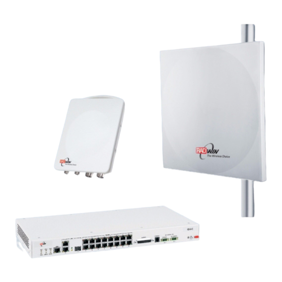
Figure 1-10: ODU with integrated Flat Panel antenna External antennas are available for the RADWIN 2000 radios, varying in operating frequencies, form factor, size and gain, dual or single polarization. -
Page 30: Radwin Network Management System (Rnms)
It offers users complete visibility and control over their RADWIN-based net- works. Accessories RADWIN provides a variety of accessories to support the RADWIN 2000 sys- tem: RADWIN 2000 User Manual Release 2.4 1-11... -
Page 31: Documentation Set Supplied With Radwin 2000
How to Use this Manual This User Manual is divided into three functionally distinct sections reflecting the activities required to set up a RADWIN 2000. The division is shown in the following table: Table 1-1: User Manual - General layout... -
Page 32: A Little Terminology
. Which is which, is always determined by the loca- tion of the managing computer. RADWIN 2000 supports three connection methods for the managing com- puter: Local • - a direct peer to peer connection between the Ethernet ports on the managing computer and the IDU or PoE device. -
Page 33: Conventions Used In This Manual
• Draw your attention to something that may not be obvious or coun- ter-intuitive • Emphasize a special feature or peculiarity of the RADWIN 2000 • Offer an external reference for additional information • Add a caveat that would not qualify as a full Caution or Warning (see... -
Page 34: Windows Terminology
Windows Terminology Chapter 1 Figure 1-13: Menu navigation in the RADWIN Manager Similarly, mouse click items will be referred to like this: “Click Next to continue.” (A mouse click always uses the left mouse button unless stated otherwise.) Windows Terminology... -
Page 35: Viewing And Printing
For good legibility, use a commercial grade laser printer. A color printer is of course best, however a monochrome printer set to use gray-scale gives acceptable results • Better quality inkjet printers also give good output RADWIN 2000 User Manual Release 2.4 1-16... -
Page 36: Chapter 2 Site Preparation
RADWIN 2000 offers a wide operating frequency range. A free frequency channel must be determined within the operating range, for optimum per- formance. -
Page 37: Stage 1: Preliminary Survey
5. Determine and record the compass bearings between both ODUs, rela- tive to north. 6. If there are obstructions between the two sites, calculate the Fresnel Zone (see Appendix B for details). 7. If the site chosen does not meet requirements, consider alternative sites. RADWIN 2000 User Manual Release 2.4... -
Page 38: Stage 2: Physical Survey
Chapter 2 8. Use the Link Budget Calculator (on the CD supplied with the equipment or using the RADWIN Manager) to determine the expected performance. Stage 2: Physical Survey The physical site survey reviews the environment of the proposed installa- tion location, to ensure that the link sites are suitable for the wireless net- work. -
Page 39: Additional Outdoor Site Requirements
Allow 2-4 hours duration for a good RF survey. It is possible to install the link and use the RADWIN Manager to find a clear channel. Each frequency channel can be evaluated in turn. Achievement of a... -
Page 40: Chapter 3 Hardware Installation
Chapter 3 Hardware Installation This chapter sets out the requirements and procedures for the hardware installation and alignment of a RADWIN 2000 link in accordance with the prior planning as set out in Chapter 2. It is intended to guide qualified field technicians. -
Page 41: Protection Against Lightning
It also lays down the size of grounding conductors and connection requirements for grounding electrodes. The RADWIN 2000 ODU must be grounded to a Protective Earth as described in Appendix C and in accordance with the Local Electrical Regulations. -
Page 42: Package Contents
Package Contents Chapter 3 Package Contents The RADWIN 2000 packages include the following items: ODU Package Contents The ODU package contains: • One ODU - see Figure 3-2 Figure 3-3 below for front and rear view • An ODU mounting kit - see... -
Page 43: Idu-C Package Contents
• Two DC power plugs for power cables - see Figure 3-6 below Figure 3-4: IDU-C Package contents - the IDU-C, Ethernet only Figure 3-5: IDU-C Package contents - the IDU-C, 16 E1/T1 ports RADWIN 2000 User Manual Release 2.4... -
Page 44: External Antenna Package Contents
ODU-IDU cable (outdoor class, CAT-5e, 4 twisted pairs, 24AWG) • For PoE based links: A crossed Ethernet LAN cable Hardware Installation Sequence The following steps are required to install the RADWIN 2000 system: 1. Mounting the ODUs, page page 3-7. -
Page 45: Outdoor Installation
7. Aligning the ODUs/antennas, page page 3-13. Figure 3-7 below, which illustrates a typical installation of RADWIN 2000 with an external antenna. Figure 3-7: Typical Installation Diagram (with external antenna) The installation steps are detailed in the following sections. Outdoor installation Preparing the ODU before Deployment Each ODU must be pre-loaded with an IP address. -
Page 46: Mounting The Odu
A mast-sited ODU typically uses a pole attached to the mast. Note A RADWIN 2000 link operates in pairs of two ODUs with the same configu- ration. Both ODUs must be installed, and the antennas aligned for maxi- mum throughput. -
Page 47: Mounting The Lightning Protection Devices
The use of lightning protection is dependent on regulatory and end user requirements. The RADWIN 2000 ODU is designed with surge limiting cir- cuits to minimize the risk of damage due to lightning strikes. RADWIN rec- ommends the use of additional surge arrestor devices to protect the equipment from nearby lightning strikes. - Page 48 ODU Port RJ-45 connector, see Table K-1. LAN RJ45Ports Ethernet, RJ-45 connector, see Table K-3. LAN SFP Port Appendix Alarm Ports Standard DB25 female connector, see Table K-7. Label indent Place for adhesive identification labels. RADWIN 2000 User Manual Release 2.4...
- Page 49 Alarm detected at the opposite site interface; Normal or LOSS Blinking Orange Local or remote loopback Alarm detected at this site interface Ethernet only IDU or E1/T1 not configured See supplementary Table 3-3 following. RADWIN 2000 User Manual Release 2.4 3-10...
-
Page 50: Connecting Power To The Idu
Note Connecting power to the IDU The IDU-C has redundant power connection circuits (items G and H in Figure 3-8 above). An enlarged schematic of the power connectors is shown in below: RADWIN 2000 User Manual Release 2.4 3-11... -
Page 51: Connecting The Odu To The Idu
PoE device, secure the cable along its path and connect the cable to the LAN-OUT RJ-45 connector on the PoE device. 2. Connect it to AC power. 3. Repeat steps 1 to 2 for the second link. RADWIN 2000 User Manual Release 2.4 3-12... -
Page 52: Connecting User Equipment
Connecting and Aligning ODUs / Antennas You perform antenna alignment using the ODU's audible tone. To speed up the installation time, alignment of a RADWIN 2000 system should be performed by two teams simultaneously, at site A and at site B. - Page 53 3. On both sides of the link, disconnect the antenna connected to the ODU connector ANT 1. Connect the other antenna to connector ANT 1 and fol- low the steps 3 to 7 above to align the second antenna. RADWIN 2000 User Manual Release 2.4 3-14...
- Page 54 Connecting and Aligning ODUs / Antennas Chapter 3 4. Secure the antennas to the pole/wall. 5. Restore one of the antennas to ANT 2 on both sides of the link. RADWIN 2000 User Manual Release 2.4 3-15...
-
Page 55: Installing The Radwin Manager Application
• Microsoft Explorer version 5.01 or later Installing the Software Any PC running the RADWIN Manager application can be used to configure a RADWIN 2000 link. To install the RADWIN Manager application: 1. Insert the CD into the CD/DVD drive of your computer. - Page 56 Getting Started with the RADWIN Manager Chapter 4 2. Choose Install RADWIN Manager and follow the on-screen instructions of the installation wizard to complete the setup of the RADWIN Manager application. If the installation program fails to start, browse to your CD/DVD drive, chose the setup.exe program and run it.
-
Page 57: The Radwin Manager Log-On Concept
The Log-on dialog box appears. Figure 4-3: First time log-on window The RADWIN Manager log-on Concept The RADWIN Manager provides three levels of access in one of two entry modes. To see them, click Options at any time in the Log on window extended (Figure 4-3 above). - Page 58 The RADWIN Manager log-on Concept Chapter 4 Figure 4-4: Extended log-on window If you do not have a direct connection to your target ODU (for example, you must go through a firewall), and if the RNMS Server is available, you may connect to it by checking the Connect through RNMS Server check-box and entering the RNMS IP Address.
- Page 59 The RADWIN Manager log-on Concept Chapter 4 Observer • has read-only access to the link. An Observer can monitor the link, generate reports, but may not change any link parameters. Operator • can install and configure the link. Installer •...
-
Page 60: Log-On Errors
If Community values were previously defined, enter them under Community in the Read-Only or Read-Write boxes. • If you are a user with read-only permission, then you may only log on as Observer. The RADWIN Manager main window is displayed (see Figure 4-8). Log-on Errors Unsupported Device... -
Page 61: Incorrect Password
Continuing without an IP Address The RADWIN Manager provides limited “offline” functionality when there is no accessible IDU/ODU. It is primarily for setting managing computer related parameters, running the Link Budget Calculator or viewing online Help. -
Page 62: Changing The Log-On Password
192.168.1.102. The Subnet Mask for both sites is 255.255.255.0 and the Default Gateway is left unset. We will maintain this arrangement throughout the remainder of this manual. At this point the main window of the RADWIN Manager should be displayed: RADWIN 2000 User Manual Release 2.4... - Page 63 First steps Chapter 4 Figure 4-8: Opening RADWIN Manager window prior to installation - IDU-C The Dynamic Tx Ratio bar only appears for model RADWIN 2000 C Note A detailed field by field description of the contents of the RADWIN Manager...
-
Page 64: Default Settings
• Configuration mode may vary the service throughput and quality, but without a service break Default Settings The default settings of the RADWIN 2000 configuration parameters are listed in the second column of Table 4-4 below. The third column shows the values we use in this manual for illustrative purposes. -
Page 65: Using Radwin Manager Spectrum View
5), you may use the RAD- WIN Manager Spectrum View utility. The RADWIN Manager Spectrum View utility is an RF survey tool designed to support the link installation prior to full link service activation. The tool provides comprehensive and clear information enabling easier, faster and better quality installations. - Page 66 Using RADWIN Manager Spectrum View Chapter 4 Appendix I for detailed information about operating Spectrum View and understanding the displayed statistics. RADWIN 2000 User Manual Release 2.4 4-12...
-
Page 67: Chapter 5 Installing The Link
Services: Ethernet + 7xE1 on ports 1, 2, 3, 8, 10, 11, 14. It is unlikely that you would use a non-contiguous set of ports - but this shows that if required, it can be done. The Installation wizard has seven steps as shown in Table 5-1 below. RADWIN 2000 User Manual Release 2.4... - Page 68 Channel settings - ACS Configuration Tx Power and antenna settings, MIMO or Diversity HSS Settings Services - Types • Ethernet • Adaptive or fixed, Jitter Buffer, MHS Set TDM Clock Parameters Wizard summary and completion RADWIN 2000 User Manual Release 2.4...
-
Page 69: Installation
Installation Step 1, Start the Wizard In the tool bar of the RADWIN Manager main window, click the Link Installation button. The Link Installation button is only accessible if the antennas are properly aligned. If this box is “grayed out”, you should align... - Page 70 If the Link Password is incorrect a link is established but configuration cannot be performed and no services are available. A new link password may be obtained from RADWIN Customer Support or use the alternative password supplied with the product.
-
Page 71: Changing The Link Password
2. Enter the current link password (The default link password for a new wireless-bridge ODU is If you have forgotten the Link Password, click the Forgotten Link Pass- word button. The following window is displayed: Figure 5-4: Lost or forgotten Link Password recovery RADWIN 2000 User Manual Release 2.4... -
Page 72: Step 3, Channel Settings
8-12. Step 3, Channel Settings RADWIN 2000 systems have a feature called Automatic Channel Selection (ACS). In the event of sync loss, ACS chooses the first available channel in a list of monitored channels nominated in the Channel settings window of Figure 5-5 below. -
Page 73: Step 4, Tx Power And Antenna Settings
No serv(ice) (red) to Ethernet + TDM (green) as shown in the bottom of Figure 5-6 above. 3. Click Next. Step 4, Tx Power and Antenna Settings The Tx Power and Antenna Parameters dialog appears. RADWIN 2000 User Manual Release 2.4... -
Page 74: About Single And Dual Antennas
About Single and Dual Antennas Each RADWIN 2000 ODU is made of two radio transceivers (radios). The radios make use of algorithms that utilize both MIMO and Diversity resulting in enhanced capacity, range and link availability. The number of antennas (i.e. -
Page 75: Single Antennas At Both Sites
(For example, by using dual polarization antennas a cross polarization separation is attained). Upon selecting Antenna Type as Dual, RADWIN 2000 automatically selects MIMO mode and doubles the air rates. RADWIN Manager indicates a case of unbalanced RSS between the two antennas. - Page 76 Site A Site B MIMO 50 Mbps Diversity 25 Mbps 25 Mbps 25 Mbps 25 Mbps The rates used by RADWIN 2000 are shown in Table 5-3 below: Table 5-3: RADWIN 2000 Air rates Air-Rate Antenna Modulation [Mbps] Single BPSK...
-
Page 77: Considerations For Changing Antenna Parameters
Installation Chapter 5 Table 5-3: RADWIN 2000 Air rates (Continued) Air-Rate Antenna Modulation [Mbps] Dual 64QAM Dual 64QAM Considerations for Changing Antenna Parameters Let: maxAvailableTx Power denote the maximum Tx Power practically avail- able from an ODU. It appears as Tx Power per Radio in Figure 5-8 below. - Page 78 Note × ≈ milliWatts (for two radios) then dBm will increase by If you choose to set the Antenna Gain and Cable Loss, you will receive the following warning message: RADWIN 2000 User Manual Release 2.4 5-12...
- Page 79 EIRP is maxAvailableTx Power + Antenna Gain - Cable Loss The table in Figure 5-11 only shows rates where the maximum Tx Power is the limitation, rather than regulations. When you close the win- RADWIN 2000 User Manual Release 2.4 5-13...
- Page 80 There are intermediate modes available for dual antennas opposite a sin- gle antenna as set out on page 5-8 above. If you make a change you will see a warning similar to this: RADWIN 2000 User Manual Release 2.4 5-14...
-
Page 81: Step 5, Hub Site Synchronization Settings
The Synchronization Status dialog box displays the current status of each side of the link. See Appendix G for instructions about installing and con- figuring collocated links. If you do not require HSS, click Next. Step 6, Services The Services dialog appears: RADWIN 2000 User Manual Release 2.4 5-15... - Page 82 Installation Chapter 5 Figure 5-14: Services and Rates dialog - RADWIN 2000 C only Figure 5-15: Services and Rates dialog for a collocated link or models RAD- WIN 2000 L and RADWIN 2000 PDH For - • a collocated link •...
-
Page 83: Restrictions On The Use Of Asymmetric Allocation
Table 5-4: Asymmetric Allocation with Collocated Links - Scenarios Scenario: If HSS Master HSS Client Result Remarks you try to... RADWIN 2000 Change master to asymmetric WinLink™ 1000 Link down Reversion to 50/50 restores link RADWIN 2000 User Manual Release 2.4 5-17... -
Page 84: Asymmetric Allocation And Tdm
Your Ethernet capacity allocation will be reflected in Figure 5-30 below. TDM Services selection To select services: 1. Click the Configure button. The TDM services dialog is displayed: RADWIN 2000 User Manual Release 2.4 5-18... - Page 85 Maximum button to choose all available ports or click on individual ports to choose them. • Ethernet is always selected. • The maximum available services will be reduced in accordance with actual air interface capacity. Note RADWIN 2000 User Manual Release 2.4 5-19...
- Page 86 The selected ports will be enabled for both sides of the link. You cannot for example, use ports 1, 3, 5, 7 on one side and 2, 4, 6, 8 Note on the other. RADWIN 2000 User Manual Release 2.4 5-20...
-
Page 87: Modulation Rate Selection
I. The following procedure can be used to switch links between primary and secondary or to disable the mode. To set the Hot Standby Mode: 1. Click the Hot Standby tab. The following dialog appears: RADWIN 2000 User Manual Release 2.4 5-21... -
Page 88: Setting The Tdm Jitter Buffer
2. Click the radio button to make this link primary or secondary. Setting the TDM Jitter Buffer To set the TDM Jitter Buffer size: 1. Click the TDM Jitter Buffer tab. The following dialog appears: RADWIN 2000 User Manual Release 2.4 5-22... - Page 89 During the evaluation the TBFR (TDM Block Failure Ratio)bar is displayed. You select either Next, which per- forms the change or Back to cancel the change. Notice that the Jitter Buffer is configured per site. RADWIN 2000 User Manual Release 2.4 5-23...
-
Page 90: Figure 5-24 Services And
2. After setting the jitter buffer size, if grayed out, the Evaluate button is enabled while both Back and Next are disabled as shown in the next figure: Figure 5-24: Services and TDM delay set - link ready for evaluation RADWIN 2000 User Manual Release 2.4 5-24... -
Page 91: Step 7, Tdm Clock Configuration
The optimum transmission rate for the selected services is evaluated. Following a short delay for processing, Back and Next are enabled. 4. Click Next to continue. The transmission rates used by RADWIN 2000 are shown in Table 5-3 above. Note... - Page 92 The Site A port receive-clock is used as the transmit-clock for that port on both sides of the link. Recover/Loop time The Site B port receive-clock is used as the transmit-clock for that port on both sides of the link. Internal/Recover RADWIN 2000 User Manual Release 2.4 5-26...
-
Page 93: Step 8, Installation Summary And Exit
4. Click Finish to complete the wizard. Step 8, Installation Summary and Exit Figure 5-28: Installation Wizard Exit Summary Click Done to return to the main window. The main window now reflects the installation: RADWIN 2000 User Manual Release 2.4 5-27... -
Page 94: Figure 5-29 M
Installation Chapter 5 Figure 5-29: Main window of the Manager after installation with loaded trunks RADWIN 2000 User Manual Release 2.4 5-28... -
Page 95: Figure 5-30 M
Figure 5-30: Main window of the Manager after installation with asymmetric capacity allocation - No HSS Figure 5-30 shows the results of a 70%/30% Transmission ratio on a lone link (no HSS). Observe that near 100Mbs is available in either direction RADWIN 2000 User Manual Release 2.4 5-29... -
Page 96: Figure 5-31 M
Site:B and Installation Mode in the Site Configuration dialog. Some Installation mode functionality may cause a break in, or degrade link service. Caution If you can accomplish link changes without affecting the service, always prefer to use Configuration mode, described in Chapter RADWIN 2000 User Manual Release 2.4 5-30... -
Page 97: One Manager For All Radwin Radio Products
Chapter 6 The RADWIN Manager: Main Window One Manager for all RADWIN Radio Products The RADWIN Manager application is largely generic to all RADWIN Radio Products. Functionality differences are minimal according to radio series (RADWIN 2000 and WinLink™ 1000) capabilities. -
Page 98: The Radwin Manager Toolbar
Chapter 6 Figure 6-1: Main window, Wireless Link is Active The main window of the RADWIN Manager contains a large amount of information about the link. Before proceeding to details of link configuration we set out the meaning of each item in the main window. -
Page 99: Main Menu Functionality
Get Diagnostics Obtain system information Clear Counters Clears TDM error blocks counters. Disabled for Ethernet-only link Log off Closes the current session and logs off RADWIN Manager Exit Exits RADWIN Manager Main Menu Functionality The main menu contains the following items:... -
Page 100: Elements Of The Radwin Manager Main Window
Elements of the RADWIN Manager Main Window Chapter 6 Table 6-2: RADWIN Manager main menu functionality (Continued) Menu level Function Reference Performance On screen and printable Monitoring Report Shows active alarms for <Site 1 1 <Site 1 name> name> Chapter 9 Active Alarms Shows active alarms for <Site 1... - Page 101 It includes the following panes (top to bot- tom): • Radio Interface, Received Signal Strength (RSS) in dBm and Trans- mission Ratio: The Dynamic Tx Ratio bar only appears for model RADWIN 2000 C Note • Ethernet Service: RADWIN 2000 User Manual...
-
Page 102: Figure 6-2 Ethernett
Elements of the RADWIN Manager Main Window Chapter 6 • Estimated Ethernet Throughput: The numbers are the current calculated throughputs at each site. The colored bars (with numbers) indicate the maximum possible throughput having regard for air conditions. • Rx and Tx Rates: Actual Ethernet traffic received and transmit- ted rates per site, in Mbps of Fps, selectable in the panel tile bar. - Page 103 The Status bar, displays the following icons: Table 6-3: Status bar indicators Icon or Label Purpose Connectivity Shows if RADWIN Manager is communicating with the ODU. Connection mode to the ODU • Over-the-Air connection - using the IP address of the remote unit. •...
- Page 104 Link Lock mismatch DFS in use Rescue Alarm In the event of an active alarm, opens alarms dialog RADWIN RNMS users will see an additional field showing the IP address of the RNMS server: RADWIN 2000 User Manual Release 2.4...
-
Page 105: Chapter 7 Configuring The Link
Configuring the Link Overview This chapter describes the link configuration procedure, which is performed after the installation of both sides of the RADWIN 2000 link, as set out in Chapter Link configuration uses a Link Configuration wizard to redefine the configu- ration parameters and fine-tune an operational link. - Page 106 Site details Channel settings - ACS Configuration HSS settings Tx Power and antenna settings, MIMO or Diversity Services - Types, Adaptive or fixed, Jitter Buffer, MHS Set TDM Clock Parameters Wizard summary and completion RADWIN 2000 User Manual Release 2.4...
-
Page 107: Configuration
Step 1, Start the Wizard In the tool bar of the RADWIN Manager main window, click the Link Con- figuration button. The Link Configuration button is only accessible on a fully installed link as set out in... -
Page 108: Step 3, Channel Settings
The System attributes may be edited and the Link Password may be changed exactly as in the corresponding Link Installation step on page 5- Click Next to continue. Step 3, Channel Settings Configuring the Channel Settings follows the same pattern as the Installa- tion procedure: RADWIN 2000 User Manual Release 2.4... -
Page 109: Figure 7-3 Channels
Notice that the operating channel is grayed out. If you use the Reselect Channel button, to change it, you will be asked for confirmation: If you accept, then the system will search for the best operating channel: RADWIN 2000 User Manual Release 2.4... -
Page 110: Figure 7-5 Channels
Figure 7-3 above with a possible change to the operating channel. If you work without automatic channel selection, the Channel Settings win- dow looks like this: Figure 7-5: Channel Settings without automatic channel selection RADWIN 2000 User Manual Release 2.4... -
Page 111: Figure 7-7 Choosing An Figure 7-8 Transmission
Selecting one of the frequencies presented returns you to the status of Figure 7-5 with the appropriate change. If you choose Other..., the fol- lowing window opens: Figure 7-7: Choosing an “Other” Operating Channel frequency RADWIN 2000 User Manual Release 2.4... -
Page 112: Step 4, Tx Power And Antenna Settings
±5MHz within a range of the operating band, which in this example is 5.740 - 5.835 GHz. For RADWIN 2000 radios, the Channel Bandwidth is fixed at 20 MHz. When you have completed making your choice, click Next to continue. -
Page 113: Switching Between Single And Dual Antennas
Switching Between Single and Dual Antennas Single/Dual Antenna mode selection works precisely the same way as shown on page 5-18. If you use this option you will receive a warning sim- ilar to this: RADWIN 2000 User Manual Release 2.4... -
Page 114: Switching Between Mimo And Diversity Modes
The Synchronization Status dialog box displays the current status of each side of the link. See Appendix G for instructions about installing and con- figuring collocated links. If you do not require HSS, click Next. Step 6, Services Here is the services dialog: RADWIN 2000 User Manual Release 2.4 7-10... -
Page 115: Step 7, Tdm Clock Configuration
• is Ethernet-only • uses model RADWIN 2000 C ODUs then you may use Asymmetric Allocation. You may change the capacity allo- cation here the same way as during installation. In place of the IDU box in Figure... -
Page 116: Step 8, Configuration Summary And Exit
Figure 7-12: TDM Parameters Configuration To configure the TDM Parameters, see the corresponding procedure in Chapter Step 8, Configuration Summary and Exit Figure 7-13: Configuration Wizard Exit Summary Click Done to return to the main window. RADWIN 2000 User Manual Release 2.4 7-12... -
Page 117: Figure 7-14 M
Configuration Chapter 7 The main window now reflects the configuration: Figure 7-14: Main window of the manager after configuration RADWIN 2000 User Manual Release 2.4 7-13... -
Page 118: Chapter 8 Site Configuration
Configuring the Site Editing the Configuration Parameters by Site You can edit the configuration parameters for each site individually. The fol- lowing functions are available from the left side of the dialog box. RADWIN 2000 User Manual Release 2.4... -
Page 119: Functions On The Left Of The Dialog Box
Return to Installation Mode for the entire link. Selecting the Mute check box before clicking the Install Mode button mutes the Beeper. Buzzer Mutes the alignment tone in installation mode. Reactivate the beeper during alignment. RADWIN 2000 User Manual Release 2.4... -
Page 120: Viewing System Details
Viewing System Details Chapter 8 To edit the Configuration Parameters: 1. Click the required site button on the main tool bar of the RADWIN Man- ager Click Configuration from the main menu and choose a site to config- ure. The Configuration dialog box opens (see Figure 8-1 above). -
Page 121: Hub Site Sync
Changing the Tx Power will affect service quality. The same considerations apply here as were noted in the Installation procedure on page 5-15. Caution Hub Site Sync Here you can view the HSS status: RADWIN 2000 User Manual Release 2.4... -
Page 122: Site Management: Ip Address And Vlan
To define the Management Addresses: 1. Choose a site to configure. The Configuration dialog box opens: Figure 8-5: Management Addresses - Site Configuration dialog box RADWIN 2000 User Manual Release 2.4... -
Page 123: Configuring Vlan Settings
Chapter 8 5. Choose Management. 6. Enter the IP address of the ODU in the IP Address field. If performing configuration from the RADWIN Manager, the IP address is that entered from the Login window. Note 7. Enter the Subnet Mask. -
Page 124: Lost Or Forgotten Vlan Id
VLAN. You may use this period to reconfigure the VLAN ID and priority. Displaying the Inventory To view the inventory data 1. Choose a site from the main menu. The Configuration dialog box opens. 2. Choose Inventory. RADWIN 2000 User Manual Release 2.4... -
Page 125: Security Features
Community strings and use the Link Lock feature: Figure 8-8: Available security features Changing the Link Password This item is only available when the link is down. Otherwise, it works the same way as the corresponding item on page 5-7. RADWIN 2000 User Manual Release 2.4... -
Page 126: Radwin Manager Community Strings
It is not possible to manage the ODU if the read-write or the read Commu- nity values are forgotten. A new Community value may be obtained from RADWIN Customer Support for the purpose of setting new Community. You must also have available the serial number or the MAC address of the ODU. -
Page 127: Forgotten Community String
Figure 8-10: Alternative Community Dialog box Link Lock Security Feature Link Lock is a part of RADWIN’s security concept intended to meet a form of abuse encountered in the field. It is designed to prevent the RADWIN 2000 User Manual Release 2.4... - Page 128 Link Lock can only be removed when the link is unsynchronized. In such a case, an alarm is raised by the RADWIN Manager. To enable Link Lock: 1. Click Site A on the main tool bar.
-
Page 129: Setting The Date And Time
Universal Coordinated Time (UTC). If there is no server available, you can either set the date and time, or you can set it to use the date and time from the managing computer. Note that manual setting is not RADWIN 2000 User Manual Release 2.4 8-12... -
Page 130: Figure 8-11 Date Andt
6. Set your site Offset value in minutes ahead or behind GMT 7. To manually set the date and time, click Change and edit the new values. 1. Greenwich Mean Time RADWIN 2000 User Manual Release 2.4 8-13... -
Page 131: Ethernet Properties
Bridge configuration is required in various network topologies, such as pro- tection (Ethernet 1+1) and ring applications. The bridge configuration parameters are located under the Advanced tab of the Site Configuration dialog box: RADWIN 2000 User Manual Release 2.4 8-14... -
Page 132: Odu Mode
MAC address learning table. The default value is 300 seconds. • Any change to these parameters is effective immediately. • Each side of the link can be configured separately, with different aging times. Note RADWIN 2000 User Manual Release 2.4 8-15... -
Page 133: Configuring Ethernet Ports Mode
Connect the system from the remote site • Connect via other Ethernet port (of the IDU) • Power down the equipment and connect immediately after power up (the fastest way is to enter install mode) RADWIN 2000 User Manual Release 2.4 8-16... -
Page 134: Setting The Maximum Information Rate (Mir)
The default value is "best effort" which will give Z above. The minimum value is 256 Mbps. The maximum value will be the minimum between Z above and - • 10 Mbps for RADWIN 2000 PDH • 50 Mbps for RADWIN 2000 L Note •... -
Page 135: Tdm Mhs Status
5. Choose Best Effort for the highest information rate possible for the link conditions and settings 6. Click Apply to save the changes. TDM MHS Status Here you can see the TDM MHS status. There is nothing to set. RADWIN 2000 User Manual Release 2.4 8-18... -
Page 136: Setting External Alarm Inputs
The ODU sends the alarm within less than a second from actual alarm trigger. To set the external alarm inputs: 1. Choose External Alarms from the Site Configuration window. Figure 8-18: External Alarms Configuration RADWIN 2000 User Manual Release 2.4 8-19... -
Page 137: Resetting
2. Choose Operations in the Configuration dialog box. Figure 8-19: Site Configuration - Reset to factory defaults 3. Click the Restore Defaults button. A message box asking if you want to restore factory default settings appears. RADWIN 2000 User Manual Release 2.4 8-20... -
Page 138: Idu Detection
Backup/Restore of ODU Software Files Backup ODU Software to a File RADWIN Manager allows you to backup the ODU software of both units of a link to the managing computer as binary files. Each site is backed up in a separate file. -
Page 139: Restoring Odu Software Or Configuration
It is possible to mute the tone during regular operation of the link. It must be enabled when performing the alignment procedure. To mute the alignment tone buzzer: 1. Choose a site. The Configuration dialog box opens. 2. In the Configuration dialog box, click the Buzzer button. RADWIN 2000 User Manual Release 2.4 8-22... -
Page 140: Configuration With Telnet
2. Click On to have the buzzer beep continuously or Auto to have the buzzer beep only in install mode. Configuration with Telnet A Telnet terminal can be used to configure and monitor the RADWIN 2000. To start a Telnet session, use telnet <ODU_IP>. For example, if you run Telnet as follows, telnet 192.168.1.101... - Page 141 <new location> Set the name of the location Set contact <new contact> Set the name of the site manager set Ethernet <>port:MNG,LAN1,LAN2> Set the mode and speed of each Ethernet port <mode:AUTO,10H,10F,100H,100F,DIS ABLE> RADWIN 2000 User Manual Release 2.4 8-24...
-
Page 142: Figure 8-22 Telnetm
<power:Value between minimal TX power, and maximal TX power> set bridge <mode:0=Bridging OFF,1=Bridging ON> set name <new name> set location <new location> set contact <new contact> set ethernet <port:MNG,LAN1,LAN2> <mode:AUTO,10H,10F,100H,100F,DISABLE> reboot help Command "help" finished OK. Figure 8-22: Telnet Management window RADWIN 2000 User Manual Release 2.4 8-25... -
Page 143: Chapter 9 Monitoring And Diagnostics
Chapter 9 Monitoring and Diagnostics The RADWIN Manager application enables you to monitor the link, as well as perform diagnostic operations such as loopback tests. This chapter covers: • Retrieving link information • Link compatibility issues • TDM port loopbacks •... -
Page 144: Link Compatibility
1. From the Help menu, choose Get Diagnostics Information. Figure 9-1: Get Diagnostics Dialog Box 2. Select or deselect the data options. If the file is to be sent to RADWIN Customer Support leave all options checked. 3. Click File Path to specify the folder in which you want to save the file and then click Start to save the information. -
Page 145: Tdm Loopbacks
Internal and external loopbacks on both sites of a link are used to test the TDM connections To activate a loopback: 1. From the Maintenance menu, choose Loopbacks... or right-click the TDM display in the main window. The Loopbacks dialog box appears: RADWIN 2000 User Manual Release 2.4... -
Page 146: Figure 9-4 Loopback Options
Figure 9-3: Loopback configuration box with one Site A port selected 3. Click configure to choose a loopback mode: Figure 9-4: Loopback options 4. Click the required loopback mode. RADWIN 2000 User Manual Release 2.4... -
Page 147: Figure 9-5 Loopback Defined
• Return to the situation of Figure 9-4 and click None. When a loopback is deactivated, the corresponding icon in Figure 9-6 reverts to its previous state (like the right side of the figure). RADWIN 2000 User Manual Release 2.4... -
Page 148: Local External Loopback
The remote unit can be set to an external loopback to test the remote E1/ T1 port and its connection to the remote side user equipment. In this mode, data coming from the remote user equipment is looped back to it locally. RADWIN 2000 User Manual Release 2.4... -
Page 149: Local Internal Loopback
It may be necessary to reinstall the link if the ODUs need to be realigned. Activating Install Mode causes both sites to go into install mode, causing disruption in service for approximately fifteen seconds. Note To reinstall the link: 1. Choose a site. The Configuration dialog box opens. RADWIN 2000 User Manual Release 2.4... -
Page 150: The Link Budget Calculator
Chapter The Link Budget Calculator The Link Budget Calculator is part of the RADWIN Manager software and is found in the Help menu. This useful utility enables you to calculate the expected performance of the wireless link and the possible configurations for a specific link range including antenna size, cable loss and climate condi- tions. -
Page 151: The Monitor Log
Select File dialog box indicate in which folder and under what name the monitor log file is to be saved. 6. Set the time interval for adding data to the file. 7. Click OK to save the file. RADWIN 2000 User Manual Release 2.4... -
Page 152: Viewing Performance Reports
2. Choose a report type from the left panel and click the Get Data toolbar button. For example, if you choose Site A, Air and Current, you will be offered a report looking like this: RADWIN 2000 User Manual Release 2.4 9-10... -
Page 153: Figure 9-13 Atypicalp
Refer to Table 9-3 Table 9-4 below. Data is collected and selectively displayed based on three time intervals as selected by the Interval radio buttons: • Current (t=0) • 15 minutes Intervals RADWIN 2000 User Manual Release 2.4 9-11... - Page 154 Seconds count when throughput fell below the threshold Traffic threshold Seconds count when actual traffic exceeded the threshold The number of seconds that the configured TDM services are TDM interface Active seconds active RADWIN 2000 User Manual Release 2.4 9-12...
-
Page 155: Performance Monitoring Report Toolbar
For links with Ethernet only service, 8% threshold is recommended. If there are no problems during the interval, then for that threshold, the recom- mended BBER value should be 0. Since the system provides a lossless RADWIN 2000 User Manual Release 2.4 9-13... -
Page 156: Events, Alarms And Traps
The foregoing event types include events from all links for which this managing computer has been defined as the traps address. Only events from RADWIN equipment will be shown. Note Alarms (traps) are displayed in the Events Log in the lower panel of the main window. -
Page 157: Figure 9-15 Events Log
Events Log file is to be saved, and click OK. To store the Events Log, first define the IP address, subnet mask, default gateway and trap destination address of the managing computer (see page 8-7 for details). Note RADWIN 2000 User Manual Release 2.4 9-15... -
Page 158: Radwin Manager Traps
RADWIN Manager Traps Chapter 9 RADWIN Manager Traps The RADWIN Manager application issues traps to indicate various events, displayed in the Events Log. Table 9-5: RADWIN Manager Trap Messages Trap Message Severity Remarks Cannot bind to trap service port. Port 162 already in use by... -
Page 159: Setting The Events Preferences
• Click Reset Settings to return to the default color settings. Saving the Events Log You can save recorded events in an Events Log text file. New alarms are automatically added to the text file, as they enter the Events Log. RADWIN 2000 User Manual Release 2.4 9-17... -
Page 160: Active Alarms
Refresh Shows the active alarms at the moment of refresh Site Selects site for the active alarms Close Closes the active alarm window Viewing Recent Events Each ODU stores the last 256 events: RADWIN 2000 User Manual Release 2.4 9-18... -
Page 161: Reverting Alert Messages
3. Use the Save button to store the events in a tab-delimited list. Reverting Alert Messages Many alert messages in the RADWIN Manager have an option of the form “Do not show this message again”. These alert messages can be reverted to... -
Page 162: Troubleshooting
Check that the IDU/ODU cable is properly wired and connected. Check that the IDU/ODU cable is properly wired and connected. Orange Complete the installation procedure from the RADWIN Manager AIR I/F Check the antenna alignment. Check that the radio configuration of both site A and site B units are the same (Channel and Link ID). -
Page 163: Replacing An Odu
Customer support for this product can be obtained from the local VAR, Inte- grator or distributor from whom it was purchased. For further information, please contact the RADWIN distributor nearest to you or one of RADWIN's offices worldwide (see RADWIN Worldwide Offices at the beginning of this manual). -
Page 164: Part 2: Advanced Installation
RADWIN 2000 Part 2: Advanced Installation Broadband Wireless Transmission User Manual Release 2.4 UM 2000-24/12.15... -
Page 165: Odu Mounting Kit Contents
Small Clamp (see Figure A-2) Arm (see Figure A-3) Screw hex head M8x40 Screw hex head M8x70 Washer flat M8 Washer spring M8 M8 Nuts Figure A-1: Large Clamp Figure A-2: Small Clamp Figure A-3: Arm RADWIN 2000 User Manual Release 2.4... -
Page 166: Mounting An Odu On A Pole
Mounting an ODU on a Pole Appendix A Mounting an ODU on a Pole Figure A-4: Mounting on a pole RADWIN 2000 User Manual Release 2.4... -
Page 167: Mounting An Odu On A Wall
Mounting an ODU on a Wall Figure A-5: Mounting on a Wall Mounting an External Antenna Optional external antennas can be mounted on a pole. The external mount- ing kit varies according to the specific antenna model. RADWIN 2000 User Manual Release 2.4... -
Page 168: Appendix B Link Budget Calculator
Overview The Link Budget Calculator is a utility for calculating the expected perfor- mance of the RADWIN 2000 wireless link and the possible configurations for a specific link range. The utility allows you to calculate the expected RSS of the link, and find the type of services and their effective throughput as a function of the link range and deployment conditions. -
Page 169: Calculations
The Ethernet and configured TDM trunks throughput is calculated according to internal product algorithms. Availability The Service Availability calculation is based on the Vigants Barnett method which predicts the downtime probability based on a climate factor (C fac- tor). RADWIN 2000 User Manual Release 2.4... -
Page 170: Antenna Height
The Fresnel zone (pronounced "frA-nel", with a silent “s”) is an elliptically shaped conical zone of electromagnetic energy that propagates from the transmitting antenna to the receiving antenna. It is always widest in the middle of the path between the two antennas. RADWIN 2000 User Manual Release 2.4... - Page 171 The concept of the Fresnel zone is shown in Figure B-1 above. The top of the obstruction does not extend far into the Fresnel zone, leaving 60% of the Fresnel zone clear; therefore, the signal is not significantly attenuated. RADWIN 2000 User Manual Release 2.4...
-
Page 172: Running The Link Budget Calculator
Fresnel_zone. Running the Link Budget Calculator The Link Budget Calculator is supplied on the RADWIN Manager CD. It may be run stand-alone from the CD or from the RADWIN Manager application. To run the Link Budget Calculator from the CD: 1. - Page 173 Mozilla FireFox and Google Chrome users may see a warning mes- sage like this: • You may ignore it and continue. To use the Link Budget Calculator for RADWIN 2000: 1. Choose a band from the drop-down list. RADWIN 2000 User Manual Release 2.4...
-
Page 174: Figure B-4 Band Selector
Running the Link Budget Calculator Appendix B Figure B-4: Band selector 2. Enter the radio details. Note that Rate is chosen from a drop-down list: RADWIN 2000 User Manual Release 2.4... -
Page 175: Figure B-5 Rate Selector
3. If the required range between the two link sites is known, you may enter it directly. Alternatively, you may enter the latitude and longitude of each site in the link, in which case the distance between them will be calcu- lated and displayed. RADWIN 2000 User Manual Release 2.4... - Page 176 4. Located to the right of the green Coordinates button is a drop-down list of Climactic C Factor values. It is only available if you choose a non-adap- tive rate. RADWIN 2000 User Manual Release 2.4...
-
Page 177: Figure B-7 Climacticc F
Running the Link Budget Calculator Appendix B Figure B-7: Climactic C Factors For help about what these mean, click the ? button to the right of the list Figure B-7. Figure B-8: Climactic C Factor description RADWIN 2000 User Manual Release 2.4 B-10... -
Page 178: Figure B-9 World Map Showing
Note The Expected Performance parameters are calculated and displayed: • Expected RSS - the expected RSS that the RADWIN Manager shows when the RADWIN 2000 ODUs are optimally aligned • Services Type - max number of T1 or E1 trunks if “Max Trunks” is selected •... -
Page 179: Appendix C Lightning Protection And Grounding Guidelines
Warning This appendix is at best a guide. The actual degree of lightning protection required depends on local conditions and regulations. Note The RADWIN Lightning Protection System consists of the following compo- nents: • Grounding for the antenna coax cable •... -
Page 180: Grounding For Indoor/Outdoor Units
Figure C-1: Grounding antenna cables Grounding for Indoor/Outdoor Units ODU Grounding RADWIN Lightning Protection System uses a Shielded CAT-5e cable to inter- connect the Outdoor (ODU) and Indoor (IDU) units. However, this shielding does not provide a good lightning discharge path, since it can not tolerate the high Lightning Current surges. -
Page 181: External Lightning Surge Suppressors And Grounding
External Lightning Surge Suppressors and Grounding A Grounding Kit and Surge Arrestor Unit must be located near the ODU and properly grounded as illustrated in Figures below: Figure C-2: Grounding a typical pole installation RADWIN 2000 User Manual Release 2.4... - Page 182 External Lightning Surge Suppressors and Grounding Appendix C Figure C-3: Grounding a typical wall installation The next figure shows a close-up of the rear of grounded ODU: Figure C-4: ODU Surge Suppressor and grounding RADWIN 2000 User Manual Release 2.4...
-
Page 183: Figure C-5 Transtector
6. Connect the suppressor’s ground stud to a grounding point. Use the appropriate wire gauge and type, keeping the wire as short as possible, less than 1m (3’), between the stud and the site grounding point. RADWIN 2000 User Manual Release 2.4... - Page 184 6. Connect the suppressor’s ground stud to a grounding point. Use the appropriate wire gauge and type, keeping the wire as short as possible, less than 1m (3’), between the stud and the site grounding point. 7. Replace the cover RADWIN 2000 User Manual Release 2.4...
-
Page 185: Internal Esd Protection Circuits
Figure C-6: Surge Suppressor and grounding at building entry point Internal ESD Protection circuits RADWIN equipment is designed to meet the ETSI/FCC/Aus/NZ/CSA EMC and Safety requirements. To fulfill these requirements, the system's Tele- com lines at the ODU/IDU are Transformer-isolated and include internal ESD (Electro-Static-Discharge) Protection circuits. -
Page 186: Why This Is Needed
If you have connectorized ODUs, two N-type RF terminators The procedure The following procedure is generic to all RADWIN radio products. What you see on your running RADWIN Manager may differ in some details from the screen captures used to illustrate this Appendix. Note To Preolad an ODU with an IP address: 1. -
Page 187: The Procedure
6. At the log on window, choose Local Connection. Figure D-1: Log on Window for Local Connection admin 7. Enter the default password, . After a few moments, the RADWIN Manager main window appears: RADWIN 2000 User Manual Release 2.4... -
Page 188: Figure D-2 Opening
The procedure Appendix D Figure D-2: Opening RADWIN Manager window prior to installation 8. Click the un-grayed Site:Location button. The following dialog window appears: Figure D-3: Configuration Dialog Box 9. Click the Management item in the left hand panel. The following win-... -
Page 189: Figure D-4 Management
For example, the ODU used here is to be configured as follows: Figure D-5: ODU with IP Addressing configured 11. Click OK. You are asked to confirm the change: Figure D-6: Confirmation of IP Address change RADWIN 2000 User Manual Release 2.4... -
Page 190: Figure D-7 Mainw
13. Click Cancel to leave the open Management dialog. You may now exit the RADWIN Manager, or connect to another ODU. If you choose to con- nect to another ODU, after about a minute, the main window of the RAD-... -
Page 191: Why This Is Needed
An IDU-ODU cable The procedure The following procedure is generic to all relevant RADWIN radio products. What you see on your running RADWIN Manager may differ in some details from the screen captures used to illustrate this Appendix. Note RADWIN 2000 User Manual... -
Page 192: Figure E-1 Becomingi
3. Using a crossed LAN cable, connect the LAN-IN port of the PoE device to the Ethernet port of the managing computer. The ODU will commence beeping at about once per second, indicating correct operation. 4. Launch the RADWIN Manager. 5. Log on as Installer. Figure E-1: Becoming Installer wireless 6. -
Page 193: Figure E-2 Opening
The procedure Appendix E Figure E-2: Opening RADWIN Manager window prior to band change (default circled) 7. Click Tools | Change Band. The following window appears: Figure E-3: Change Band dialog The bands appearing in Figure E-3 are product dependent. To see which... -
Page 194: Figure E-5 Changeb
9. The Change Band warning is displayed. Click Yes to continue. Figure E-5: Change Band confirmation The change, which may take some time, is carried out: The result is reflected in the RADWIN Manager main window: RADWIN 2000 User Manual Release 2.4... -
Page 195: Changing Band For Dfs
Should you ever require such a key, the procedure is as follows: To enter a License key: 1. Log on as Installer (as for the previous procedure). 2. Click the Site:Location tool bar button from the main tool bar. RADWIN 2000 User Manual Release 2.4... -
Page 196: Figure E-7 Using Theo
Appendix E Figure E-7: Using the Operations window to enter a license key 3. Enter your license key and click Activate. 4. When it is accepted, click Cancel. License keys, where appropriate, are obtainable from RADWIN Customer Support. Note iiiiiii RADWIN 2000 User Manual Release 2.4... -
Page 197: Appendix F Software Upgrade
The default location of the software files is in the installation area, and can be used to restore factory defaults. The following procedure is generic to all RADWIN radio products. What you see on your running RADWIN Manager may differ in some details from the screen captures used to illustrate this Appendix. Note... -
Page 198: Upgrading An Installed Link
Appendix F The default sites shown in the Software Upgrade list panel belong to the currently link. The list may be empty if you are running the RADWIN Manager “offline”. 2. Click Add Site to add additional sites for upgrade. - Page 199 3. Having created an update list, click Upgrade Package to chose the rel- evant files. The default files are located in the SWU subdirectory in the RADWIN Manager installation area. They are currently named SWU_1k.swu and SWU_2k.swu. You may have to find them else- where, depending on your system.
- Page 200 If you do not, Caution following the next reset of the updated site, you could experience a link software mismatch which may affect service. See page 9-3 for details. RADWIN 2000 User Manual Release 2.4...
-
Page 201: Appendix G Reserved
Appendix G Reserved RADWIN 2000 User Manual Release 2.4... -
Page 202: Appendix H Hub Site Synchronization
What is Hub Site Synchronization? When several units are collocated at a common hub site, interference may occur from one unit to another. RADWIN ODU units support the collocation of up to 16 units at a central site. The RADWIN Hub Site Synchronization (HSS) method uses a cable con- nected from the master ODU to all collocated ODUs;... - Page 203 HSS Master, the link is dropped until the synchronization pulses resume. This setting prevents the unit from causing interference. The remote ODUs that are not located at the hub site, are called Indepen- dent Units. RADWIN 2000 User Manual Release 2.4...
-
Page 204: Hardware Installation
SYNC 1. 3. Connect the other end of the CAT 5e cable to the ODU connector labeled SYNC. 4. Tighten the protective seal that is on the prepared cable over the RJ-45 connector. RADWIN 2000 User Manual Release 2.4... -
Page 205: Odu/Hss Unit Connection Pinout
Under HSS, the TDD mechanism of the collocated radios transmits at the same time and receives at the same time. The cycle duration of transmit Radio Frame Pattern and receive is called (RFP) and with RADWIN 2000 it is always 1250 milliseconds. RADWIN 2000 User Manual Release 2.4... -
Page 206: Radwin 2000 Considerations
• RFP type E should be used if and only if RADWIN 2000 links are part of the HSS installation. • The RFP must be the same for each link within the collocated system. -
Page 207: Winlink™ 1000 Considerations
There is no technical reason to prefer a WinLink™ 1000 over a RADWIN 2000 or vice versa. It is however, recommended that you use the RADWIN 2000 as master, since it will enforce the correct RFP on the other collocated units. - Page 208 1. Click the Enabled check box 2. Click the Configure button The Hub Site Configuration dialog box with the current status of the ODUs is displayed. 3. Select the type of unit configuration from the drop-down list. RADWIN 2000 User Manual Release 2.4...
-
Page 209: Site Configuration
Take care to avoid incorrect configuration of bandwidth, RFP or to set multiple Hub Sync Masters, as system interference can occur. RADWIN Manager gives error messages and tool tips if the system is configured with Note mismatches. - Page 210 Site Configuration Appendix H Figure H-8: Site Configuration - Hub Site Sync dialog box RADWIN 2000 User Manual Release 2.4...
-
Page 211: Appendix I Spectrum View
Appendix I Spectrum View What is Spectrum View? The RADWIN Manager Spectrum View utility is an RF survey tool designed to support the link installation prior to full link service activation. The tool provides comprehensive and clear spectral measurement information enabling easier, faster and better quality installations. -
Page 212: Running Spectrum View In Installation Mode
Figure I-1: Starting the analysis To obtain a spectrum analysis: 1. Click Start Analysis. You are asked for confirmation: 2. Click Yes. After a few moments, the first results for the managing site appear: RADWIN 2000 User Manual Release 2.4... - Page 213 Figure I-2: Site A (manageing site) done The over-the-air site takes a little longer: Current channel Figure I-3: Site B (over- the-air site) done, showing current channel The analysis complete when the Start Analysis button reverts to green. RADWIN 2000 User Manual Release 2.4...
-
Page 214: Understanding The Spectrum View Display
Understanding the Spectrum View display Appendix I Understanding the Spectrum View display Information Displayed Figure I-4 shows an annotated display taken from a live link. Figure I-4: RADWIN 2000 Spectrum View - annotated display RADWIN 2000 User Manual Release 2.4... -
Page 215: Changing The Display
Indication of scanned and un-scanned channels • Indication of channels selected for ACS • Notation of the current operational channel of the RADWIN 2000 link • Time stamp of the last spectrum scan • Further, it supports zoom capability, selective view of antennas and... - Page 216 The zoom can be reversed using the System menu obtained by right-click- ing any of the Spectrum View display panels. It also offers display variations such as maximum, average and current power per channel. RADWIN 2000 User Manual Release 2.4...
- Page 217 If you click Show Max, each panel will show the peak values recorded dur- ing the analysis: Figure I-9: Effect of setting Show Max If you click Show Average, each panel will show the average values recorded during the analysis: Figure I-10: Effect of setting Show Average RADWIN 2000 User Manual Release 2.4...
-
Page 218: Restricting The Panels To Be Displayed
Your analysis can be saved in a CSV (comma separated values) text file. Use the Files menu item in the usual way: The Spectrum View information is logged as part of the Diagnostics Infor- mation to improve link and system diagnostics and remote support. It can RADWIN 2000 User Manual Release 2.4... - Page 219 Saving a Spectrum Analysis Appendix I be retrieved from the RADWIN Manager menu using Help |Get Diagnostic Information. Here is extract of a saved Spectrum View: Spectrum View - Site: A Frequency,Is Scanned,Last Scan Timestamp,Last NF-AntennaA,Last NF-AntennaB,Average NF-AntennaA,Average NF-Anten- naB,Max NF-AntennaA,Max NF-AntennaB...
-
Page 220: Management Integration
Management Integration Appendix I Figure I-13: Spectrum View CSV file imported into MS Excel Management Integration Spectrum view information is supported in RADWIN’s MIB and can be used by external Network Management applications. RADWIN 2000 User Manual Release 2.4 I-10... -
Page 221: Appendix J Fcc/Ic Dfs Installation Procedure
5.3 GHz FCC/IC or alternatively, they can be set up for these bands using the RADWIN Manager. The following procedure is generic to all relevant RADWIN radio products. What you see on your running RADWIN Manager may differ in some details from the screen captures used to illustrate this Appendix. Note FCC/IC 5.4/5.3 GHz Link Activation... -
Page 222: Fcc/Ic 5.4/5.3 Ghz Link Activation
FCC/IC 5.4/5.3 GHz Link Activation Appendix J 3. Run the RADWIN Manager and log in as Installer. You will see the follow- ing window: Figure J-1: Activating an ODU - Inactive link When the Manager Main Screen is displayed it appears with the Link Sta- tus label red and showing Inactive. - Page 223 If both ODUs are powered up, after a minute or so a link will be estab- lished. If you are still connected to the remote site (from the previous steps), the window of Figure J-3 will look like this: RADWIN 2000 User Manual Release 2.4...
-
Page 224: Fcc/Ic 5.4/5.3 Ghz Link Configuration
The Configuration procedure may be carried out from either site using the Configuration wizard as shown in Chapter Both sites in a FCC/IC 5.4/5.3 GHz Link must be configured identically. Note The only difference is in the Channel Settings window: RADWIN 2000 User Manual Release 2.4... - Page 225 Note Upon completion of the wizard, the Site configuration dialogs can be used in the usual way. Once operational, the RADWIN Manager window is the same as for other radio equipment models. Here is the RADWIN Manager main window upon completion of the wizard: RADWIN 2000 User Manual Release 2.4...
- Page 226 FCC/IC 5.4/5.3 GHz Link Configuration Appendix J Figure J-6: FCC/IC 5.4/5.3 GHz operational RADWIN 2000 User Manual Release 2.4...
-
Page 227: Appendix K Monitored Hot Standby Installation Procedure
Monitored Hot Standby Installation Procedure What is a RADWIN Monitored Hot Standby The RADWIN Monitored Hot Standby (MHS a.k.a 1+1) is a duplicated link set up as a primary link and a secondary link in hot standby mode as shown Figure K-1 below. -
Page 228: What Radwin Mhs Provides
The main service redundancy features of the RADWIN MHS are – • TDM service cut-over from the primary to the secondary link is com- pletely automatic •... -
Page 229: Purpose Of This Appendix
Standby operational mode. Who Should Read this This appendix is intended for persons responsible for the installation and maintenance of RADWIN MHS. To use it you need to know how to - • Install a RADWIN 2000 radio link •... - Page 230 Figure K-3: How to connect the IDUs to the Patch Panel • With RADWIN 2000 links you can protect up to 16 TDM ports. To pro- tect more than eight TDM ports use two Patch Panels at each site. •...
- Page 231 Notice that there is a new tab, "Hot Standby", in the Ser- vices Configuration panel: Figure K-4: Services Configuration Panel showing Hot Standby tab After you have configured TDM services, click the new Hot Standby tab: RADWIN 2000 User Manual Release 2.4...
- Page 232 11. At Site 1.2, reconnect the Hot Standby Patch panel to the external equipment. From this point on, we will simply refer to primary and secondary link (no capitalized names). At the end of the process, the RADWIN Manager main windows should look like this: RADWIN 2000 User Manual Release 2.4...
- Page 233 Installing a RADWIN MHS Appendix K Figure K-6: The primary link under normal operation RADWIN 2000 User Manual Release 2.4...
- Page 234 To see what happens following a cut-over from the primary link to the sec- ondary link, you need to have running two copies of the RADWIN Manager – one logged into the primary link, and one logged into the secondary link.
- Page 235 Appendix K Figure K-8: Primary link a few seconds before regular No-Link display It will then revert to the standard No-Link-available window. On the secondary link Manager window, you will see a window like this: RADWIN 2000 User Manual Release 2.4...
-
Page 236: Maintaining A Radwin Mhs Link
Maintaining a RADWIN MHS Link Appendix K Figure K-9: Secondary Link operating as the Hot Standby link Notice that the active link notice is highlighted in red, so that there is no mistaking which link is operational. Maintaining a RADWIN MHS Link IDU Replacement There are two situations, which must be treated differently. -
Page 237: Odu Replacement
To pre-configure an ODU: 1. Attach the new ODU to an IDU or a PoE device. 2. Run the RADWIN Manager and use Hot Standby tab of Figure K-5 above to configure the new ODU to Primary or Secondary mode as required. -
Page 238: Switching Logic
Manager main windows should look like this: Figure K-10: Primary link after the switch over to secondary link (After a few seconds the display moves to No-Link display, with TDM ports grayed out.) RADWIN 2000 User Manual Release 2.4 K-12... -
Page 239: Switching Back From The Secondary To The Primary Link
Following reversion from the secondary link to the primary link, the Manager main windows should look like this: RADWIN 2000 User Manual Release 2.4 K-13... - Page 240 Switching back from the Secondary to the Primary Link Appendix K Figure K-12: Primary link operating after the switch back from secondary RADWIN 2000 User Manual Release 2.4 K-14...
-
Page 241: System Operation Description
Backup operation • TDM services are carried by the secondary link Switching back to • Switching back to primary will occur as soon as the Primary link is fully functional for 1 primary second RADWIN 2000 User Manual Release 2.4 K-15... -
Page 242: Appendix L Reserved
Appendix L Reserved RADWIN 2000 User Manual Release 2.4... - Page 243 Appendix M Reserved RADWIN 2000 User Manual Release 2.4...
-
Page 244: Part 3: Technical Information
RADWIN 2000 Part 3: Technical Information Broadband Wireless Transmission User Manual Release 2.4 UM 2000-24/12.15... -
Page 245: Radio
Capacity RADWIN 2000 L: Up to 50 Mbps capacity (net throughput, full duplex) RADWIN 2000 PDH: Up to 16 E1/T1 services and up to 10 Mbps capacity (net throughput, full duplex) Range Up to 120 km / 75 miles... -
Page 246: Configuration
ITU-T G.703, G.826 Line Code E1: HDB3 @ 2.048 Mbps, T1: B8ZS/AMI @ 1.544 Mbps Latency Configurable 5-20 ms Impedance E1: 120Ω, balanced, T1: 100Ω, balanced Jitter & Wander According to ITU-T G.823, G.824 RADWIN 2000 User Manual Release 2.4... -
Page 247: Ethernet Interface
Power Consumption < 35 W (IDU+ODU) Environmental ODU: -35°C to +60°C / -31°F to +140°F Operating Temperatures IDU: 0°C to +50°C / 32°F to +122°F ODU: Up to 100% non-condensing, IP67 Humidity IDU: 90% non-condensing RADWIN 2000 User Manual Release 2.4... -
Page 248: Safety
ETSI EN/IEC 60950-1, EN/IEC 60950-22 EN/IEC 60950-1 47 CFR Class B, Part15, Subpart B ETSI EN 300 386, EN 301 489-1, EN 301 489-4 CAN/CSA-CEI/IEC CISPR 22-04 Class B AS/NZS CISPR 22:2004 Class B RADWIN 2000 User Manual Release 2.4... -
Page 249: Antenna Characteristics
The transmission range is a function of the antenna gain and transmitting power. These factors are limited by country regulations. The RADWIN 2000 may be operated with an integrated antenna attached to the ODU unit, or with an external antenna wired to the ODU via an N-type connector. -
Page 250: Odu-Idu Cable
Orange Power (+) Blue Power (+) White/Blue Power (−) White/Brown Power (−) Brown ODU/HSS Unit Connection Pinout Table O-2: ODU/HSS Unit Connection Pinout HSS UNIT Color RJ-45 RJ-45 White/Green Green White/Orange Orange Blue White/Blue RADWIN 2000 User Manual Release 2.4... -
Page 251: User Port Connectors
Transmit Data Tip TxTip Transmit Data Ring TxRing Receive Data Tip RxTip Receive Data Ring RxRing Hot Standby Port RJ-11 Table O-5: Hot Standby RJ-11 Port Pinout Signal HSB out HSB in Ground Ground RADWIN 2000 User Manual Release 2.4... -
Page 252: Idu (All Models) Alarm Connector
1 Amp. Such resistor is not required if the equipment con- nected to the IDU supports current limiting to 1 Amp. • The voltage of the input alarm must be within the range of -10 to -50 Note VDC. RADWIN 2000 User Manual Release 2.4... -
Page 253: Dc Power Terminals - Idu-C
Figure O-1: Example for connecting the alarm connector DC Power Terminals - IDU-C Table O-7: Terminal Block 3-pin -48VDC Function Right Chassis Center – Left DC Power Terminals IDU-C Table O-8: Terminal Block 3-pin -48VDC Function Right Chassis Center – Left RADWIN 2000 User Manual Release 2.4... -
Page 254: Idu-C Sfp Support
100baseFX Multimode fiber-optic (MMF) link spans up to 2km long 100baseLX Single-mode fiber optic (SMF) links pans up to 10km 100baseBX SMF single-strand link spans up to 10 km or 40 km E3T3/FE E3/T3 RADWIN 2000 User Manual Release 2.4... -
Page 255: Appendix Q Mib Reference
Appendix Q MIB Reference Introduction About the MIB The RADWIN MIB is a set of APIs that enables external applications to con- trol RADWIN equipment. The MIB is divided into public and a private API groups: • Public: RFC-1213 (MIB II) variables, RFC-1214 (MIB II) System and Interfaces sections •... -
Page 256: Community String
To control a link, all SNMP requests should go to the local site IP address. Table 4-4 for default Community strings. Private MIB Structure The sections in the private RADWIN MIB and its location in the MIB tree are shown in Figure Q-1 below: RADWIN 2000 User Manual Release 2.4... -
Page 257: Mib Parameters
“Description” column describes when the new value is effective. It is recommended that you perform the appropriate action to make the values affective immediately after any change. Where a change is RADWIN 2000 User Manual Release 2.4... -
Page 258: Supported Variables From The Rfc 1213 Mib
The total number of packets that higher-level protocols requested be transmitted to a non- unicast (i.e., a subnetwork-broadcast or subnetwork-multicast) address, including those that were discarded or not sent. a. x is the interface ID RADWIN 2000 User Manual Release 2.4... - Page 259 Read/Write Community String. The SNMP agent accepts only encrypted values. winlink1000OduTrapCommunity 1.3.6.1.4.1.4458.1000.1.1.17 DisplayString RW Trap Community String. This parameter is used by the Manager application to change the Trap Community String. The SNMP agent accepts only encrypted values. RADWIN 2000 User Manual Release 2.4...
- Page 260 Number of ODU network interfaces. winlink1000OduBridgeBasePortTable N/A ODU Bridge Ports table. winlink1000OduBridgeBasePortEntry N/A ODU Bridge Ports table entry. INDEX { winlink1000OduBridgeBasePortIndex } winlink1000OduBridgeBasePortIndex ODU Bridge Port Number. winlink1000OduBridgeBaseIfIndex IfIndex corresponding to ODU Bridge port. RADWIN 2000 User Manual Release 2.4...
-
Page 261: Mib Parameters
1.3.6.1.4.1.4458.1000.1.5.13 Integer Minimum center frequency in MHz. winlink1000OduAirMaxFrequency 1.3.6.1.4.1.4458.1000.1.5.14 Integer Maximum center frequency in MHz. winlink1000OduAirFreqResolution 1.3.6.1.4.1.4458.1000.1.5.15 Integer Center Frequency resolution. Measured in MHz if value < 100 otherwise in KHz. RADWIN 2000 User Manual Release 2.4... - Page 262 Channels’ availability per CBW. winlink1000OduAirRFD 1.3.6.1.4.1.4458.1000.1.5.26 Integer Current radio frame duration in microseconds. winlink1000OduAirRatesTable N/A Air Rate indexes table for current channel bandwidth. winlink1000OduAirRatesEntry N/A Air Rate indexes table entry. INDEX { winlink1000OduAirRatesIndex } RADWIN 2000 User Manual Release 2.4...
- Page 263 Channel BW of 20MHz in the specific Radio Frame Pattern. winlink1000OduAirHssRfpStr 1.3.6.1.4.1.4458.1000.1.5.40.8 DisplayString Hub Site Synchronization supported patterns winlink1000OduAirHSSHsmID 1.3.6.1.4.1.4458.1000.1.5.40.9 Integer A unique ID which is common to the HSM and all its collocated ODUs RADWIN 2000 User Manual Release 2.4...
- Page 264 Start and Restart. Not Supported value indicates that the feature is not supported on the device. Not Supported is not a configurable state. winlink1000OduAirRxPowerAntennaA 1.3.6.1.4.1.4458.1000.1.5.56.2 Integer Received Signal Strength in dBm of Antenna A. RADWIN 2000 User Manual Release 2.4 Q-10...
- Page 265 The latter lasts no more than a predetermined interval (default 30 sec). winlink1000OduAirDesiredNetMasterTxRatio 1.3.6.1.4.1.4458.1000.1.5.60.1 Integer RW This parameter is reserved to the element manager provided with the product. RADWIN 2000 User Manual Release 2.4 Q-11...
- Page 266 Indicates the integrity of the entry per interval of 24 hours. winlink1000OduPerfMonAirCurrTable N/A This table defines/keeps the air counters of the current 15 min interval. winlink1000OduPerfMonAirCurrEntry N/A This is an entry in the Current Interval Table. INDEX {ifIndex } RADWIN 2000 User Manual Release 2.4 Q-12...
- Page 267 RSL1 threshold per Day. winlink1000OduPerfMonAirDayRSLThresh2Ex Number of seconds Receive Signal Level ceed exceeded the RSL2 threshold per Day. winlink1000OduPerfMonAirDayMinTSL Current Min Transmit Signal Level per Day. winlink1000OduPerfMonAirDayMaxTSL Current Max Transmit Signal Level per Day. RADWIN 2000 User Manual Release 2.4 Q-13...
- Page 268 N/A This is an entry in the Interval Table. INDEX {ifIndex winlink1000OduPerfMonTdmIntervalIdx } winlink1000OduPerfMonTdmIntervalIdx This table is indexed per interval number. Each interval is of 15 minutes and the oldest is 96. RADWIN 2000 User Manual Release 2.4 Q-14...
- Page 269 1.3.6.1.4.1.4458.1000.1.7.2.1 IpAddress RW IP address of the server from which the current time is loaded. winlink1000OduAgnNTPCfgTimeOffsetFromU 1.3.6.1.4.1.4458.1000.1.7.2.2 Integer RW Offset from Coordinated Universal Time (minutes). Possible values: -1440..1440. RADWIN 2000 User Manual Release 2.4 Q-15...
- Page 270 N/A Entry containing the details of last traps. INDEX { winlink1000OduAgnLastEventsIndex } winlink1000OduAgnLastEventsIndex 1.3.6.1.4.1.4458.1000.1.7.4.2.1.1 Integer The index of the table winlink1000OduAgnLastEventsSeverity 1.3.6.1.4.1.4458.1000.1.7.4.2.1.2 Integer Current Trap severity. RADWIN 2000 User Manual Release 2.4 Q-16...
-
Page 271: Figure 5-28 Installation
N/A IDU Possible Services table. winlink1000IduSrvPossibleServicesEntry N/A IDU Services table entry. INDEX { winlink1000IduSrvPossibleServicesIndex } winlink1000IduSrvPossibleServicesIndex 1.3.6.1.4.1.4458.1000.2.2.10.1.1 Integer Table index Rate index of the air interface. RADWIN 2000 User Manual Release 2.4 Q-17... - Page 272 SFP venfor properties : Vendor Name PN and Revision. winlink1000IduBridgeTpAging 1.3.6.1.4.1.4458.1000.2.4.4.2 Integer RW Timeout in seconds for aging. Note that for this parameter to be effective the ODU must be configured to HUB mode. A change is effective immediately. RADWIN 2000 User Manual Release 2.4 Q-18...
- Page 273 -1 is used to indicate an undefined state. winlink1000IduTdmRemoteQualEval 1.3.6.1.4.1.4458.1000.2.6.9 Integer Estimated average interval between error second events during evaluation process. The valid values are 1-2^31 where a value of -1 is used to indicate an undefined state. RADWIN 2000 User Manual Release 2.4 Q-19...
- Page 274 Using the alternative parameter: winlink1000OduAdmIpParamsCnfg is recommended. winlink1000OduAdmGateway 1.3.6.1.4.1.4458.1000.1.1.8 IpAddress RW ODU default gateway. A change is effective after reset. The parameter is kept for backward compatibility. Using the alternative parameter: winlink1000OduAdmIpParamsCnfg is recommended. RADWIN 2000 User Manual Release 2.4 Q-20...
-
Page 275: Mib Traps
Community string or by the trap description text. Each trap contains a trap description and additional relevant information such as alarm severity, interface index, time stamp and additional parame- ters. RADWIN 2000 User Manual Release 2.4 Q-21... -
Page 276: Trap Parameters
%p. %p Is the date and time. configurationChanged normal Indicates that the ODU recovered from an error but there are configuration changes. Contains two parameters: 1 - Description: Configuration changed. Error code is: %n. 2 - %n number. RADWIN 2000 User Manual Release 2.4 Q-22... - Page 277 The trap is sent every time an alarm occurs in the External Alarm Input of port #4. Contains a single parameter which is its description: 1 - Description: External Alarm 4 - <User Text> - Alarm. RADWIN 2000 User Manual Release 2.4 Q-23...
- Page 278 This Trap is sent every time an External Alarm Input fault of port # 2 is cleared. Contains a single parameter which is its description: 1 - Description: External Alarm 2 - <User Text> - Alarm Cleared. RADWIN 2000 User Manual Release 2.4 Q-24...
- Page 279 %s 2 - %s Is the Eth. mode (speed & duplex) compatibleIdus normal Indicates that the ODU has identified compatible Idus on both sides of the link. desiredRatioCanNotBeAppliedClear normal Indicates Current UL/DL Ratio Is Equal To Desired Ratio. RADWIN 2000 User Manual Release 2.4 Q-25...
-
Page 280: Radwin Manager Traps
RADWIN Manager Traps The RADWIN Manager application issues traps to indicate various events. These traps are shown in the RADWIN Managerr Events Log. A list of Trap Messages as displayed by the RADWIN Manager is shown in Table 9-5. RADWIN 2000 User Manual Release 2.4... -
Page 281: External Alarms Specification
Service Alarm at Site B Permanently off Link is up or down without power failure Output 4 Power Failure at Site B Link Loss due to Power Failure at Site B indication within the last two seconds RADWIN 2000 User Manual Release 2.4... -
Page 282: Idu-C Alarms
Table R-2: IDU-C - Input Alarms Description Alarm On Alarm Off Alarm Description Conditions Condition Input 1 Input 2 User Defined Voltage in range Voltage > 0VDC External Alarm -10 to -50VDC Input 3 Input 4 RADWIN 2000 User Manual Release 2.4... - Page 283 The antennas used for the following transmitters must be installed so as to provide a minimum separation distance from by-standers as specified in the following tables. Safety Distances RADWIN 2000 Table S-1: Safety Distances for RADWIN 2000 FCC and IC Products Frequency Antenna Min. Safety FCC ID...
-
Page 284: Appendix T Regional Notice: French Canadian
Mise à la terre Tous les produits RADWIN doivent être mis à la terre pendant l'usage cou- rant. La mise à la terre est assurée en reliant la fiche d'alimentation à une prise de courant avec une protection de terre. En outre: •... -
Page 285: Protection Contre La Foudre
L'utilisation de dispositifs de protection contre la foudre dépend des exi- gences réglementaires et de l'utilisateur final. Toutes les unités extérieures RADWIN sont conçues avec des circuits de limitation de surtension afin de minimiser les risques de dommages dus à la foudre. RADWIN conseille l'util- isation d'un dispositif de parafoudre supplémentaire afin de protéger le... -
Page 286: Connecter La Terre À Idu-C
M8x40 • deux visses hex tête M8x70 • quatre rondelles plates M8 • trois rondelles élastiques M8 • deux écrous M8. Figure T-1: Figure T-2: Figure T-3: grande clame petite clame bras RADWIN 2000 User Manual Release 2.4... -
Page 287: Montage Sur Un Pylône
Montage sur un pylône Appendix T Montage sur un pylône Figure T-4: Montage sur un pylône RADWIN 2000 User Manual Release 2.4... -
Page 288: Montage Sur Un Mur
Montage sur un mur Appendix T Montage sur un mur Figure T-5: Montage sur un mur RADWIN 2000 User Manual Release 2.4... -
Page 289: Montage D'une Antenne Externe
à pivotement. 4. Attacher l'antenne au pylône en utilisant les deux courroies de fixation . Ajuster l'inclinaison nécessaire en utilisant l'échelle angulaire et serrer tous les boulons et écrous à la position requise. RADWIN 2000 User Manual Release 2.4... -
Page 290: Index
5-17 Advanced 8-14 8-16 8-17 and TDM services 5-18 Air Interface Installation 5-17 Air interface Restrictions 5-17 contact person Transmission ratio 5-17 Date and Time Date and time Ethernet settings External alarms RADWIN 2000 User Manual Release 2.4 Index 1... - Page 291 Climactic C Factors B-10 described Fresnel Zone, described Aging time 8-15 Internal data aging time, ODU Bridge Mode 8-15 Running Connecting to ODU 3-12 User input described License key IDU-C band Alarm Connector RADWIN 2000 User Manual Release2.4 Index 2...
- Page 292 Step 1 - Start Wizard Screen, Telnet 8-25 Step 2 - System Parameters Manager Software Step 3 - Channel Settings Change log on password Step 4 - Tx Power and Antenna Settings Events Log RADWIN 2000 User Manual Release2.4 Index 3...
- Page 293 Replacing an ODU 9-21 Connectorized Antenna described form factors Safety Practices iii-iv Installation, Mast and Wall Grounding Integrated Antenna Preventing overexposure to RF energy Mounting Kit Security Package Contents Link Lock 8-10 Preloading IP address RADWIN 2000 User Manual Release2.4 Index 4...
- Page 294 Ports Trap Destination Software Upgarde User Port Connectors Multiple sites Single Site Software Upgrade Spectrum View described 4-11 using TDM Services Clock configuration 5-25 Evaluation 5-24 in Link Budget calculation Jitter Buffer 5-21 RADWIN 2000 User Manual Release2.4 Index 5...
Need help?
Do you have a question about the 2000 and is the answer not in the manual?
Questions and answers