Radwin WinLink 1000 User Manual And Installation Manual
Radwin broadband wireless transmission system
Hide thumbs
Also See for WinLink 1000:
- User manual (348 pages) ,
- Installation and operation manual (97 pages) ,
- Installation and operation manual (71 pages)

Subscribe to Our Youtube Channel
Related Manuals for Radwin WinLink 1000


Summary of Contents for Radwin WinLink 1000
- Page 1 WinLink™ 1000 Broadband Wireless Transmission System User Manual and Installation Guide Version 1.750...
- Page 2 This Agreement is effective upon your opening of the WinLink™ 1000 package and shall continue until terminated. RADWIN may terminate this Agreement upon the breach by you of any term hereof. Upon such termination by RADWIN, you agree to return to RADWIN the WinLink™ 1000 and all copies and portions thereof.
- Page 3 RADWIN Worldwide Offices Corporate Headquarters India Headquarters 27 Habarzel Street Mohan Co-operative Industrial Estate Tel Aviv, 69710 E-13, B-1 Extn Israel New Delhi, 110044 Tel: +972.3.766.2917 India Tel: +91.11.40539180 Support Headquarters 27 Habarzel Street APAC Headquarters Tel Aviv, 69710 1 Jalan Kuala #13-01...
-
Page 4: Fcc – User Information
1000 warranty and may expose the end user or the service provider to legal and financial liabilities. Radwin and its resellers or distributors are not liable for injury, damage or violation of regulations associated with the installation of outdoor units or antennas. -
Page 5: Table Of Contents
Table of Contents FCC – USER INFORMATION........................ 1-4 CHAPTER 1 INTRODUCTION......................1-12 ..........................1-12 PPLICATIONS Cellular Backhaul ..........................1-12 Broadband Access..........................1-13 Private Networks..........................1-14 Video Surveillance ........................... 1-15 ™ 1000 K ......................1-15 EATURES TDM + Ethernet in one Solution...................... 1-15 Simple Installation ........................... - Page 6 WinLink™ 1000 with Automatic Channel Select ................3-47 WinLink 5.4 GHz ETSI Version ....................... 3-48 WinLink™ BRS Version........................3-49 ....................3-51 ELECTING THE ERVICE ARAMETERS ....................3-52 ETTING THE LOCK ONFIGURATION T1 L ........................3-54 ETTING THE TDM B IDU-R )..................
- Page 7 CHAPTER 6 MONITORING AND TESTING THE LINK ............. 6-103 ) .............. 6-103 ETRIEVING NFORMATION NFORMATION .......................... 6-104 OMPATIBILITY ......................... 6-105 ESTING THE ONNECTION Local External Loopback ....................... 6-106 Remote Internal Loopback ......................6-107 Remote External Loopback ......................6-108 Local Internal Loopback........................ 6-108 ....................
- Page 8 AIND A ..................11-143 ERFORMING LIGNMENT Equipment Setup .......................... 11-143 Aligning the antennas........................11-143 Configuring the Link..........................11-144 Evaluating the Link ..........................11-144 Troubleshooting ............................11-144 CHAPTER 12 APPENDIX D: ANTENNA ..................12-146 CHAPTER 13 APPENDIX E: HUB SITE SYNCHRONIZATION..........13-148 ........................
-
Page 9: List Of Figures
List of Figures 1-1: T ..............1-13 IGURE YPICAL ELLULAR ACKHAUL PPLICATION 1-2: T ................ 1-13 IGURE YPICAL ROADBAND CCESS PPLICATION 1-3: T ................1-14 IGURE YPICAL ACKHAUL PPLICATION 1-4: M ............1-14 IGURE ULTI OINT OINT NTERPRISE ONNECTIVITY 1-5: M .......... - Page 10 5-10: C ................5-82 IGURE ONFIGURATION INISH SCREEN 5-11: C .................... 5-84 IGURE ONFIGURATION IALOG 5-12: C ..................5-85 IGURE HANGING THE RANSMIT OWER 5-13: M ........5-86 IGURE ANAGEMENT DDRESSES ONFIGURATION DIALOG BOX 5-14: C VLAN S ................... 5-87 IGURE ONFIGURING ETTINGS...
-
Page 11: List Of Tables
List of Tables 2-1: ODU S ................2-22 ABLE ERIES YPICAL HARACTERISTICS 2-2: C ................2-25 ABLE ONFIGURABLE RANSMISSION PTIONS 2-3: R ..................2-25 ABLE ATES AND ERVICES UPPORTED 2-4: R ......................2-26 ABLE ADIO EGULATIONS 2-5: E ..................... 2-26 ABLE NVIRONMENTAL EGULATIONS... -
Page 12: Chapter 1 Introduction
Delivering high capacity connectivity of up to 48 Mbps at distances of up to 80 Km/50 miles, the WinLink 1000 products offer an unmatched combination of robustness and reliability at an affordable price. -
Page 13: Broadband Access
Key Applications Figure 1-1: Typical Cellular Backhaul Application Broadband Access With WinLink™ 1000, service providers can expand their service footprint rapidly and affordably, and provide high-capacity services that match the ever-growing demand for high-quality, high-speed broadband. WinLink™ 1000 is the ideal solution for last mile access, and also powers WiFi backhaul and WMAX backhaul applications. -
Page 14: Private Networks
RADWIN’s cost-effective solution enables organizations of all types to connect geographically dispersed buildings at ranges of up to 80 Km/50 miles. -
Page 15: Video Surveillance
WinLink™ 1000 Key Features Video Surveillance RADWIN's WinLink™ 1000 wireless broadband systems allow organizations and system integrators to deploy video cameras virtually anywhere while eliminating the costs and installation hassles of wire- based systems. Reliable, robust and affordable, the WinLink™ 1000... -
Page 16: Automatic Adaptive Rate
Unique Multi Point-to-Point Deployment RADWIN's WinLink™ 1000 products can be installed in a unique multi point-to-point architecture. Multiple units are deployed in one hub site location, from where they provide a dedicated, high-capacity connection to each remote site. - Page 17 How to Use this Manual It is recommended that you first read the Overview in the next chapter as this provides an understanding of the various parts of the system and how the system works. WinLink User and Installation Guide Version 1.750 1-17...
-
Page 18: Chapter 2 Overview
Chapter 2 Overview WinLink™ 1000 System Components WinLink™ 1000 point-to-point solution is made up of a number of key components. Typically, each side of the link comprises an Indoor Unit (IDU), an Outdoor Unit (ODU) and an antenna. A CAT5e cable from the IDU to the ODU provides both Ethernet and Power. -
Page 19: The Indoor Unit (Idu)
WinLink™ 1000 System Components The Indoor Unit (IDU) The IDU provides TDM and Ethernet ports to connect to the link. It also provides power to the ODU. The IDU is available in four configurations: IDU-E A compact, half 19 inch wide, 1U plastic unit, providing up to two Ethernet ports and up to two E1/T1 interfaces. -
Page 20: Power Over Ethernet Units
WinLink™ 1000 System Components Figure 2-7: Backup link for E1/T1 connections Power Over Ethernet Units Power over Ethernet units provide Ethernet services only. Power over Ethernet (PoE) An extremely compact device, the Power Over Ethernet (PoE) provides Ethernet only services through one Ethernet port. Figure 2-8: PoE Note: The PoE can only be connected to ODU’s that are PoE enabled, or that... -
Page 21: The Outdoor Unit (Odu)
WinLink™ 1000 System Components O-PoE Similar to the PoE, with weatherproof casing and sealed connectors that enables outdoor connectivity (a special mounting kit is supplied for attachment to a mast). Figure 2-9: O-PoE Unit The Outdoor Unit (ODU) The ODU is the radio transceiver of the WinLink system and is the main component of the system. -
Page 22: Figure 2-11: Typically Used
WinLink™ 1000 System Components Figure 2-11: Typically used External Antennas There are three series of ODU: • WinLink™ 1000 Access • WinLink™ 1000 • WinLink™ 1000 High End The following table shows the differences between the systems: Table 2-1: ODU Series Typical Characteristics WinLink™... -
Page 23: Winlink™ 1000 Manager
Link installation and Link configuration between the ODU units. The intuitive, easy-to-use Manager has a graphical MS- Windows interface, and can be utilized locally and remotely. WinLink 1000 Manager provides: Link Budget calculator • Planning tools such as a... -
Page 24: (All Indoor Unit) Aind
WinLink™ 1000 System Components (All Indoor Unit) AIND The AIND - All Indoor unit offers a single enclosure for Radio and Multiplexer modules. It enables outdoor placement of only a passive element. Figure 2-13: AIND - "All Indoor" unit connected to antenna WinLink User and Installation Guide Version 1.750 2-24... -
Page 25: Technical Specifications
Technical Specifications Technical Specifications Air Interface WinLink is available in several different frequency band ranges that comply with ETSI, FCC and IC regulations. Frequency Bands and Channel Bandwidth Table 2-2: Configurable Transmission Options 5.850-5.950 GHz 5.725-5.850 GHz 5.470-5.725 GHz Frequency Bands 5.150-5.350 GHz 4.940-4.990 GHz 2.500-2.700 GHz... -
Page 26: Regulations
Technical Specifications NOTE Before each installation you must use the Link Budget Calculator (Appendix H: Link Budget Calculator) to locate the supported rates and services for your particular product. Regulations WinLink operation complies with the radio and environmental regulations listed in the following tables: Table 2-4: Radio Regulations FCC 47CFR part 15 subparts B&C and E, part 27 and part 90... -
Page 27: Tdm (E1/T1) Services
Technical Specifications • Retry mechanism for loss-less connection (Fast ARQ) TDM (E1/T1) Services The WinLink TDM interface accepts E1 or T1 traffic, supporting unframed operation (E1 and T1) and AMI and B8ZS zero suppression (T1). TDM services include: • 1 to 4 E1/T1 interfaces in the indoor units •... -
Page 28: Technical Specification Summary
Technical Specifications Technical Specification Summary Table 2-6: Technical Specification Summary Technology Air Interface OFDM Duplexing Method Time Division Duplex (TDD) Capacity Configurable up to 48 Mbps Modulation OFDM - BPSK, QPSK, 16QAM, 64QAM Channel Resolution 5/10/20 MHz (ETSI systems do not support 5/10) (BRS systems Single and Double only) Transmitter Power Specification is different per product, for further... - Page 29 Technical Specifications Technology Air Interface OFDM IDU (green) IDU-C status ODU (green/red) ODU-to-IDU link status LINK (green/red) Link status SERVICE (green/red) E1/T1 signal status Source Power IDU-E: 100–240 VAC via external AC/DC converter IDU-C: 100–240 VAC via AC cable -20 to –60 VDC O-PoE: 100–240 VAC via attached (pigtail) AC cable PoE-8: 100–240 VAC via AC cable -20 to –60 VDC Max...
- Page 30 Technical Specifications Technology Air Interface OFDM Width 23.5 cm (9.3 in) 29 cm (11.5 in) Depth 16.5 cm (6.7 in) 43 cm (17.7 in) Weight 0.5 kg (1.1 lb) 1.5 kg (3.3 lb) Environment Outdoor Unit Enclosure All-weather case Temperature -35 to 60°C/-31 to 140°F Indoor Unit (IDU-E, IDU-E-AL, IDU-R, and IDU-C) Temperature...
-
Page 31: Chapter 3 Installation And Setup
Chapter 3 Installation and Setup This section describes the installation, alignment, and setup procedures for a WinLink system. Site Requirements and Prerequisites For the IDU units, allow at least 90 cm (36 in) of frontal clearance for operating and maintenance accessibility. Allow at least 10 cm (4 in) clearance at the rear of the unit for signal lines and interface cables. - Page 32 Package Contents • For AC model, 110/240 VAC with IEC 60320 socket cable • For DC model, 3-prong terminal block connector (green) • 19” mounting kit • Spare RJ-45 connector PoE-8 Package Containing: • PoE-8 • 110/240 VAC with IEC 60320 socket cable •...
-
Page 33: Installation Sequence
Installation Sequence Installation Sequence The following steps are required to install the WinLink system: 1. Install the management program on the network management station/laptop. See Installing the WinLink Management Software, page 3-35. 2. Mount the ODU at each site (and antenna if external antenna is used). - Page 34 Installation Sequence The following diagram illustrates a typical installation of WinLink™ 1000 with an external antenna. Figure 3-1: Typical Installation Diagram (with external antenna) The installation steps are detailed in the following sections. WinLink User and Installation Guide Version 1.750 3-34...
-
Page 35: Installing The Winlink Management Software
Installing the WinLink Management Software Installing the WinLink Management Software Minimum Requirements The WinLink management application is distributed on CD-ROM as an executable file. The application has the following PC requirements: • Memory: 128 MB RAM • Disk: 1 GB free hard disk space •... -
Page 36: Installing The Software
Mounting the ODU Installing the Software To install the WinLink management program: 1. Insert the CD-ROM into your CD-ROM drive. The WinLink™ 1000 Installation screen appears: 2. Choose Install WinLink™ 1000 Manager and follow the on-screen instructions of the installation wizard to complete setup of the WinLink™... -
Page 37: Connecting The Odu To The Idu
Connecting the ODU to the IDU Prior to connecting cables to the ODU, the protective earth terminal (screw) of the ODU must be connected to an external protective ground conductor or to a grounded mast. For grounding the O-PoE, connect the grounding cable from the dedicated earth terminal (screw at the side of the enclosure) to an external protective ground Warning conductor or to a grounded mast. -
Page 38: Figure 3-3: Idu-R Rear Panel
Connecting the ODU to the IDU the O-PoE or PoE-8 cable is 100m (328 ft) in accordance with 10/100BaseT standards. The ODU-IDU cable is supplied pre-assembled with RJ-45 connectors, at the length specified when ordering. If the ODU-IDU cable was not ordered, use Cat. -
Page 39: Connecting The Ground To The Idu
Connecting the Ground to the IDU Figure 3-6: PoE-8 Unit Figure 3-7: O-PoE Unit Note: Panels may be fitted with different connector combinations than shown, depending on the model ordered. Connecting the Ground to the IDU Connect an 18AWG grounding cable to the grounding terminal of the device. -
Page 40: Connecting Power To An O-Poe
Connecting Power to an O-PoE • Connect the power cable plug to the mains outlet. The unit turns on automatically upon connection to the mains. To connect DC power to an IDU A special 3-prong socket for DC power connection is supplied with the unit. -
Page 41: Figure 3-8: Beeper Sequence For
Aligning Antennas with the Beeper Provided that Site A detects the signal from Site B, the ODU starts beeping 20 seconds after power up, and continues beeping until the ODUs are aligned, and the installation is complete. 2. Verify normal operation of the IDU by the LED indications on the front panel. -
Page 42: Installing The Link
Installing the Link Installing the Link During the installation procedure, the definition of all parameters is automatically applied to both sides of the link. Note: For HSS screens see Appendix E: Hub Site Synchronization.. To install the link: 1. Verify that there is IP connectivity between the management station/laptop and the IDU, and that the WinLink™... - Page 43 Installing the Link 4. Click Next to proceed with the installation procedure. The system dialog box opens: Figure 3-10: Installation Wizard, System dialog box 5. Enter a SSID (System ID – must unique for each link in the area). The SSID must include at least eight alphanumeric characters. Up to 24 characters are allowed.
-
Page 44: Changing The Link Password
Installing the Link 9. Optionally enter a new Link Password (version 1.400 and after). See Changing the Link Password, page 123 for details on the Link Password. Note: If the Link Password is incorrect a link is established but configuration cannot be performed and no services are available. -
Page 45: Connecting The User Equipment
Connecting the User Equipment Figure 3-11: Change Link Password dialog box 2. Enter the default link password wireless-bridge. 3. Enter a new password. 4. Retype the new password in the confirm field. 5. Click OK. 6. Click Yes when asked if you want to change the link password. 7. - Page 46 Connecting the User Equipment Refer to Appendix A: Wiring Specifications, for the connector pinout. 2. Connect user hub/router or any other compatible device to the IDU panel RJ-45 port designated LAN. There may be multiple LAN ports available for connecting to different LANs depending on the IDU unit ordered.
-
Page 47: Selecting Channels
Selecting Channels WinLink systems later than version 1.300 have a feature called Automatic Channel Select, which allows you to define several alternative frequency channels if interference is detected on the channel in use. Note: For the ETSI version, skip to page 3-48; for the BRS version, skip to page 3-49. -
Page 48: Winlink 5.4 Ghz Etsi Version
Selecting Channels When changing the channel bandwidth, the WinLink Manager repeats evaluation of the link. 3. Click the check box if Automatic Channel Selection is required. 4. Click the check boxes in the Available Channels List of all the allowable channels that can be automatically selected. Selecting a new channel causes the system quality to change. -
Page 49: Winlink™ Brs Version
Selecting Channels 3. Click at least two check boxes in the Available Channels List of all the allowable channels that can be automatically selected. Note: Installation will not continue until at least two channels are defined. Selecting a new channel causes the system quality to change. The quality bar shows the adjustment until the system finds the best quality link. -
Page 50: Figure 3-14: Brs Channels
Selecting Channels Figure 3-14: BRS Channel Settings Post-Transition WinLink User and Installation Guide Version 1.750 3-50... -
Page 51: Selecting The Service Parameters
Selecting the Service Parameters Selecting the Service Parameters You define the type of service required, Ethernet Only or Ethernet with TDM in the Services screen as shown below. Notice that the Distance between the sites automatically appears in the Distance box (from Version 1.600). -
Page 52: Setting The Clock Configuration
Setting the Clock Configuration 2. In the Rate box, select the required transmission rate. If Adaptive is selected (refer to page 1-16 for information about Automatic Adaptive Rate), WinLink constantly monitors and adjusts the transmission rate to ensure maximum throughput for the link at the highest quality. - Page 53 Setting the Clock Configuration link. The user equipment must be configured as described in the following table. Table 3-2: TDM Clock Modes Unit Clock Mode User Equipment Side Local Unit Remote Unit HQ side Branch side Transparent Transparent Internal/Recover Internal/Recover Loop Time Recover Internal...
-
Page 54: Setting The T1 Line Code
Setting the T1 Line Code Figure 3-16: TDM Parameters dialog box Note: This dialog box is available with IDU-E and IDU-C units; it is activated after TDM service is chosen in the previous Service dialog box. In Ethernet only services, the TDM dialog box does not appear. Setting the T1 Line Code The T1 line code can be set as B8Zs or AMI in the TDM Parameters dialog box. -
Page 55: Setting The Tdm Backup (For Idu-R Only)
Setting the TDM Backup (for IDU-R only) Setting the TDM Backup (for IDU-R only) IDU-R units have two E1 trunk lines, one for WinLink air interface via the ODU, and the second external equipment such as a PBX. The TDM backup screen is displayed in IDU-R systems only. -
Page 56: Figure 3-18: Tdm Backups
Setting the TDM Backup (for IDU-R only) Figure 3-18: TDM Backup Service, IDU-R units only WinLink User and Installation Guide Version 1.750 3-56... -
Page 57: Figure 3-19: Installationw
Setting the TDM Backup (for IDU-R only) Figure 3-19: Installation Wizard, Finish Screen 3. Click Finish to complete the installation wizard. Verify that the Radio Signal Strength (RSS) is according to expected results as determined by the Link Budget Calculator. Verify that the Radio Signal Strength (RSS) numerical value is relative to the expected results that were determined by the Link Budget Calculator. -
Page 58: Chapter 4 Getting Started
Chapter 4 Getting Started This section provides the following information for WinLink: • Turning the system on and off • Starting the WinLink™ Manager software • Controls and indicators • Normal Indications • Default settings • Technical Specifications Turning On WinLink To turn on WinLink: •... -
Page 59: Odu/Lan Indicators
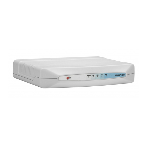
Controls and Indicators Figure 4-1: IDU-E Front Panel The following table describes the indicators: Table 4-1: Front Panel LEDs Name Color Function Green ON –Power supply is ON (IDU-E only) Green ON – IDU operational With Ethernet only Green ON – During power-up only With TDM Orange ON - During power-up only... -
Page 60: Idu Back Panel Indicators
Controls and Indicators IDU Back Panel Indicators Table 4-3: TDM Traffic Indicators Function Green LED Red LED Loopback Blinking Upon turning on WinLink, the PWR LED in the IDU-E front panel lights Table 4-4 to indicate that WinLink is on. shows the correct status of the indicators at power-up. -
Page 61: Starting The Winlink Manager Software
Starting the WinLink Manager Software Table 4-5: Default Settings Parameter Default Value ODU IP Address 10.0.0.120 Subnet Mask 255.0.0.0 Manager Login password Admin SSID – Link Password Wireless-bridge Rate Adaptive Services Ethernet Ethernet Configuration Auto Detect Radio Link Failure Actions No action Bridge Non PoE systems: Hub Mode, Aging time = 300 sec... -
Page 62: Figure 4-2: Login Screen
Starting the WinLink Manager Software Figure 4-2: Login Screen 3. For IP Address do one of the following: • Type an IP address for the ODU (for Network mode), OR • Click Local Connection (if you are connected directly to the IDU LAN port). -
Page 63: Figure 4-3: Login Screen With
Starting the WinLink Manager Software Figure 4-3: Login Screen with Community Options Visible • If using the system for the first time, leave the default community passwords, netman for read-write, and public for read-only. • If community values were previously defined, enter them under Community in the Read-Only or Read-Write boxes. -
Page 64: Over The Air Connection Indication
Starting the WinLink Manager Software Figure 4-4: WinLink™ 1000 Manager Main Screen Over the Air Connection indication During the login the Manager reports on over the air connection. Note: Over the Air connection to remote unit is not recommended • Select the relevant option for your login requirements. -
Page 65: Managing Winlink
Managing WinLink Figure 4-5: Over the Air Connection Managing WinLink Before starting a management session, make sure that a communication link between local and remote units exists. The Link Status indication bar in the middle of the Main menu must be green Radio Link - Sync and the message must appear in the event log (see... - Page 66 Managing WinLink Toolbar buttons Link Configuration Changes configuration parameters of operating wireless link; assigns text files for storing alarms, statistics and configuration data Link Installation Performs preliminary configuration of the system This button is disabled once a link is defined. Clear Counters Clears error counters (available with TDM only)
- Page 67 Managing WinLink • TDM status The Estimated Time Between Errors bar gives an indication of the TDM quality. The ETBE constantly calculates the expected TDM ratio according to the current air interface conditions. • Link Status: Shows the channel frequency. The color of the box indicates the status.
-
Page 68: Turning Off Winlink
Managing WinLink Figure 4-7: Ethernet Bandwidth Indication To change link configuration parameters: 1. In the Main menu, click Configure Link. The Configure Link wizard appears. See Link Configuration Wizard for configuration details. 2. Click Next. 3. Continue through the configuration wizard and define the Link name and ID, Channel, Rate and Services. -
Page 69: Chapter 5 Configuring The Link
Chapter 5 Configuring the Link This chapter describes configuration procedures, which are performed after the physical installation of the local and remote WinLink units and after the Installation Link wizard has been run. A Link Configuration wizard is used to redefine the configuration parameters if necessary. Both the HQ and sites in the link are defined simultaneously (both sides of the link are defined simultaneously). -
Page 70: Link Configuration Wizard
Link Configuration Wizard Link Configuration Wizard Configuring System Parameters To change general parameters: 1. In the Main menu, click the Link Configuration button. The Configuration wizard opens: Figure 5-1: Configuration Link Wizard 2. Click Next. The Link Configuration dialog box appears: WinLink User and Installation Guide Version 1.750 5-70... -
Page 71: Selecting Channels: Automatic Channel Select
Link Configuration Wizard Figure 5-2: Link Configuration, System dialog box 3. In the System dialog box, enter the new data for the link. All fields with a white background can be edited. 4. Click Next. The Channel Settings dialog box appears. Selecting Channels: Automatic Channel Select You are required to define the operating frequency channel. -
Page 72: Figure 5-3: Channels
Link Configuration Wizard Figure 5-3: Channel Select dialog box - Automatic Channel Select To define automatic channel selection: 1. Select the main frequency from the Operating Channel menu. 2. Select the required Bandwidth 5, 10, or 20 MHz. 3. Click the check box if Automatic Channel Selection is required. 4. -
Page 73: The 5.4 Ghz Etsi Version
Link Configuration Wizard operating channel that the ODU finds most free of RF signal activity from the available channel list. 6. Click Next. The Rate Select box appears. Note: If you have the standard version, proceed to Configuring Service Parameters, page 5-76. For the ETSI version, proceed to the next section;... - Page 74 Link Configuration Wizard sign on the configuration Wizard and Status bar indicates that the radar detection is on. To define automatic channel selection in the 5.4 ETSI version 1. Select the main frequency from the Operating Channel menu. Note: Automatic Channel Selection is selected by default. 2.
-
Page 75: Brs Version: Configuring Brs Channel Settings
Link Configuration Wizard BRS Version: Configuring BRS Channel Settings Note: Both sites in a BRS Link must be configured identically. To Configure BRS Channel Settings 1. Select the Band Plan: Pre-Transition or Post-Transition. 2. Select the Bandwidth required. • Single Band (5MHz) •... -
Page 76: Configuring Service Parameters
Link Configuration Wizard Configuring Service Parameters You define the type of service required, Ethernet Only or Ethernet with TDM. The bandwidth remaining available for Ethernet if TDM services are required is shown in the dialog box. Note: ACCESS versions are Ethernet Only. In the Service Parameters dialog box select the number of E1 connections (x1 or x2 for IDU-E, or x4 for IDU-C). -
Page 77: Figure 5-6: Services Dialog
Link Configuration Wizard site, while the second side of the link maintains the highest rate possible (Asymmetric). Adaptive modulation can be changed in both Installation and Configuration wizards. For versions 1.6 and greater, distance between the sites is automatically measured. If TDM services are selected, then the Evaluate icon shows on the screen while the maximum rate is evaluated. -
Page 78: Configuring Tdm Operation
Link Configuration Wizard Configuring TDM Operation Setting the Clock Configuration The TDM clock feature is enabled for carrier class IDU-C in addition to the hardware version 2 and greater IDU-E with TDM. A TDM dialog box will appear where IDU supports the clocking configuration feature (see Figure 5-7 Figure 5-8 A new master clock configuration option is available in the Link... - Page 79 Link Configuration Wizard Figure 5-8: TDM clock dialog box for E1 IDU If TDM services are selected then the TDM parameters dialog box appears. The TDM Parameters dialog box contains five working modes; select the appropriate clock mode according to your application. Choosing one of these modes sets the TDM clock behavior on both sides of the link.
-
Page 80: Setting The T1 Line Code
Link Configuration Wizard Transparent/Transparent WinLink™ regenerates the clock from line clock side to Tx clock on the opposite side of the link. Loop time/Recover The local unit receive clock is the transmit clock on both sides of the link. Recover/Loop time The remote unit receive clock is the transmit clock on both sides. -
Page 81: Setting The Tdm Backup (Idu-R Only)
Link Configuration Wizard To change the line code 1. Run the Configuration wizard until you reach the Services dialog box. 2. Verify that T1 services have been selected. 3. Click Next to open the TDM Parameters dialog box. 4. Set the line code to B8ZS or AMI as required. 5. -
Page 82: Configuring The Site
Configuring the Site Figure 5-10: Configuration Link, Finish screen The Finish screen appears, showing a summary of the link Figure 5-10 configuration (see ) above. 4. Click Finish to complete the configuration wizard. The Main screen is displayed. Configuring the Site Editing the Configuration Parameters by Site You can edit the configuration parameters for each site individually. -
Page 83: Functions At The Top Of The Dialog Box
Configuring the Site Inventory View the hardware and software inventory. Management Configure the IP address, Subnet Mask, Default Gateway, and the Trap Destination. Security Change the Community Values and the Link Password Date and Time Set the date and time of the server and of the System. -
Page 84: Changing The Transmit Power
Configuring the Site Figure 5-11: Configuration Dialog Box 3. Select the appropriate item in the left hand list to open a dialog box. 4. Click Apply to save changes. Changing the Transmit Power Each site can have a different transmit power level. To change the Transmit Power: 1. -
Page 85: Defining The Management Addresses
Configuring the Site Figure 5-12: Changing the Transmit Power Defining the Management Addresses Each site must be configured separately, first site A then site B. To define the Management Addresses: 1. Click Configuration from the main menu. 2. Select which site to configure. The Configuration dialog box opens: WinLink User and Installation Guide Version 1.750... -
Page 86: Configuring Vlan Settings
Configuring the Site Figure 5-13: Management Addresses - Site Configuration dialog box 3. Select Management. 4. Enter the IP address of the ODU in the IP address field. Note: If performing configuration from the WinLink™ 1000 Manager, the IP address is entered in the login screen. 5. -
Page 87: Figure 5-14: Configuring
Configuring the Site To enable VLAN management: 1. Click Configuration from the main menu. 2. Select which site to configure (HQ or Remote site). 3. Select Management. 4. Open the VLAN tab. 5. Check The Enabled box. 6. Enter a VLAN ID. After entering the VLAN ID, only packets with the specified VLAN ID are processed by the ODU. -
Page 88: Setting The Date And Time
Configuring the Site Troubleshooting: If the VLAN ID is forgotten or there is no VLAN network connected to the ODU: • Reset the device. In the first two minutes both VLAN and no VLAN connections are available. Setting the Date and Time The ODU maintains a date and time value. -
Page 89: Configuring The Bridge
Configuring the Site Figure 5-15: NTP Server Address - Site Configuration dialog box 4. If entering an address for the NTP Server, click Clear, and then enter the new address. 5. Set the Offset value. 6. To manually set the date and time, click Change and edit the new values. -
Page 90: Odu Bridge Mode
Configuring the Site parameters are located under the Advanced tab of the Configuration dialog box: Figure 5-17: Bridge Configuration - Site Configuration dialog box ODU Bridge Mode This parameter controls the ODU mode with two optional values, • Hub Mode – in Hub mode the ODU transparently forwards the all the packets over the wireless link. -
Page 91: Configuring Ethernet Mode
Configuring the Site Note: Any change to these parameters is effective immediately. Each side of the link can be configured separately. • The following list details common configurations; both sides are must be configured with the same parameter. • Standard (Default) Configuration for Ethernet Applications •... -
Page 92: Setting The Maximum Information Rate
Configuring the Site 4. Click Apply to save the changes. Note: It is possible to close the Ethernet service by disconnecting the Ethernet port. The user should be aware that it is possible to close the port and not have any access to the device. If this should occur the workaround is as follows: •... -
Page 93: Figure 5-18: Jitter Bufferc
Configuring the Site To configure the Jitter Buffer: 1. In the Main menu click the Link Configuration button. Figure 5-1 2. Run the Configuration wizard (see 3. On the Services screen, select the TDM Jitter Buffer tab: Figure 5-18: Jitter Buffer Configuration 4. -
Page 94: Changing Community Values
Configuring the Site Changing Community Values The ODU communicates with the management application using SNMPv1 protocol. The protocol defines three types of communities: • Read-Only for retrieving information from the ODU • Read-Write to configure and control the ODU • Trap used by the ODU to issue traps. -
Page 95: Forgotten Community String
Configuring the Site 3. Select the communities to be changed by clicking the check box. 4. Type the new community and re-type to confirm. 5. Click OK to save. Figure 5-19: Changing the Community String Forgotten Community string If the read-write community string is unknown, an alternative community key can be used. -
Page 96: Muting The Alignment Tone
Configuring the Site When you have the alternative community key, click the Forgot Community button and enter the Alternative Community Figure 5-20 ). Then reconfigure the read-write community string. Figure 5-20: Alternative Community Dialog box Muting the alignment tone The ODU alignment tone becomes audible as soon as power is supplied, and continues until the ODUs are aligned and the link established. -
Page 97: Setting External Alarm Inputs
Configuring the Site Setting External Alarm Inputs The IDU-C has two external alarm inputs in the form of dry-contact relays. The Alarm interface is located on the front panel of the IDU-C and is a 9-pin D-type female connector, see IDU-C Alarm Connector, Appendix A: Wiring Specifications for the pinout. -
Page 98: Managing Configuration Files
Managing Configuration Files Managing Configuration Files Saving Configuration in a File The management software allows you to save configuration parameters of the local and remote units on the management station as an INI file. Each site is saved in a separate INI file. To save the configuration in a file: 1. -
Page 99: Displaying The Inventory
Managing Configuration Files To reset to Factory Defaults 1. Click Configuration in the Menu bar and select any one of the sites. The Configuration dialog box opens. 2. Select Operations in the Configuration dialog box. 3. Click the Restore Defaults button. A message box asking if you want to restore factory default appears. -
Page 100: Configuration Via Telnet
Configuration via Telnet Figure 5-22: Inventory Screen Configuration via Telnet A Telnet terminal can be used to configure and monitor the ODU on site. Remote configuration cannot be performed via Telnet. The login username/password is identical to the communities' strings; Read allows display only, Read/Write allows display and set commands. - Page 101 Configuration via Telnet Table 5-2: Telnet Commands Command Explanation display inventory Displays ODU product name, Name, Location, hardware and software revisions, uptime, MAC address, IDU product name, IDU software and hardware revisions Display management Displays IP, Subnet, Gateway, Traps table display link Displays State, SSID, Channel BW, RSS, TSL, Frequency/ACS, DFS, Rate/ARA, Distance...
- Page 102 Configuration via Telnet Figure 5-23 , below, shows the available Telnet commands via the Help command. Hello admin, welcome to ODU Management CLI! +-----------------------------------------------------------+ Software Revision 1.750 Build 1115_August 13 2007 +-----------------------------------------------------------+ admin@10.103.6.1-> help display inventory display management display link display ethernet display tdm display ntp...
-
Page 103: Retrieving Link Information (Get Link Information)
Chapter 6 Monitoring and Testing the Link The Winlink 1000 Manager software enables you to monitor the link, as well as perform Loopback tests. It also provides a handy Link calculator utility for calculating the expected performance of the wireless link and the possible RF and antenna configurations for a specific link range. -
Page 104: Link Compatibility
Link Compatibility The Get Link Information dialog box appears: Figure 6-1: Get Link Information Dialog Box 2. Select or deselect the data options. If the file is to be sent to Technical Support leave all options checked. 3. Click File Path to specify the folder in which you want to save the file and then click Start to save the information. -
Page 105: Testing The Connection
Testing the Connection versionsIncompatibility - different software versions were detected that are not compatible. User needs to perform local upgrades. Table 6-2: Link Compatibility Trap Messages Link State Link Link Site Site Link Status Status Description State text Color Desc. Color Color fullCompatibility... -
Page 106: Local External Loopback
Testing the Connection Figure 6-2: Loopback dialog box 2. From the Local or Remote drop-down box, select a loopback that you intend to run, and click OK. A confirmation message appears. 3. Click OK to activate a loopback. This activates selected loopback. A loopback status arrow in the Main menu turns green to indicate an active loopback. -
Page 107: Remote Internal Loopback
Testing the Connection Interface Testing Equipment Local ODU Management Station Figure 6-3: Local External Loopback Remote Internal Loopback Remote internal loopback can be set to an internal loopback to test connection between the local and remote units, the local E1/T1 port and its connection to the local side user equipment. -
Page 108: Remote External Loopback
Testing the Connection Remote External Loopback The remote unit can be set to an external loopback to test the remote E1/T1 port and its connection to the remote side user equipment. In this mode, data coming from the remote user equipment is looped back to it. -
Page 109: Reinstalling/Realigning The Link
4. Realign the ODUs and start the Installation wizard (see Chapter The Link Budget Calculator The Link Budget Calculator is part of the Winlink 1000 Manager software and is found in the Help menu. This useful utility enables you to calculate the expected performance of the wireless link and the possible configurations for a specific link range including antenna size, cable loss and climate conditions. -
Page 110: Performance Monitoring
Performance Monitoring Figure 6-7: WinLink™ 1000 - Link Budget Calculator Performance Monitoring Performance Monitoring constantly monitors traffic over the radio link and collects the following statistics data: • Site 1/Site 2 received traffic rate (in Mbps) • Site 1/Site 2 received frames rate (in Mbps) •... -
Page 111: The Monitor Log
Performance Monitoring The Monitor Log The Monitor log records performance statistics for predefined intervals. You can save the monitor log to a text file, as well as display the information in an on-screen report. Saving the Monitor Log You can save the recorded Monitor log statistics to a text file. To save the monitor log: 1. -
Page 112: Viewing Performance Reports
Performance Monitoring Viewing Performance Reports The Performance Monitor Report displays performance views of each of the interfaces Figure 6-9: Performance Monitoring Report window Several performance data occurrences are collected for each of the interfaces (ES, SES, and UAS), as well as Specific data per Interface type (e.g., TX and RX bytes for Ethernet). - Page 113 Performance Monitoring Radio BBER Threshold – This parameter counts the seconds in which the radio performance is below a user specified threshold. The threshold is measured in percent. The threshold can be set from 0.1% up to 50%. For links with E1/T1 service the recommended value is 1% (system default).
- Page 114 Performance Monitoring Data type Reported Value Explanation ES – Error Second The number of seconds in which there was at least an error block. Note that notation of an error block is different per interface. SES – Severe Error The number of seconds in which the Second service quality is low (the actual BBER ratio varies per interface).
-
Page 115: Performance Monitoring Report Toolbar
Performance Monitoring Data type Reported Value Explanation BBER Threshold The BBER Threshold value counts the number of seconds in which the Background Block Error Ratio (BBER) exceeds the specified threshold. Note, that the system is design for excellent quality of service with BBER of less then 1%. -
Page 116: The Events Log
Performance Monitoring Figure 6-10: Threshold configuration dialog box The Events Log The Events log records system failures, loss of synchronization, loss of signal, and other events as described in the following table: WinLink User and Installation Guide Version 1.750 6-116... -
Page 117: Table 6-5: Alarms Andi
Performance Monitoring Table 6-5: Alarms and Information Messages Message Description Radio Link – Sync Radio link is synchronized Radio Link – Out Of Sync Radio link lost synchronization Link Has Been Reset ODU was reset due to internal problem TDM Interface – Normal TDM interface is operating properly Loss of Signal is reported by TDM interface TDM Interface –... -
Page 118: Setting The Events Preferences
Performance Monitoring Figure 6-11: Events Log Display Setting the Events Preferences You can define a color for the traps to be displayed in the Active Alarms screen, according to the severity of the event. The severity is predefined. To set the trap color: 1. -
Page 119: Saving The Events Log
Performance Monitoring Figure 6-12: Preferences dialog box 3. Select the Event priority type and click on the button. A color chart opens. 4. Select the desired color. 5. Repeat for all the trap types. To set the trap background color: •... -
Page 120: Error Detection And Alarms
Performance Monitoring 4. Click the check box to open the file for saving. 5. Click the button and in the Select File dialog box indicate in which folder and under what name the alarm log file is to be saved, and click OK. Error Detection and Alarms WinLink™... -
Page 121: Remote Power Fail Indication
Performance Monitoring Figure 6-13: Active Alarms Summary The following table provides an explanation of the command buttons. Table 6-6: Active Alarms command buttons Action Save Saves the alarms in CSV or text format for further analysis. Refresh Reads the alarms from the ODU, and displays the alarms. Site Selects site for the active alarms. -
Page 122: Chapter 7 Security
Chapter 7 Security Winlink 1000’s integrated advanced encryption support provides enhanced air interface security for carriers and private networks by ensuring user data protection with one of the most sophisticated commercially available combined encryption and authentication techniques, CCM/AES. This technique combines message authentication (preventing anti-spoofing and replay protection) with commercial encryption, and complies with the IEEE 802.11i (phase iii) -
Page 123: Changing The Link Password
Entering and Changing Passwords Changing the Link Password The Radio Link is encrypted using the Advanced Encryption System (AES) using a 128 bit dynamic key. During the installation process, you must enter a Link Password. An Initial encryption key is then generated. - Page 124 Entering and Changing Passwords To enter the key password: 1. From the Configuration dialog box, select the Security tab. 2. Click Change next to the Link Password field box. 3. The Change Link Password dialog box appears. 4. Click the Forgot Link Password button. The Key Link Password dialog box appears.
-
Page 125: Chapter 8 Diagnostics And Troubleshooting
Chapter 8 Diagnostics and Troubleshooting Use the following tables to diagnose any faults in the system. Table 8-1: Troubleshooting Symptom Remedy No power Verify that AC power is connected to the IDU. Verify that the ODU cable is properly wired and connected. No signal Complete the installation procedure from the management software. -
Page 126: Replacing An Odu
Replacing an ODU Status Remedy Orange Check that the system is not in loopback mode. Check the site B IDU ports and cables and site B external equipment. Check the site A IDU ports, cables and external equipment. Replacing an ODU Prior to any action verify that both ODUs have the same software version (Configuration >... - Page 127 Networks devices? A: The Winlink 1000 is a robust system. However since it operates in unlicensed ban, interference can occur. Nevertheless, the fact that we can manually set the frequency to one of 5 (6) non-overlapping channels gives you the flexibility to find a clean channel.
- Page 128 A: RADWIN supplies the Winlink 1000 external ODU with an N-type typical connector. Any vendor’s external antenna that is of the same type and of equal or less directional gain as an antenna that Radwin authorized with its specific external ODU product, can be used. This is provided that it can be cascaded to our external unit.
- Page 129 Frequently Asked Questions A: The cable should be suitable for outdoor use, and shielded Category Q: What are the BER values expected in the WinLink™ 1000 link? A: 10-11 (according to BER sensitivity threshold) Q: Does WinLink™ 1000 use DSSS technique? A: No, WinLink™...
-
Page 130: Online Help
Technical support for this product can be obtained from the local VAR, Integrator or distributor from whom it was purchased. For further information, please contact the WinLink™ distributor nearest you or one of Radwin's offices worldwide (click www.radwin.com). WinLink User and Installation Guide... -
Page 131: Chapter 9 Appendix A: Wiring Specifications
Chapter 9 Appendix A: Wiring Specifications The ODU-IDU cable is shielded/outdoor CAT-5, 4 twisted-pair 24 AWG FTP, terminated with RJ-45 connectors on both ends. It is covered by a cable gland on the ODU side for hermetic sealing. The following table shows the connector pinout: Table 9-1: ODU-IDU Connector Pinout IDU RJ-45 Color... -
Page 132: Lan Port
Appendix A: Wiring Specifications Table 9-2: E1/T1 Connector Pinout Function Receive (input) Transmit (output) LAN Port The LAN 10/100BaseT interface terminates in an 8-pin RJ-45 Table 9-3 connector, wired in accordance to Table 9-3: Fast Ethernet Connector Pinout Signal Function TD (+) Transmit Data (positive) -
Page 133: Idu-C Connectors
Appendix A: Wiring Specifications IDU-C Connectors IDU-C DC Power Terminal Table 9-5: Terminal Block 3-pin -48VDC Function Right Center Chassis Left – WinLink User and Installation Guide Version 1.750... -
Page 134: Idu-C Alarm Connector
Appendix A: Wiring Specifications IDU-C Alarm Connector Table 9-6 lists the IDU-C Alarm connector pinout. Table 9-6: IDU-C Alarm Connector (Dry-Contact) Description Input 1 Positive Input 2 Positive Output 1 Normally Closed Output 1 Normally Open Output 2 Normally Open Input 1 Negative Input 2... -
Page 135: Poe Alarm Connector
Appendix A: Wiring Specifications PoE Alarm Connector The following table lists the PoE Alarm connector pinout. Table 9-7: PoE Alarm Connector (Dry-Contact) Description Output 1 Normally Closed Output 1 Normally Open Output 2 Normally Open Output 2 Normally Closed Output 1 Common Output 2 Common... - Page 136 Appendix A: Wiring Specifications PIN # Description Output 4 Normally Open Output 4 Common Output 4 Normally Common Input 1 Positive Input 1 Negative Input 2 Positive Input 2 Negative Input 3 Positive Input 3 Negative Input 4 Positive Input 4 Negative 22-25 Ground...
-
Page 137: O-Poe To Pc Lan Cable
Appendix A: Wiring Specifications O-PoE to PC LAN Cable When connecting the O-PoE ETH port cable directly to PC, a crossed LAN CAT-5, 4 twisted-pair 24 AWG FTP, terminated with RJ-45 connectors on both ends must be used. The following table shows the connector pinout: Table 9-9: O-POE to PC Cable Connector Pinout O-PoE Wire Color... -
Page 138: Chapter 10 Appendix B: Mast And Wall Installation
Chapter 10 Appendix B: Mast and Wall Installation The ODU or O-PoE can be mounted on a mast or a wall. ODU or O-PoE Mounting Kit Contents The ODU or O-PoE mounting kit includes the following items: • One Large Clamp (see Figure 10-1) •... -
Page 139: Mounting Winlink™ 1000 On A Mast
Appendix B: Mast and Wall Installation Mounting WinLink™ 1000 on a Mast Figure 10-4: Mounting on a Mast WinLink User and Installation Guide Version 1.750 10-139... -
Page 140: Mounting Winlink On A Wall
Appendix B: Mast and Wall Installation Mounting WinLink on a Wall Figure 10-5: Mounti ng on a Wall WinLink User and Installation Guide Version 1.750 10-140... -
Page 141: Mounting An External Antenna
Appendix B: Mast and Wall Installation Mounting an External Antenna The optional external antenna can be mounted on a mast. External Antenna Mounting Kit Contents The external antenna mounting kit includes the following items: • Twelve flat washers • Eight spring washers •... -
Page 142: Chapter 11 Appendix C: Aind Alignment
Chapter 11 Appendix C: AIND Alignment Use this procedure when using the all indoor system WinLink-ANID or manually aligning two WinLink units. To achieve the best benefit and link budget from the WinLink™ 1000 installation, the link antennas must be aligned; the two antennas should exactly face each other. -
Page 143: Performing Winlink Aind Alignment
Appendix C: AIND Alignment number of E1/T1 services available at a specified distance. In all-indoor type installations, a long transmission line (RF cable) between the radio and antenna will be used; oftentimes over 100’. In this case the attenuation (RF loss) of the cable must be determined (for both sides) and entered as a dB loss in the Link Budget calculator. -
Page 144: Configuring The Link
Appendix C: AIND Alignment 6. Repeat steps 1 to 4 until the reading on the SA is equal or as close as possible to the calculated receive signal (for Rx Power Level, see Expected Signal Level for AIND radios). 7. When the SA reads the expected receive signal, the antennas are aligned and there is an indication of a good link between the sites. - Page 145 Appendix C: AIND Alignment • Reduce the distance of the link–move the equipment from one site closer to the other site–where it is possible to actually see the antennas with the naked eye. • If you now get the expected receive signal level, you can assume that the equipment is operational, and the problem arises from interference between the sites.
-
Page 146: Chapter 12 Appendix D: Antenna
Chapter 12 Appendix D: Antenna An antenna is the radiating and receiving element from which the radio signal, in the form of RF power, is radiated to its surroundings and vice versa. The transmission range is a function of the antenna gain and transmitting power. - Page 147 Appendix D: Antenna The Parabolic dish antenna is a high-gain, reflector antenna used for radio, television, and data communications. The relatively short wavelength of electromagnetic (radio) energy at these frequencies allows reasonably sized reflectors to exhibit the very desirable highly directional response for both receiving and transmitting.
-
Page 148: Chapter 13 Appendix E: Hub Site Synchronization
Chapter 13 Appendix E: Hub Site Synchronization When several units are collocated at a common hub site, interference may occur from one unit to another. ODU units are supplied with special hardware for the collocation of up to eight units from a central site. -
Page 149: Collocation Planning
Appendix E: Hub Site Synchronization Figure 13-2: Collocated units using Hub Site Synchronization Collocation Planning WinLink provides a collocation planning tool and calculator for planning the placement of multiple units at the same site. It provides physical guidelines for each specific installation scenario. The tool can be used prior to installation to define and verify the distance between the collocated units and their direction, polarization and TPC adjustment. -
Page 150: Hardware Installation
Appendix E: Hub Site Synchronization Hardware Installation HSS supports installation of up to sixteen collocated units. In addition to each unit being connected to its IDU or PoE device, the collocated unit has an additional cable that is connected to the HSS Unit. The HSS Unit is a compact, weatherproof (IP67) connector box that is installed on the same mast as the ODUs. -
Page 151: Odu/Hss Connection Pinout
Appendix E: Hub Site Synchronization 5. Repeat for all ODUs that are to be collocated at the hub site. The next ODU to be connected is inserted to SYNC 2, followed by SYNC 3 and so ODU/HSS Connection Pinout Table 13-1: ODU/HSS Connection Pinout ODU RJ-45 Color Notes... -
Page 152: Radio Frame Pattern Table
Appendix E: Hub Site Synchronization Figure 13-5: HSS Typical Application Radio Frame Pattern Table The synchronization pulse is termed Radio Frame Pattern (RFP). Four RFP pulses are available. The RFP is selected depending on the type of services that the complete system is to provide - see the table below. Select the RFP that gives you the Best Fit for the system services and select the Channel Bandwidth accordingly. -
Page 153: Figure 13-6: Hub Sites
Appendix E: Hub Site Synchronization Figure 13-6: Hub Site Synchronization Settings dialog box The Synchronization Status dialog box displays the current status of each side of the link. • Operation: Type of unit Hub Sync Master (HSM) Hub Sync Client – Disable Transmission (HSC-DT) Hub Sync Client –... -
Page 154: Table 13-3: External Pulse
Appendix E: Hub Site Synchronization Table 13-3: External Pulse Status Status Description Text Color Not Detected Sync pulses not Green detected Generating Unit is HSM and is Green generating RFP pulses Generating and Unit is HSM and Detected generating RFP pulses and is also receiving pulses from another unit. -
Page 155: Site Configuration
Appendix E: Hub Site Synchronization WinLink™ 1000 gives error messages and tool tips if the system is configured with mismatches. Figure 13-7: Hub Site Configuration dialog box Site Configuration For units that support HSS, the Hub Site Sync option appears in the Air Interface section and displays the current HSS of the unit. -
Page 156: Figure 13-8: Site Configuration
Appendix E: Hub Site Synchronization Figure 13-8: Site Configuration – Hub Site Sync dialog box The following figure is displayed when the hardware does not support HSS. These units may be used as independent remote units. WinLink User and Installation Guide Version 1.750 13-156... -
Page 157: Figure 13-9: Hss Not Supported
Appendix E: Hub Site Synchronization Figure 13-9: HSS Not Supported WinLink User and Installation Guide Version 1.750 13-157... -
Page 158: Chapter 14 Appendix F: Brs Installation Procedure
Chapter 14 Appendix F: BRS Installation Procedure BRS Link Activation In accordance with 2.5 GHz standard, WinLink-BRS systems links must be activated before use. This is done at both ODUs independently before installation on site. Both ODUs must be configured the same. To Activate a BRS Link 1. - Page 159 Appendix F: BRS Installation Procedure Figure 14-2: BRS Air Interface dialog box 4. Set the appropriate Frequency Band Plan and Bandwidth. 5. Select the required frequency band, and click Apply. 6. Click Installation Mode 7. Repeat for the remote ODU. WinLink User and Installation Guide Version 1.750 14-159...
-
Page 160: Brs Link Configuration
Appendix F: BRS Installation Procedure Figure 14-3: BRS Channel Settings Pre-Transition 8. Perform the remainder of the Installation procedure as defined in the Installation section. BRS Link Configuration The BRS link is reconfigured during the Link Installation or the Link Configuration wizards, or from the Air Interface screen. -
Page 161: Figure 14-4: Brs Channels
Appendix F: BRS Installation Procedure Figure 14-4: BRS Channel Settings Post-Transition WinLink User and Installation Guide Version 1.750 14-161... -
Page 162: Chapter 15 Appendix G: Rf Exposure
Chapter 15 Appendix G: RF Exposure The antennas used for the following transmitters must be installed to provide a separation distance as specified. They must not be co- located or operated in conjunction with any other antenna or transmitter. Table 15-1: RF Exposure Product FCC ID Antenna gain... -
Page 163: Chapter 16 Appendix H: Link Budget Calculator
Chapter 16 Appendix H: Link Budget Calculator Overview The Link Budget Calculator is a utility for calculating the expected performance of the WinLink wireless link and the possible configurations for a specific link range. The utility allows you to calculate the expected RSS of the link, and find the type of services and their effective throughput as a function of the link range and deployment conditions. -
Page 164: Description Of Parameters
Appendix H: Link Budget Calculator Description of Parameters The parameters described in this section are indicated in Figure 16-2 Fade Margin (FM) the margin taken in consideration as part of the parameters needed as spare for high availability. Min level accepted by the LBC is 6dB. -
Page 165: Figure 16-2: Link Budgets
Appendix H: Link Budget Calculator Figure 16-2: Link Budget Screen Figure 16-3: Climate and Terrain Factor WinLink User and Installation Guide Version 1.750 16-165... -
Page 166: Using The Link Budget Calculator
Appendix H: Link Budget Calculator Figure 16-4: Geographical Conditions Figure 16-5: Fresnel Zone Using the Link Budget Calculator The Link Budget Calculator is composed of one table where all the link parameters are defined. To calculate the link budget 1. Select your system product from the dropdown list of products. WinLink User and Installation Guide Version 1.750 16-166... - Page 167 Appendix H: Link Budget Calculator 2. Select the rate from the dropdown list. The rate defines the air- interface rate in Mbps. The system operates in TDD mode and has overhead of the air-interface protocol and therefore the accurate actual throughput is provided in the ‘Service’ Row and the effective Ethernet throughput is provided in the ‘Ethernet Rate’.
-
Page 168: Table 17-1: Products
Chapter 17 Appendix I - Product Specification Table Table 17-1: Product Specification Table Transmit Power EIRP Frequency (MHz) Antenna (dBm) Product Band (dBm / Gain (dBi) Watt) Step WL1000-ODU/F23/HP/EXT 2312 2387 39 / 7.9 WL1000-ODU/F24/ETSI/EXT 2412 2472 19 / 0.1 WL1000-ODU/F24/HP/EXT 2312 2472... - Page 169 Appendix I - Product Specification Table Transmit Power EIRP Frequency (MHz) Antenna (dBm) Product Band (dBm / Gain (dBi) Watt) Step WL1000-HE/ODU/F54/HP/INT 5500 5700 45 / 31.6 WL1000-HE/ODU/F54/IC/EXT 5500 5700 42 / 15.8 WL1000-ODU/F54/HP/INT 5500 5700 40 / 10.0 WL1000-ODU/F58/CB/EXT 5740 5810 43 / 20.0...
-
Page 170: Chapter 18 Appendix J - Lightning & Grounding Guidelines
Chapter 18 Appendix J – Lightning & Grounding Guidelines The WinLink™ Lightning protection system consists of the following components, as described below: • Individual Grounding for each Indoor/Outdoor unit • External Primary Surge Suppressor unit for the CAT-5 Outdoor cable •... -
Page 171: Internal Esd Protection Circuits
Appendix J – Lightning & Grounding Guidelines Internal ESD Protection circuits WinLink™ is designed to meet the ETSI/FCC/Aus/NZ/CSA EMC and Safety requirements. To fulfill these requirements, the system’s Telecom lines at the ODU/IDU are Transformer-isolated and include internal ESD (Electro-Static-Discharge) Protection circuits. WinLink User and Installation Guide Version 1.750 18-171... -
Page 172: Chapter 19 Index
Chapter 19 Index inventory 5-82 LAN connection 5-82 Active Alarm Summary 6-120 location details 5-82 Adaptive Modulation 5-76 management 5-82 Advanced configuration 5-83 restoring 5-98 AIND All Indoor Radio Unit 3-39 saving 5-98 Air Interface 2-28 security 5-83 configuration 5-82 system 5-82 rate... - Page 173 Index mounting 10-141 Link installation 3-42 Link password 5-83 Link Status 4-67 Factory default 5-99 Location details 5-82 Loopback activate 6-105 Fast Ethernet Pinout deactivate 6-106 external 6-106 internal 6-107 Get Link Information 6-103 Grid Antenna 12-147 Main menu 4-65 Management Hub Site Synchronization 13-148...
- Page 174 Index Password Security configuration 5-83 changing Service parameters 5-76 default 4-62 Site requirements 3-31 PC requirements 3-35 SSID 3-43 Performance Monitor Report 6-112 Statistics 4-66, 6-110 data 6-113 Subnet Mask 5-83, 5-86 time intervals 6-112 System Configuration 5-82 Physical dimensions 2-29 Pinout Fast Ethernet connector...
Need help?
Do you have a question about the WinLink 1000 and is the answer not in the manual?
Questions and answers