Table of Contents
Advertisement
z Capable of connecting two optional wired RAM4 or one wired RAM4 and up to four Wireless
RAM4W remote access microphones using SCU-30 wireless access point
z Integrated NMEA 2000 interface supporting all PGNs for Navigation, GPS, AIS and DSC functions
z Integrated Dual Channel AIS (Automatic Identification System) receiver
z GPS Compass, Waypoint and GPS status pages
z Dual Zone 25W PA / Loud Hailer with preprogrammed horn, siren, fog signals and listen back
z Submersible IPX8 (5 feet or 1.5 meters for 30 minutes)
z Integrated 32 Code Voice Scrambler and 4 Code Voice Scrambler
z AIS / AIS SART target display: MMSI, Call Sign, Ship Name, BRG, DST, SOG and COG
z Front panel microphone can be connected to rear panel and extended 20 feet using MEK-4
mic extension kit
z Programmable CPA or TCPA collision avoidance alarms
z Advanced 80 dB commercial Grade Receiver with Local / Distance Attenuator
z Intercom feature allows you to communicate between the radio, RAM4 and Wireless RAM4W
microphones
z Integrated Voice Recorder to play back up to two minutes of RX receive audio
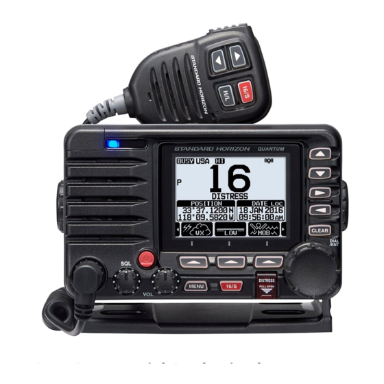
QUANTUM AIS GX6000
25 Watt VHF/FM Marine Transceiver
Owner's Manual
Advertisement
Table of Contents

Related Manuals for Standard Horizon QUANTUM AIS GX6000


Summary of Contents for Standard Horizon QUANTUM AIS GX6000
- Page 1 QUANTUM AIS GX6000 25 Watt VHF/FM Marine Transceiver Owner’s Manual z Capable of connecting two optional wired RAM4 or one wired RAM4 and up to four Wireless RAM4W remote access microphones using SCU-30 wireless access point z Integrated NMEA 2000 interface supporting all PGNs for Navigation, GPS, AIS and DSC functions...
-
Page 2: Table Of Contents
TABLE OF CONTENTS Quick Reference Guide ........2 9 GPS OPERATION ........47 1 GENERAL INFORMATION ......3 DISPLAYING POSITION INFORMATION ....47 2 PACKING LIST ..........4 CHECKING GPS STATUS ......... 47 3 OPTIONAL ACCESSORIES ......4 GPS LOGGER OPERATION ........48 4 ONLINE WARRANTY REGISTRATION 10 DIGITAL SELECTIVE CALLING (DSC) .. - Page 3 TABLE OF CONTENTS 16.6 MULTI WATCH ............112 24.3 RECEIVER (for Voice and DSC) ......147 16.7 PRIORITY CHANNEL ..........112 24.4 RECEIVER (for AIS) ..........148 16.8 SUB CHANNEL ............112 24.5 NMEA INPUT/OUTPUT ..........148 16.9 CHANNEL NAME ............. 112 24.6 SCU-31 EXTERNAL GPS ANTENNA (Optional) ..
-
Page 4: Quick Reference Guide
uick efeRence uide The GX6000 is equipped with the E2O (Easy-To-Operate) menu system. Basic operation may be accomplished by following the procedure below: Press and hold the key to turn on or off the radio. The MODE/STATUS indicator indicates the status of the transceiver. ... -
Page 5: General Information
1 GENERAL INFORMATION The STANDARD HORIZON GX6000 Marine VHF/FM Marine transceiver is designed to be used in USA, International, and Canadian Marine bands. The GX6000 can be operated from 11 to 16 VDC and has a switchable RF output power of 1 watt or 25 watts. -
Page 6: Packing List
HORIZON website. PRODUCT SUPPORT INQUIRIES If you have any questions or comments regarding the use of the GX6000, you can visit the STANDARD HORIZON website to send an E-Mail or contact the Product Support team at (800) 767-2450 M-F 8:00-5:00 PST. -
Page 7: Getting Started
5 GETTING STARTED PROHIBITED COMMUNICATIONS The FCC prohibits the following communications: • False distress or emergency messages: • Messages to “any boat” except in emergencies and radio tests; • Messages to or from a vessel on land; • Transmission while on land; •... -
Page 8: Coaxial Cable
COAXIAL CABLE VHF antennas are connected to the transceiver by means of a coaxial cable – a shielded transmission line. Coaxial cable is specified by its diameter and construction. For runs less than 20 feet, RG-58/U, about 1/4 inch in diameter is a good choice. For runs over 20 feet but less than 50 feet, the larger RG-8X or RG-213/U should be used for cable runs over 50 feet RG-8X should be used. -
Page 9: Calling Another Vessel (Channel 16 Or 9)
8. Give your vessel’s description: length, design (power or sail), color and other distinguishing marks. The total transmission should not exceed 1 minute. 9. End the message by saying “OVER”. Release the microphone switch and listen. 10. If there is no answer, repeat the above procedure. If there is still no response, try another channel. -
Page 10: Making Telephone Calls
After a transmission, say “over,” and release the microphone’s push-to-talk (PTT) switch. When all communication with the other vessel is completed, end the last transmission by stating your Call Sign and the word “out.” Note that it is not necessary to state your Call Sign with each transmission, only at the beginning and end of the contact. -
Page 11: What Is The Range For Ais Receivers
West Coast Sea Tow Newport/LA - Ch. 27 Sea Tow San Diego - Ch. 27 Northeast Sea Tow Portland-Midcoast (Maine) - Ch. 27 Sea Tow Boston - Ch. 27 Sea Tow South Shore (Mass.) - Ch. 28 Sea Tow Rhode Island - Ch. 24 Sea Tow Eastern Long Island - Ch. -
Page 12: Controls And Indicators
6 CONTROLS AND INDICATORS This section defines each control of the transceiver. See illustration below for location of controls. For detailed operating instructions refer to chapter 8 of this manual. FRONT PANEL ... - Page 13 MENU key Press to access MENU. For details, refer to section “8.4 BASIC OPERA- TION OF THE MENU MODE”. 16/S key Pressing this key immediately recalls channel 16 from any channel loca- tion. Holding down this key selects the SUB channel (The default setting is channel 9).
-
Page 14: Microphone
MODE/STATUS indicator Indicates the radio status with the four colors on the three positions of the mode/status indicator. Position Color Description Blue AIS-Board Working Purple Receiving MSG23 Left AIS-Board Failed Green AIS Receiving (registered MMSI) Orange AIS Receiving (unregistered MMSI) Right Receive Error DATA jack... - Page 15 When an optional RAM4 and RAM4W mic is connected and intercom mode is selected, pressing the PTT switch enables voice communications from the GX6000 to the RAM4 and RAM4W second station microphone. Microphone speaker Audio heard through internal radio speaker is heard through the speaker microphone.
-
Page 16: Rear Panel
50 ohms. PA Speaker Connection Cable (Orange, Yellow, Green & Blue) Connects the GX6000 to PA speakers. See section “3 OPTIONAL ACCES- SORIES” for a list of optional STANDARD HORIZON Speakers. Green: PA1 Speaker (+) Blue: PA1 Speaker (−) Orange: PA2 Speaker (+) Yellow: PA2 Speaker (−) - Page 17 RAM-1* / RAM-2 Remote Access Microphone Connectors Connects the GX6000 to the SSM-70H (RAM4) Remote Station Micro- phone or SCU-30 Wireless Access Point* for use with up to four SSM-71H (RAM4W) wireless microphones. Refer to section “19 SSM-70H (RAM4) REMOTE MIC OPERATION”...
-
Page 18: Installation
7 INSTALLATION SAFETY / WARNING INFORMATION This radio is restricted to occupational use, work related operations only where the radio operator must have the knowledge to control the exposure conditions of its passengers and bystanders by maintaining the minimum separation distance of 3 feet (1 m). - Page 19 Desktop Mounting Overhead Mounting 7.3.2 Optional MMB-84 Flush Mount Bracket 1. Use the template (page 153) to mark the location where the rectangular hole is to be cut. Confirm the space behind the dash or panel is deep enough to accommodate the transceiver (at least 6.7” (17 cm) deep). There should be at least 1/2”...
-
Page 20: Electrical Connections
ELECTRICAL CONNECTIONS CAUTION Reverse polarity battery connections will damage the radio! Connect the power cord and antenna to the radio. Antenna and Power Supply connections are as follows: 1. Mount the antenna at least 3 feet (1 m) away from the radio. At the rear of the radio, connect the antenna cable. -
Page 21: Connection Of External Devices
Ferrite Core (Large) Snap together Speaker Code DC Power Code Snap together Ferrite Core (Small) As close as possible Fuse Replacement To take out the fuse from the fuse holder, hold both ends of the fuse holder and pull the fuse holder apart without bending the fuse holder. - Page 22 • If 4800 baud (default) is selected: The Blue and Green wires of input are at 4800 baud. • If 38400 baud is selected: The Blue and Green wires of input are at 38400 baud. NMEA Output (DSC and GPS information) •...
- Page 23 7.5.4 NMEA 0813/NMEA 0183-HS to Chart Plotter 4800 Baud Connections External GPS Antenna SCU-31 (optional) Radio Wires Plotter Connection GPS Chart Plotter Blue: NMEA IN ( + ) No Connection Green: NMEA IN ( − ) No Connection Gray: NMEA OUT ( + ) NMEA IN ( + ) Brown: NMEA OUT ( −...
- Page 24 7.5.5 Connection to External GPS or Chart Plotter 4800 Baud Connections Radio Wires Plotter Connection GPS Receiver Blue: NMEA IN ( + ) NMEA OUT ( + ) Green: NMEA IN ( − ) NMEA OUT ( − ) Gray: NMEA OUT ( + ) NMEA IN ( + ) Brown: NMEA OUT ( −...
- Page 25 7.5.6 Connection to External PA/HAIL Speaker GREEN PA 1 Speaker (horn) BLUE ORANGE PA 2 Speaker (horn) YELLOW External Speaker WHITE Wire Color/Description Connection Examples RED - External Speaker (+) Positive wire of external 4 Ohm External speaker WHITE - External Speaker (−) Negative wire of external 4 Ohm External speaker GREEN - PA1 Speaker (+) Positive wire of external 4 Ohm audio speaker (horn)
- Page 26 7.5.8 Optional SSM-70H (RAM4) Installation The GX6000 is capable of using two SSM-70H (RAM4) Remote Station Microphones to remotely control the Radio, AIS, DSC and PA/Fog functions. In addition the GX6000 can operate as a full function intercom system between the SSM-70H (RAM4) and the GX6000.
- Page 27 4. Finally, wind some plastic tape around each ferrite core, to prevent vibration from causing the two halves to split apart. 5. Referring to illustration right, make a 1.2” (30 mm) hole in the wall, then insert the extension cable External Speaker Connections into this hole.
-
Page 28: Initial Setup Required When Turning
5. Rotate the DIAL/ENT knob to select “INTERNAL” or “EXTERNAL”, then press the [SELECT] soft key. 6. Press the CLEAR/ key to return to radio operation. 7.5.9 Optional SCU-30 Wireless Access Point Installation The GX6000 is capable of using a SSM-71H (RAM4W) Wireless Remote Station Microphone to remotely control the Radio, AIS, DSC and PA/Fog functions. - Page 29 WARNING The MMSI can be inputted only once, please be careful not to input the incorrect MMSI number. If you need to change the MMSI number after it has been entered, the radio will have to be returned to Factory Service.
-
Page 30: Checking Gps Signal (Gps Status Display)
CHECKING GPS SIGNAL (GPS STATUS DISPLAY) When the GX6000 receives the GPS signal from the optional SCU-31, a small satellite icon “ ” will appear on the display and your current location (latitude/ longitude) is shown on the display. (*When the GPS signal receiving from the NMEA 2000 or NEMA-0183, a “2K”... -
Page 31: Gps Configuration
GPS CONFIGURATION 7.8.1 Changing the GPS Time The GX6000 shows GPS satellite time or UTC (Universal Time Coordinated) time in factory default. A time offset is needed to show the local time in your area. The time offset must be changed in order for the radio to display the current time in your area. - Page 32 4. Rotate the DIAL/ENT knob to select “TIME AREA”, then press the [SELECT] soft key. 5. Rotate the DIAL/ENT knob to select “UTC” or “LOCAL”. 6. Press the [ENTER] soft key to store the selected setting. 7. Press the CLEAR key to return to radio operation. 7.8.3 Changing the Time Format This menu selection allows the radio to setup to show time in 12-hour or...
- Page 33 7.8.4 Changing COG to True or Magnetic Allows the GPS COG (Course Over Ground) and the BRG from an AIS target to be selected to show in ON or OFF. Factory default is “OFF” however by following the steps below the COG can be changed to “ON”. 1.
-
Page 34: Basic Operation
8 BASIC OPERATION TURNING ON AND OFF THE TRANSCEIVER 1. After the transceiver has been installed, ensure that the power supply and antenna are properly connected. 2. Press and hold the key to turn the radio on. 3. Press and hold the key again to turn the radio off. -
Page 35: Basic Operation Of The Menu Mode
8.3.1 Transmit Power The TX output power of the GX6000 is set to high level (25W) in factory default, and the “[HI]” indicator is displayed on the top part of the screen. To switch the TX output power: 1. Press the ►/◄ key repeatedly until the [HI] or [LOW] soft key is displayed at the bottom of the screen. -
Page 36: Transmit Time-Out Timer (Tot)
5. Rotate the DIAL/ENT knob or press the ▲/▼ key to select the desired setting. 6. Press the [ENTER] soft key to or press the DIAL/ENT knob store the selected setting. 7. Press the CLEAR key to return to radio operation. (The display can also be returned to the previous screen by pressing the [BACK] soft key.) The same operation process as the above is written as follows in this opera-... -
Page 37: Usa, International, And Canada Mode
USA, INTERNATIONAL, AND CANADA MODE To change the channel group from USA to International or Canada: 1. Press the MENU key to display “MENU”. 2. Rotate the DIAL/ENT knob to select “SETUP”, then press the [SELECT] soft key. 3. Rotate the DIAL/ENT knob to select “CHANNEL SETUP”, then press the [SELECT] soft key. - Page 38 8.8.1 NOAA Weather Alert In the event of extreme weather disturbances, such as storms and hurricanes, the NOAA (National Oceanic and Atmospheric Administration) sends a weather alert accompanied by a 1050 Hz tone and subsequent weather report on one of the NOAA weather channels. The GX6000 can receive weather alerts when monitoring a weather channel and, on the last selected weather channel during scanning modes or while on another working channel.
-
Page 39: Multi Watch (To Priority Channel)
MULTI WATCH (TO PRIORITY CHANNEL) Multi watch is used to scan two or three channels for communications. • In Dual Watch, a normal VHF channel and the priority channel are scanned alternately. • In Triple Watch, a normal VHF channel, the priority channel, and the sub channel are scanned alternately. -
Page 40: Scanning
8.10 SCANNING The GX6000 will automatically scan channels programmed into the preset channel memory and also the scan channel memory, and the last selected weather channel. When an incoming signal is detected on one of the channels during scan, the radio will pause on that channel, allowing you to listen to the incoming transmis- sion. - Page 41 To check channels to be scanned, rotate the DIAL/ENT knob. The “[MEM]” icon will appear when the memory channel is displayed. Note: When “SCAN MEMORY” is assigned to the soft key, the memory function switches between on and off every time you press the [MEM] soft key. 8.10.3 Memory Scanning (M-SCAN) 1.
-
Page 42: Preset Channels: Instant Access
8.11 PRESET CHANNELS: INSTANT ACCESS 10 preset channels can be programmed for instant access. Press the ►/◄ key repeatedly, then press the [PRESET] soft key. Pressing the [PRESET] key activates the user assigned channel bank. If the [PRESET] soft key is pressed and no channels have been assigned, alert beep will sound. -
Page 43: Mob Operation
8.11.3 Deletion 1. Press the ►/◄ key repeatedly, then press the [PRESET] soft key to recall the preset channel. 2. Rotate the DIAL/ENT knob to select the preset chan- nel to be deleted. 3. Press and hold the [PRESET] soft key until the “[P-SET]”... -
Page 44: Pa/Fog Operation
The GX6000 has two 25 W hailers built-in and can be used with any 4 Ohm PA horn. Standard Horizon offers two HAIL/PA horns, the 220SW (5” round 30 Watt HAIL/PA horn) and the 240SW (5” x 8” rectangular 40 Watt HAIL/PA horn). - Page 45 4. To listen back, rotate the VOL knob. 5. Press the CLEAR key to return to radio operation. 8.13.2 Operating the FOG HORN mode The user can select the type of horn from “Underway”, “Stop”, “Sail”, “Towing”, “Aground” and “Anchor”. ] ...
- Page 46 TYPE PATTERN USAGE TOWING One 5-second blasts Vessel under tow (manned). fo ll ow ed by t hr ee 1 - s e c o n d b l a s t s Listen Back ( s e p a r a t e d b y 2 120s seconds) every 120 seconds.
-
Page 47: Intercom Operation
8.14 INTERCOM OPERATION The optional SSM-70H (RAM4) remote station microphone must be connected to perform intercom functions between the GX6000 and the SSM-70H (RAM4). NOTE When using the intercom function, connect one or two SSM-70H (RAM4) Remote Station Microphone to the GX6000. 8.14.1 Communication ] ... -
Page 48: Demo Mode
8.16 DEMO MODE This mode is used by Standard Horizon sales persons and dealers to demonstrate radio, DSC and AIS functions. Demo mode allows latitude, longitude and time to be entered to simulate radio displays. When the demo mode is enabled, the radio display will automatically switch from the NORMAL, COMPASS, WAYPOINT, AIS and GM displays. -
Page 49: Gps Operation
9 GPS OPERATION The GX6000 has the optional SCU-31 external GPS antenna to receive and display the position information. When the radio is connected to an external GPS device by the NMEA-0183 or NMEA2000, you may select the order of priority of the connection devices to be used when obtaining location informa- tion via the SETUP menu (Refer to section “18.1 ORDER OF PRIORITY”). -
Page 50: Gps Logger Operation
GPS LOGGER OPERATION The GX6000* includes a logger for position information that allows you to record your location at regular intervals. (* Requires optional SCU-31 GPS Receiver.) 1. Press the [LOGGER] soft key to turn the function on or off. The recording starts and the display returns to the ”... -
Page 51: Digital Selective Calling (Dsc)
10 DIGITAL SELECTIVE CALLING (DSC) 10.1 GENERAL WARNING This GX6000 is designed to generate a digital maritime distress and safety call to facilitate search and rescue. To be effective as a safety device, this equipment must be used only within communication range of a shore-based VHF marine channel 70 distress and safety watch system. -
Page 52: Dsc Distress Alert
10.2 DSC DISTRESS ALERT The GX6000 is capable of transmitting and receiving DSC distress messages to all DSC radios. Distress alert calls from the GX6000 include the latitude and longitude of the vessel when the external GPS unit is activated. 10.2.1 Transmitting a DSC Distress Alert NOTE... - Page 53 Transmitting a DSC Distress Alert with Nature of Distress The GX6000 is capable of transmitting a DSC distress alert with the following “Nature of Distress” categories: Undesignated, Fire/Explosion, Flooding, Collision, Grounding, Capsizing, Sinking, Adrift, Abandoning, Piracy, MOB. ] “DSC CALL” “DIST ALERT MSG” 2.
- Page 54 Pausing a DSC Distress Alert After a DSC distress call is transmitted, the DSC distress call is repeated every 4 minutes until the call is canceled by the user or until the radio is turned off and on again. The GX6000 has the capability to suspend (pause) the retransmitting of the distress call by the procedure below.
- Page 55 10.2.2 Receiving a DSC Distress Alert 1. When a DSC distress call is received, an emergency alarm sounds. 2. Press any key to stop the alarm. 3. Rotate the DIAL/ENT knob to show information on the vessel in distress. On the display you will notice 3 soft key selections. These selections are described below: [ACCEPT]: Press this key to accept the DSC distress call and to switch to Channel 16.
-
Page 56: All Ships Call
10.3 ALL SHIPS CALL The all ships call function allows contact to be established with DSC equipped vessels without having their MMSI in the individual calling directory. Also, priority for the call can be designated as “Safety” or “Urgency”. SAFETY Call: This type of call is used to transmit boating safety information to other vessels. - Page 57 7. Press the [QUIT] soft key to exit the all ships call menu. 10.3.2 Receiving an All Ships Call 1. When an all ships call is received, an emergency alarm will sound. The display shows the MMSI of the vessel transmit- ting the all ships call and the radio will change to the requested channel after 30 seconds (the default setting of “AUTO CHANNEL CHANGE”).
-
Page 58: Individual Call
10.4 INDIVIDUAL CALL This feature allows the GX6000 to contact another vessel with a DSC VHF radio and automatically switch the receiving radio to a desired communications channel. This feature is similar to calling a vessel on CH16 and requesting to go to another channel (switching to the channel is private between the two vessels). - Page 59 8. Rotate the DIAL/ENT knob to select “MMSI:”, then press the [SELECT] soft key. 9. Rotate the DIAL/ENT knob to scroll through numbers, 0-9. To enter the desired number and move one space to the right by pressing the [SELECT] soft key.
- Page 60 10.4.4 Transmitting an Individual Call This feature allows the user to contact another vessel with a DSC radio. This feature is similar to calling a vessel on CH16 and requesting to go to another channel. Individual Call using the Individual/Position Directory ] ...
- Page 61 Individual Call by Manually Entering an MMSI You may enter an MMSI number manually to contact without storing it in the individual directory. ] “DSC CALL” “INDIVIDUAL CALL” 2. Rotate the DIAL/ENT knob to select “MANUAL”, then press the [SELECT] soft key. 3.
- Page 62 10.4.5 Receiving an Individual Call When an individual DSC call is received, the radio will automatically respond (default setting) to the calling ship, and switch to the requested channel for voice communications. Refer to section “10.4.2 Setting up the Individual Call Reply”...
- Page 63 4. After accepting the call, press the [ABLE] soft key to switch to the requested channel. (To inform the vessel that you are unable to respond, press the [UNABLE] soft key.) 5. Press the [YES] soft key to send an acknowledge- ment.
-
Page 64: Group Call
MMSI numbers. The first digit of a group MMSI is always set to “0” by International rules. All Standard Horizon radios are preset so when programming a group MMSI the first digit is set to “0”. - Page 65 Second, Third and Fourth digits of the group MMSI as it denotes the area the ship is located in. The last 5 digits are decided upon by persons in the group. This is an impor- tant step as all radios in the group must contain the same group MMSI so they can be contacted by each other.
- Page 66 If a mistake was made entering in the MMSI number, rotate the DIAL/ENT knob to select “←” or “→”, press the [SELECT] soft key until the wrong character is selected, then perform step 9. 10. When finished entering the MMSI number, press the [FINISH] soft key to confirm. 11.
- Page 67 Group Call by Manually Entering an MMSI This feature allows you to contact a group of vessels by entering in their group MMSI manually. ] “DSC CALL” “GROUP CALL” 2. Rotate the DIAL/ENT knob to select “MANUAL”, then press the [SELECT] soft key.
- Page 68 10.5.3 Receiving a Group Call 1. When a group call is received, the GX6000 will produce a ringing alarm sound. 2. The display shows the group MMSI number. 3. Press any key to stop the alarm. On the display you will notice 3 soft key selections. These selections are described below: [ACCEPT]: Press this key to accept the group call and to switch to requested channel.
-
Page 69: Position Request
GX6000. Standard Horizon has taken this feature one step further, if a compatible GPS chart plotter is connected to the GX6000, the polled position of the vessel is shown on the display of the GPS chart plotter making it easy to navigate to the location of the polled vessel. - Page 70 3. Press the [ENTER] soft key to store the selected setting. 4. Press the CLEAR key to return to radio operation. 10.6.2 Transmitting a Position Request to Another Vessel Position Request using the Individual/Position Directory Refer to section “10.4 INDIVIDUAL CALL” to enter information into the indi- vidual directory.
- Page 71 2. Rotate the DIAL/ENT knob to select “MANUAL”, then press the [SELECT] soft key. 3. Rotate the DIAL/ENT knob to select the first number of the MMSI (nine digits) which you want to contact, then press the [SELECT] soft key to step to the next number.
- Page 72 4. Press the [QUIT] soft key to return to the channel display. NOTE When there is an unread position request call, “ ” icon will appear on the display. You may review the unread individual call from the DSC log, refer to the section “10.11.3 Reviewing Other Logged Calls”. 10.6.4 Manual Input of Position Information If the GX6000 is located in an area where GPS reception is limited when you...
-
Page 73: Position Report
10.6.5 Setting up a Position Request Ringer The GX6000 has the capability to turn off the position request ringer. ] “SETUP” “DSC SETUP” “DSC BEEP” 2. Rotate the DIAL/ENT knob to select “POS REQUEST”, then press the [SELECT] soft key. 3. - Page 74 4. If you want to change the position displayed, press the [POS/TM] soft key to go to the position information input screen. After inputting new position information, press the [FINISH] soft key to confirm. 5. Press the [YES] soft key to send your position to the selected vessel. 6.
- Page 75 8. Press the [QUIT] soft key to return to radio operation. 10.7.2 Receiving a DSC Position Report Call When another vessel transmits their vessels location to the GX6000 the follow- ing will happen: 1. When a position report call is received from another vessel, a ringing sound will be produced.
- Page 76 3. The display indicates the distance and direction of the received vessel, and the compass displays the received vessel with a dot (). Stopping Navigation to the Reported Position 1. Press one of the soft keys to show the key selections. 2.
-
Page 77: Polling Call
Navigating to a Saved Waypoint Refer to section “11.1.1 Starting and Stopping Navigation” for details. 10.7.5 Setting up a Position Report Ringer The GX6000 has the capability to turn off the position report ringer. ] “SETUP” “DSC SETUP” “DSC BEEP” 2. - Page 78 4. Press the [YES] soft key to transmit the polling call. 5. After a polling call is transmitted, if the reply signal is not received, “Waiting for ACK” is shown on the display which means the GX6000 is waiting for the vessel you called to send an acknowledgement.
-
Page 79: Auto Position Polling
10.8.2 Receiving a Polling Call When another vessel transmits a polling call to the GX6000 the following will happen: 1. When a polling call is received, the radio will automati- cally respond to the calling vessel. 2. To exit from the polling call display, press the [QUIT] soft key. - Page 80 10.9.3 Selecting Vessels to be Automatically Polled NOTE The radio uses the individual directory to select vessels to be auto- matically polled. Refer to section “10.4.1 Setting up the Individual / Position Call Directory” and to enter MMSI of vessels you want to poll before proceeding.
-
Page 81: Dsc Test
4. Press the CLEAR key to return to radio operation. 5. Auto POS Polling starts and “[A]” icon will light up on the screen. 10.10 DSC TEST This function is used to contact another DSC equipped vessel to ensure the DSC functions of the radio are operating. - Page 82 DSC Test Call by Manually Entering an MMSI ] “DSC CALL” “DSC TEST CALL” “MANUAL” 2. Rotate the DIAL/ENT knob to select “MANUAL”, then press the [SELECT] soft key. 3. Rotate the DIAL/ENT knob to select the first digit in the MMSI, then press the [SELECT] soft key.
-
Page 83: Dsc Log Operation
10.11 DSC LOG OPERATION The GX6000 logs transmitted calls, received DSC distress calls, and other calls (individual, group, all ships, etc.). The DSC log feature is similar to an answer machine where calls are recorded for review and a “ ”... - Page 84 10.11.2 Reviewing a Logged DSC RX Distress Call The GX6000 allows logged DSC RX distress call to be reviewed. ] “DSC CALL” “DSC LOG” “RX DISTRESS” 2. Rotate the DIAL/ENT knob to select the station (name or MMSI number) you want to review and/or relay the distress call to other vessels.
-
Page 85: Dsc Loop Back Operation
2. Rotate the DIAL/ENT knob to select the category (“TRANSMITTED”, “RX DISTRESS”, “RX OTHER CALL” or “ALL LOG”) to be deleted. 3. Press the [SELECT] soft key. The display will show “Do you want to delete the LOG?”. 4. Press the [YES] soft key. (To cancel, press the [NO] soft key.) 5. -
Page 86: Navigation
11 NAVIGATION The GX6000 is capable of storing up to 250 waypoints for navigation using the compass page. You can also navigate to DSC distress calls with position or a position received from another DSC radio using DSC polling. 11.1 WAYPOINT OPERATION 11.1.1 Starting and Stopping Navigation... - Page 87 4. Rotate the DIAL/ENT knob to select “POSITION:”, then press the [SELECT] soft key. 5. Rotate the DIAL/ENT knob to select the first number of latitude, then press the [SELECT] soft key to step to the next number. 6. Repeat step 5 to set the position. If a mistake was made, rotate the DIAL/ENT knob to select “←”...
- Page 88 4. If you want to modify the position, rotate the DIAL/ENT knob to select “POSITION:”, press the [SELECT] soft key, then enter the new coordinates. When finished modifying the position, press the [FINISH] soft key. 5. Rotate the DIAL/ENT knob to select “SAVE”, then press the [SELECT] soft key to save the mark posi- tion into memory.
- Page 89 3. Rotate the DIAL/ENT knob to select the waypoint to be edited, then press the [SELECT] soft key to show the waypoint input display. 4. Rotate the DIAL/ENT knob to select “NAME:” or “POSITION:”, then press the [SELECT] soft key. 5.
-
Page 90: Routing Operation
11.1.3 Selecting the Display Range This menu item allows setting of the range on the compass display. ] “SETUP” “WAYPOINT SETUP” “DISPLAY RANGE” 2. Rotate the DIAL/ENT knob to select desired range. (Unit of measure depends on the settings in the GPS SETUP menu. - Page 91 Adding a Route ] “SETUP” “WAYPOINT SETUP” “ROUTE DIRECTORY” 2. Rotate the DIAL/ENT knob to select “ADD”, then press the [SELECT] soft key. 3. Rotate the DIAL/ENT knob to select “NAME:”, then press the [SELECT] soft key. 4.
- Page 92 2. Rotate the DIAL/ENT knob to select “EDIT”, then press the [SELECT] soft key. 3. Rotate the DIAL/ENT knob to select the route to be edited, then press the [SELECT] soft key to show the route input display. 4. Perform steps 3 to 11 of the previous page until the route is updated.
- Page 93 3. Rotate the DIAL/ENT knob to select a route, then press the [SELECT] soft key. The navigation screen with “RUT” indicator appears. 4. A message “ARRIVED” will appear when you have reached to the first target point. To start navigation to the next target, press the [YES] soft key.
-
Page 94: Gm Operation
12 GM OPERATION The GM (Group Monitor) feature of the GX6000 utilizes the same system as the DSC Group call and Auto Position Polling, to display the group members' locations. 12.1 SETTING UP GM OPERATION The GX6000 is capable of storing up to 10 groups with 1 to 9 members each. 12.1.1 Setting Up GM Group Directory NOTE... - Page 95 7. Rotate the DIAL/ENT knob to select a list number, then press the [SELECT] soft key. 8. Rotate the DIAL/ENT knob to select a member from the Individual directory, then press the [SELECT] soft key. 9. Repeat steps 8 to add members to the group, then press the [BACK] soft key.
-
Page 96: Starting Gm Operation
12.2 STARTING GM OPERATION NOTE To start GM operation, configure the GM Group Directory setting in setup menu. Otherwise, you cannot start the GM operation. Refer to section “12.1.1 Setting Up GM Group Directory” for details. ] “GM” 2. Rotate the DIAL/ENT knob to select the desired category (“HISTORY”... - Page 97 The GM group being monitored changes. The GM target display appears. 5. Press the CLEAR key to return to radio operation. 12.2.2 Transmitting a DSC Call to a Group Member 1. On the GM target display, press one of the soft keys to show the key selections.
-
Page 98: Automatic Identification System (Ais)
13 AUTOMATIC IDENTIFICATION SYSTEM (AIS) 13.1 GENERAL NOTE • The GX6000 is equipped with an antenna connection designated for AIS. By connecting a marine antenna to this connector, the transceiver can receive AIS signals while receiving a VHF voice transmissions. •... -
Page 99: Ais Operation
13.2 AIS OPERATION The GX6000 is equipped with an AIS receiver and can display AIS targets around your vessel on the radio's display. Therefore, you can identify and avoid in proximity to your vessel. NOTE To show AIS targets on the radio’s display, the optional SCU-31 or an external GPS devices needs to be connected via NMEA 0183 or NMEA 2000 so the radio knows its position relative to the AIS targets. - Page 100 3. Rotate the DIAL/ENT knob to select the MMSI number (or vessel name). then press the [SELECT] soft key. Pressing the [DANGER] soft key changes the order to the TCPA time order. 4. The AIS target information screen appears. To see more information of the AIS target, press the [NEXT] soft key.
- Page 101 4. Press the [CALL] soft key 5. In the INTERSHIP CH list, rotate the DIAL/ENT knob to select the operating channel on which you want to communicate, then press the [SELECT] soft key. To select operating channels from all voice channels, press the [MANUAL] soft key.
-
Page 102: Ais Setup
3. On the display you will notice 3 soft key selections. These selections are described below: [INFO]: Pressing this key shows the information screen of the CPA/TCPA alarm targets. [CALL]: Pressing this key switches the screen to the setting screen for transmitting individual DSC calls. - Page 103 ] “SETUP” “AIS SETUP” “TCPA” 2. Rotate the DIAL/ENT knob to select the time you want the radio to alert you of an approaching AIS equipped vessel. The time can be set from “1min” to “30min” (“10min” is default). 3.
-
Page 104: Nmea 2000 Setup
14 NMEA 2000 SETUP Set the device numbers and system numbers of devices connected to the NMEA 2000 network. 14.1 SELECT DEVICE Select the device for which you want to set the device number and system number. ] “SETUP” “NMEA2000 SETUP” “SELECT DEVICE” 2. -
Page 105: System Number
14.3 SYSTEM NUMBER Set the system number of the device selected in “14.1 SELECT DEVICE”. ] “SETUP” “NMEA2000 SETUP” “SYSTEM NUMBER” 2. Rotate the DIAL/ENT knob to select the first digit of the system number, then press the [SELECT] soft key to step to the next number. - Page 106 Receive Transmit 129029 GNSS Position Data 129029 GNSS Position Data 129033 Local Time Offset − − − − 129038 AIS Class A Position Report − − 129039 AIS Class B Position Report 129040 AIS Class B Extended Position − − Report 129041 AIS Aids to Navigation (AtoN)
-
Page 107: Configuration Setup
15 CONFIGURATION SETUP 15.1 DISPLAY MODE The display mode can be selected according to the time of day you operate the radio. ] “SETUP” “CONFIGURATION” “DISPLAY MODE” 2. Rotate the DIAL/ENT knob to select the desired setting. You can select one from “DAY MODE” or “NIGHT MODE”. -
Page 108: Key Beep
15.4 KEY BEEP This selection is used to select the beep tone volume level when a key is pressed. ] “SETUP” “CONFIGURATION” “KEY BEEP” 2. Rotate the DIAL/ENT knob to select the desired level. The beep level can be set from “1” to “7”, or “OFF” (“4”... -
Page 109: Station Name
2. Rotate the DIAL/ENT knob to select “OFF” or “ON” (“ON” is default). 3. Press the [ENTER] soft key to store the selected setting. 4. Press the CLEAR key to return to radio operation. 15.7 STATION NAME This function allows you to change the name of the radio or second station microphone. -
Page 110: Soft Keys
10. Repeat steps 8 and 9 until the name is complete. The name can consist of up to ten characters, and if you do not use all ten characters, select “→” to move to the next space. This method can also be used to enter a blank space in the name. - Page 111 SOFT KEY NUMBERS DISPLAY FUNCTION ASSIGNED AS DEFAULT (See the previous page.) NONE − TX HI/LO Selects transmit power WX/CH Switches channels between weather and marine SCAN Turns on or off scanning function DUAL WATCH / Starts and stops dual watch scan TRIPLE WATCH MARK POSITION Marks the current position for a “Waypoint”...
-
Page 112: Reset
15.9 RESET You may reset the memory and settings of the setup categories independently or return the transceiver to the original factory setting. ] “SETUP” “CONFIGURATION” “RESET” 2. Rotate the DIAL/ENT knob to select the desired category. You can select one from “DSC/GM SETUP”, “WAYPOINT SETUP”, “CHANNEL SETUP”, “GPS SETUP”, “AIS SETUP”, “CONFIGURATION”, or “FACTORY”... -
Page 113: Channel Function Setup
16 CHANNEL FUNCTION SETUP 16.1 CHANNEL GROUP This menu item allows you to select a channel group from USA, Canada, and International. Refer to section “8.7 USA, INTERNATIONAL, AND CANADA MODE” for details. 16.2 WEATHER ALERT Enables/disables the NOAA Weather Alert function. The default setting is “ON”. ] ... -
Page 114: Multi Watch
16.6 MULTI WATCH This selection is used to select the watch type between “DUAL” and “TRIPLE”. The default setting is “DUAL”. Refer to section “8.9 MULTI WATCH (TO PRIORITY CHANNEL)” for details. 16.7 PRIORITY CHANNEL This procedure allows the radio to use a different priority channel used when priority scanning. -
Page 115: Noise Cancellation
4. Press the [SELECT] soft key to store the first letter in the name and step to the next letter to the right. 5. Repeat step 3 and 4 until the name is complete. The name can consist of up to 16 characters, if you do not use all 16 characters, select “→”... -
Page 116: Audio Filter Operation
4. Rotate the DIAL/ENT knob to select “RX MODE”, then press the [SELECT] soft key. 5. Rotate the DIAL/ENT knob to select the noise level from “LEVEL1” through “LEVEL4” or “OFF”, then press the [ENTER] soft key. 6. Press the CLEAR key to return to radio operation. 16.11 AUDIO FILTER OPERATION This menu item allows you to select operation of the internal audio filter for the best acoustics in noisy environments. - Page 117 2. Rotate the DIAL/ENT knob to select “RECORDING DELAY TIME”, then press the [SELECT] soft key. 3. Rotate the DIAL/ENT knob to select the desired delay time. The delay time can be set to “1sec” through “5sec”. 4. Press the [ENTER] soft key to store the new setting. 5.
-
Page 118: Scrambler Setup
3. Press the [YES] soft key. (To cancel, press the [NO] soft key.) 4. Press the [OK] soft key. 5. Press the CLEAR key to return to radio operation. 16.13 SCRAMBLER SETUP Configure the voice scrambler setting. Two types of voice scrambler functions are available: the 4-code type (CVS2500A compatible) and the 32-code type (FVP-42 compatible for Furuno Electric FM-4721) (This function is not avail- able for CH16 and CH70). -
Page 119: Summary Of The Cannel Function Setup
6. Rotate the DIAL/ENT knob to select the scrambler code. The scrambler code can be set from “00” to “03” or “OFF” (While FVP-42 is selected in step 6, the scrambler code can be set from “00” to “31” or “OFF”). -
Page 120: Dsc Setup
17 DSC SETUP 17.1 INDIVIDUAL DIRECTORY The GX6000 has a DSC directory that allows you to store a vessel or person’s name and the associated MMSI you wish to contact via individual calls, position requests and position report transmissions. To transmit an individual call you program this directory with information of the vessel you wish to contact, similar to a cellular phone's telephone directory. -
Page 121: Position Reply
17.6 POSITION REPLY The GX6000 can be set up to automatically (default setting) or manually send your position when requested by another vessel. This selection is important if you are concerned about someone polling the position of your vessel that you may not want to. -
Page 122: No Action Timer
17.10 NO ACTION TIMER If no key is pressed during the “MENU” or “DSC CALL” screen, the GX6000 will automatically return to radio operation. The default selection is 15 minutes. ] “SETUP” “DSC SETUP” “NO ACTION TIMER” 2. - Page 123 Item Description Default Value Page GROUP DIRECTORY Enter or edit addresses used for − group call POSITION REPLY Selects reply mode when receiv- AUTO ing a position call AUTO POSITION Selects the AUTO POSITION AUTO POS REQUEST POLLING POLLING operation type AUTO POS INTERVAL Selects the transmission interval 30 sec...
-
Page 124: Gps Setup
18 GPS SETUP The “GPS Setup” mode allows the parameters for the NMEA2000 or the NMEA -0183 or the optional SCU-31 external GPS antenna to be customized for your operating requirements. 18.1 ORDER OF PRIORITY Specify the order of priority of the connection devices to be used when obtain- ing location information. -
Page 125: Time Offset
2. Rotate the DIAL/ENT knob to select the desired coor- dinate system. The location format can be selected from “ddd°mm.mmmm” and “ddd°mm’ss””. 3. Press the [ENTER] soft key to save the new setting. 4. Press the CLEAR key to return to radio operation. 18.4 TIME OFFSET Sets the local time offset between UTC (Universal Time Coordinated) and local... -
Page 126: Nmea 0183 In/Out
18.9 NMEA 0183 IN/OUT 18.9.1 Data Speed This menu is used to setup the NMEA 0183 baud rate of the GPS input (Blue and Green wires) and DSC output (Gray and Brown wires). The default setting is 4800 bps. When 38400 bps is selected the AIS sentences (VDM) and DSC sentences (DSC &... -
Page 127: Position Data Output
4. Rotate the DIAL/ENT knob to select “ON” or “OFF”. 5. Press the [ENTER] soft key to save the new setting. 6. Repeat steps 3 through 5 to set the other sentences. 7. Press the CLEAR key to return to radio operation. NOTE •... -
Page 128: Option Gps Unit
18.11 OPTION GPS UNIT Change the optional GPS Antenna (SCU-31) setting. 18.11.1 Unit Power When you use the SCU-31, set this selection to “ON”. The default setting is “OFF”. ] “SETUP” “GPS SETUP” “OPTION GPS UNIT” 2. Rotate the DIAL/ENT knob to select “UNIT POWER”, then press the [SELECT] soft key. - Page 129 18.11.3 Differential GPS This selection enables or disables differential GPS function by SBAS (Satellite Based Augmentation System) such as WAAS, EGNOS and MSAS. In some areas (Australia for example), the GPS reception can have problems on enabling the SBAS. The default setting is “OFF”. ] ...
-
Page 130: Summary Of The Gps Setup
18.11.5 Log Erase ] “SETUP” “GPS SETUP” “OPTION GPS UNIT” 2. Rotate the DIAL/ENT knob to select “LOG ERASE”, then press the [SELECT] soft key. 3. Press the [YES] soft key. (To cancel, press the [NO] soft key.) 4. - Page 131 Item Description Default Value Page OUTPUT SENTENCES Enables/disables NMEA sentences GLL: ON GGA: ON GSA: ON GSV: ON RMC: ON DSC/DSE: ON POS DATA OUTPUT Selects the connection device NMEA 2000: OFF when outputting position data NMEA-0183: OFF OPTION GPS UNIT UNIT POWER Enables/disables the OPTION GPS UNIT...
-
Page 132: Ssm-70H ( Ram4 ) Remote Mic Operation
19 SSM-70H ( RAM4 ) REMOTE MIC OPERATION When a remote microphone is connected to the GX6000, all VHF, DSC, setup menus, AIS, Navigation, GM (Group Monitor) functions and PA/Fog modes can be remotely operated. The SSM-70H’s operation is same as GX6000 except the receiver audio volume setting and squelch level setting. - Page 133 econdary uSe Press this knob to enter a selection in the MENU. SQL key (Squelch control) Press this key to activate the squelch adjusting mode. Press the CH▲ or CH▼ key to adjust the squelch threshold level. PTT (Push-To-Talk) switch Push this switch to enable the transmitter.
-
Page 134: Ram4 Soft Key Assignment
16/S key Pressing this key immediately recalls channel 16 from any channel location. Holding down this key recalls the SUB channel (The default setting is channel 9). Pressing this key again reverts to the previous selected working channel. Speaker The internal speaker is located here. DATA jack Use the micro USB type B jack for SSM-70H (RAM4) firmware updates. - Page 135 NOTE You can assign functions to soft keys on each of the transceiver and the optional SSM-70H (RAM4) remote mic. 19.2.1 Key Assignment Configure all settings on the SSM-70H (RAM4) remote mic for which you want to assign functions to soft keys. ] ...
-
Page 136: Connecting A Usb Data Terminal
The GX6000 settings can be programmed using the USB terminal and PC Programming Software. You can also download the log data from the radio by using the PC Programming Software which may be downloaded from the Standard Horizon website. The PC Programming Software is compatible with Windows ®... -
Page 137: Maintenance
11 VDC. • Use only STANDARD HORIZON approved accessories and replacement parts. In the unlikely event of serious problems, please contact your Dealer or our repair facility. Address and phone numbers for this facility, as well as warranty information, are contained in section “23 WARRANTY”. -
Page 138: Factory Service
21.2 FACTORY SERVICE In the unlikely event that the radio fails to perform or needs servicing, please contact the following: Standard Horizon Attention Marine Repair Department 6125 Phyllis Drive, Cypress, California 90630, U.S.A. Telephone (800) 366-4566 For repairs in Canada... -
Page 139: Troubleshooting Chart
21.3 TROUBLESHOOTING CHART SYMPTOM PROBABLE CAUSE REMEDY Transceiver fails to No DC voltage to the a. Check the 12VDC battery connections power up. transceiver, or blown fuse. and the fuse. b. The key needs to be pressed and held to turn the radio on. T r a n s c e i v e r Reversed power wires. -
Page 140: Channel Assignments
22 CHANNEL ASSIGNMENTS Tables on the following columns list the VHF Marine Channel assignments for U.S.A. and International use. Below are listed some data about the charts. 1. VTS. Where indicated, these channels are part of the U.S. Coast Guard’s Vessel Traffic System. - Page 141 6. Marine vessels equipped with VHF radios are required to monitor Channel 7. 156.050 MHz and 156.175 MHz are available for port operations and commercial communications purposes when used only within the U.S. Coast Guard designated Vessel Traffic Services (VTS) area of New Orleans, on the lower Mississippi River from the various pass entrances in the Gulf of Mexico to Devil’s Swamp Light at River Mile 242.4 above head of passes near Baton Rouge.
- Page 142 west Pass entrance Mid channel Lighted Whistle Buoy to mile 242.4 above head of Passes near Baton Rouge, and in addition over the full length of the Mississippi River-Gulf Outlet Canal from entrance to its junction with the Inner Harbor Navigation Canal, and over the full length of the Inner Harbor Navigation Canal from its junction with the Mississippi River to its entry to Lake Pontchartrain at the New Seabrook vehicular bridge.
- Page 143 VHF MARINE CHANNEL CHART CHANNEL USE 160.650 Public Correspondence ( Marine Operator ) 156.050 Port Operation and Commercial. 1001 156.050 VTS in selected areas 160.700 Public Correspondence ( Marine Operator ) 156.100 160.750 Public Correspondence ( Marine Operator ) 156.150 1003 U.S.
- Page 144 VHF MARINE CHANNEL CHART CHANNEL USE 161.750 Public Correspondence ( Marine Operator ) 157.150 1023 157.150 U.S. Government Only 2023 - - - 161.750 CMB Service 161.800 Public Correspondence ( Marine Operator ) 157.200 161.850 Public Correspondence ( Marine Operator ) 157.250 2025 - - -...
- Page 145 VHF MARINE CHANNEL CHART CHANNEL USE US: Port Operations, Canada: Commercial fishing only, 156.725 International: Inter-ship, Port operations and Ship movement Port Operations ( Inter-ship only ) ( 1 W ) 156.775 Port Operations ( Inter-ship only ) ( 1 W ) 156.825 Port Operations ( Inter-ship only ) ( 1 W ) 156.875...
-
Page 146: Warranty
STANDARD HORIZON will return the Product to the purchaser freight prepaid. Products purchased prior to January 1, 1991 will bear the STANDARD HORIZON warranty terms in effect prior to that date. In the event of a defect, malfunction or failure of the Product during the warranty period, STANDARD HORIZON’s liability for any breach of contract or any... - Page 147 STANDARD HORIZON, appear to be defective or not up to factory specifications. STANDARD HORIZON may, at its option, repair or replace parts or subassemblies with new or reconditioned parts and subassemblies. Parts thus repaired or replaced are warranted for the balance of the original applicable warranty.
- Page 148 STANDARD HORIZON. Lifetime Flat Rate Service Program: For the original Owner only, for the lifetime of the unit, STANDARD HORIZON will repair the unit to original specifications. Note: The flat rate amount is payable by the Owner only if STANDARD HORIZON or the STANDARD HORIZON Dealer determines that a repair is needed.
-
Page 149: Specifications
24 SPECIFICATIONS Performance specifications are nominal, unless otherwise indicated, and are subject to change without notice. Measured in accordance with TIA/EIA-603. 24.1 GENERAL Channels ............All USA, International and Canadian Normal Input Voltage ................... 13.8 V DC Operating Voltage Range ..............11 V to 16.5 V Current Drain Standby ...................... -
Page 150: Receiver (For Ais)
Frequency Stability ............±0.0003 % (–20°C to +60°C) Channel Spacing ....................25 kHz DSC Format ..................ITU-R M.493-13 Attenuator (Local) .................. Approx. 10 dB 24.4 RECEIVER (for AIS) Frequency ..........161.975 MHz (CH A), 162.025 MHz (CH B) Sensitivity ................0.5 µV (at 12 dB SINAD) Selectivity(Typical) Spurious and Image Rejection .............. -
Page 151: Dimensions
24.7 DIMENSIONS 6.2" ( 155.4 mm ) 6" ( 152.4 mm ) 1" ( 26.3 mm ) 5.7" ( 147 mm ) 4.3" ( 108 mm ) 6.9" ( 175.5 mm ) 1.8" ( 45.4 mm ) 1.9" ( 48.5 mm ) 6.1"... -
Page 152: Fcc Radio License Information
25 FCC RADIO LICENSE INFORMATION Standard Horizon radios comply with the Federal Communication Commission (FCC) requirements that regulate the Maritime Radio Service. 25.1 STATION LICENSE An FCC ship station license is no longer required for any vessel traveling in U.S. waters (except Hawaii) which is under 20 meters in length. However, any... -
Page 153: Fcc Notice
NOTICE Unauthorized changes or modifications to this equipment may void compliance with FCC Rules. Any change or modification must be approved in writing by STANDARD HORIZON. NOTICE This equipment has been tested and found to comply with the limits for a Class B digital device, pursuant to Part 15 of the FCC Rules. - Page 154 THIS DEVICE COMPLIES WITH PART 15 OF THE FCC RULES. OPERATION IS SUBJECT TO THE FOLLOWING TWO CONDITIONS: (1) THIS DEVICE MAY NOT CAUSE HARMFUL INTERFERENCE, AND (2) THIS DEVICE MUST ACCEPT ANY INTERFERENCE RECEIVED, INCLUDING INTERFERENCE THAT MAY CAUSE UNDESIRED OPERATION.
-
Page 155: Template For The Gx6000
94 mm Page 153... - Page 158 Copyright 2018 YAESU MUSEN CO., LTD. All rights reserved. No portion of this manual may be reproduced without the permission of YAESU MUSEN CO., LTD. YAESU U.S.A. 6125 Phyllis Drive, Cypress, California 90630 www.standardhorizon.com 1805-B...
Need help?
Do you have a question about the QUANTUM AIS GX6000 and is the answer not in the manual?
Questions and answers