Moxa Technologies TC-6110-W7E Quick Installation Manual
Tc-6110 series.
train computer
Hide thumbs
Also See for TC-6110-W7E:
- Quick installation manual (2 pages) ,
- Quick installation manual (8 pages) ,
- Hardware manual (46 pages)
Table of Contents
Advertisement
Quick Links
TC-6110 Series
Train Computer
Quick Installation Guide
Second Edition, May 2013
1. Overview
TC-6110 train computers are specifically designed for onboard
train applications. They come with 2 Gigabit LAN ports, 1 RS-232
serial port, 3 USB 2.0 hosts, and 2 expansion slots, offering an
ideal solution for any auxiliary train application.
To guarantee high reliability and availability during train
operations, TC-6110 computers come with M12 connectors for
Gigabit LAN ports, USB ports, and dual power inputs. In addition,
the expansion modules offer high flexibility for system integration.
Users can easily expand the system with additional storage
modules for greater storage capacity.
2. Model Names and Package Checklist
The TC-6110 Series includes the following models:
•
TC-6110-W7E: Modular 3U/42HP train computer, Intel Atom
D525 1.8GHz CPU, 4 expansion slots, 24 to 110 VDC isolated
power, Win7 Embedded (32-bit), -25 to 55°C operating
temperature range, compliant with EN 50155 T1
•
TC-6110-T-W7E: Modular 3U/42HP train computer, Intel
Atom D525 1.8GHz CPU, 4 expansion slots, 24 to 110 VDC
isolated power, Win7 Embedded (32-bit), -40 to 70°C
operating temperature range, compliant with EN 50155 TX
Each basic system model is shipped with following standard items:
•
TC-6110 train computer
•
Rackmount kit
•
Power switch with cable extender
•
Power cable
•
Documentation CD or DVD
•
Quick installation guide (printed)
•
Warranty card
P/N: 1802061100011
– 1 –
3. Hardware Installation
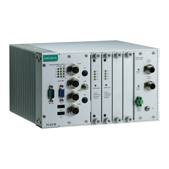
Front View
Front Panel LEDs
Information about each LED is given in the following table.
LED Name
LED Color
LED Function
Power
Green
Power is on and functioning normally
Off
Power is off or power system error
System
Yellow
Logged in to OS, functioning normally
Ready
Off
Login failure or OS not functioning normally
Tx (P1)
Green
Serial port P1 transmitting data
Off
Serial port P1 not transmitting data
Rx (P1)
Yellow
Serial port P1receving data
Off
Serial port P1 not receiving data
X1-X4
Green
Programmable by users
Off
Programmable by users
LAN (P1-P2) Green
Working 100 Mbps Ethernet link
Yellow
Working 1000 Mbps Ethernet link
Off
Disconnected or short circuit
Connecting to a Display
The TC-6110 comes with a female D-Sub DE-15 VGA interface on
the front panel. To ensure that the monitor image remains stable,
be sure to tighten the connector's thumbscrews after connecting
the cable.
Reset Button
The reset button on the TC-6110's front panel initiates a soft
system reboot. Once the system has completed the reboot the
Ready LED will maintain a steady glow.
Powering the TC-6110
TC-6110 computers come with DC power inputs. When connecting
the TC-6110 to an office AC source (for testing), an adaptor must
be used. To connect the AC adaptor, follow these steps:
Step 1: Connect the ends of the extended power switch cable to
the male portion of the 2-pin Euroblock (provided).
Step 2: Plug the male Euroblock into the matching female terminal
on the front panel.
– 2 –
Step 3: Make sure the power switch is turned off (Open, in the
diagram below).
Step 4: Connect the earth/ground cable to the Phillips-head
ground connector on the lower right corner of the front panel.
Step 5: Connect the power cable
(CBL-Power Jack to M12) to the M12
connector as shown at right. Then
connect the power connector to
power input 1 on the front panel.
Step 6: On the other side of the power cable, connect to the
PWR-24250-DT-S1 power adaptor (optional), and a PWC-series
power cord (optional).
Step 7: To check power redundancy, use the same method to
connect the power to the power input 2.
Step 8: Switch on the TC-6110 (Short state). If power supply is
connected properly, both power input and system power LEDs will
be on (green), as well as the yellow Ready LED.
When installing TC-6110 computers at a field site, follow these
steps:
Step 1: Connect the ends of the extended power switch cable to
the male portion of the 2-pin Euroblock (provided); you may also
choose to not use the cable extender, and connect the switch to
the terminal directly.
Step 2: Plug the male Euroblock into the matching female terminal
on the front panel.
Step 3: Make sure the power switch is turned off (Open).
– 3 –
Advertisement
Table of Contents

Related Manuals for Moxa Technologies TC-6110-W7E


Summary of Contents for Moxa Technologies TC-6110-W7E
- Page 1 The TC-6110 Series includes the following models: Rx (P1) Yellow Serial port P1receving data • TC-6110-W7E: Modular 3U/42HP train computer, Intel Atom Serial port P1 not receiving data D525 1.8GHz CPU, 4 expansion slots, 24 to 110 VDC isolated X1-X4 Green Programmable by users power, Win7 Embedded (32-bit), -25 to 55°C operating...
- Page 2 Step 4: Connect the earth/ground cable to the Phillips-head Serial Ports Step 1: Go to Start=>Control Panel=>Network and Internet=> Network Connections. ground connector on the lower right corner of the front panel. The TC-6110 comes with one DB-9 (male) RS-232 serial interface. The pin assignments for the ports are shown in the following table: Step 5: Connect the M12 connector to the Step 2: Go to the Local Area Connection tab and click...
Need help?
Do you have a question about the TC-6110-W7E and is the answer not in the manual?
Questions and answers