Anybus Wireless Bolt Startup Manual
Hide thumbs
Also See for Wireless Bolt:
- Startup manual (17 pages) ,
- User manual (38 pages) ,
- Reference manual (90 pages)
Table of Contents
Advertisement
Advertisement
Table of Contents

Related Manuals for Anybus Wireless Bolt


Summary of Contents for Anybus Wireless Bolt
- Page 1 Anybus ® Wireless Bolt ™ STARTUP GUIDE SCM-1202-006/SP2139 EN 2.7 ENGLISH...
-
Page 2: Important User Information
These intellectual property rights may include patents and pending patent applications in the USA and other countries. Anybus ® is a registered trademark and Wireless Bolt ™ is a trademark of HMS Industrial Networks AB. All other trademarks mentioned in this document are the property of their respective holders. -
Page 3: About This Document
Preparation 3 (16) Preparation About This Document This document describes how to install Anybus Wireless Bolt and set up a basic configuration. For additional documentation, configuration examples, FAQs, troubleshooting guides and technical support, please visit www.anybus.com/support. Document Conventions The following formatting conventions are used in this document to indicate safety... -
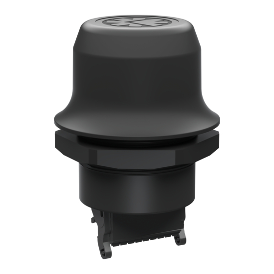
Page 4: Product Description
Interface configuration Interface 18-pin socket Interface RJ45 and 3-pin power socket Functionality Ethernet Ethernet and RS232/485 Ethernet and CAN Example: AWB2AA = Anybus Wireless Bolt with18-pin plug connector and Ethernet networking only. Anybus ® Wireless Bolt ™ Startup Guide SCM-1202-006/SP2139 EN 2.7... -
Page 5: Installation
50 cm between the devices should also be observed to avoid interference. The characteristics of the antenna should also be considered when choosing the placement and orientation of the unit. See the Anybus Wireless Bolt User Manual for more information. Anybus ®... -
Page 6: Mechanical Installation
Always hold the BOTTOM part of the unit when untightening the nut, not the top part (the cap). All measurements are in mm. Anybus ® Wireless Bolt ™ Startup Guide SCM-1202-006/SP2139 EN 2.7... - Page 7 Installation 7 (16) Connectors Note the location of the RESET button when the connector is attached to the Wireless Bolt. Pin 1 will be the pin closest to the button. 18–pin Connector Description Name Power 9–30 VDC Power Ground Digital input (9–30 VDC)
-
Page 8: Ethernet Cabling
8 (16) Ethernet Cabling To make an Ethernet connector cable for Anybus Wireless Bolt: Cut off one of the connectors on a standard Cat5e or Cat6 Ethernet cable. Strip off about 40 mm (1½ inch) of the cable jacket and untwist the orange, orange/white, green and green/white wires. -
Page 9: Reset Button
Recovery Mode If the web interface cannot be accessed, the unit can be reset by starting in Recovery Mode and reinstalling the firmware using Anybus Firmware Manager II, which can be downloaded from www.anybus.com/support. To enter Recovery Mode, press and hold RESET during startup. -
Page 10: Web Interface
Configuration 10 (16) Configuration Anybus Wireless Bolt is configured via a web interface. Parameters can be set individually or using pre-configured Easy Config modes. Advanced configuration can be carried out by issuing AT commands via the web interface or over a Telnet or RAW TCP connection to port 8080. - Page 11 Apply PROFINET optimization to both units. (any) Apply PROFINET optimization and restart. (any) Enable PROFIsafe mode. The Easy Config modes are also described in detail when selected in the web interface. Anybus ® Wireless Bolt ™ Startup Guide SCM-1202-006/SP2139 EN 2.7...
-
Page 12: Factory Restore
Channel Auto Bridge Mode Layer 3 IP forward Default Bluetooth Settings Operating Mode PANU (Client) Local Name [generated from MAC address] Connectable Discoverable Security Mode Just works Bluetooth LE Disabled Anybus ® Wireless Bolt ™ Startup Guide SCM-1202-006/SP2139 EN 2.7... -
Page 13: Configuration Examples
Adding More Devices Up to 6 additional clients can be added by repeating the procedure. Each new client will be assigned the next free IP address within the current subnet. Anybus ® Wireless Bolt ™ Startup Guide SCM-1202-006/SP2139 EN 2.7... -
Page 14: Technical Data
Technical Data 14 (16) Technical Data For complete technical specifications and regulatory compliance information please visit www.anybus.com/support. Hardware Specifications Order code AWB2000 AWB2001 Color Black White top and black base Wired interface type Ethernet Connector Included plug connector Antenna Internal dual-band 2.4 GHz and 5 GHz antenna... - Page 15 This page intentionally left blank...
-
Page 16: Emc Compliance (Ce)
Additional certification and compliance information EMC Compliance (CE) This product is in compliance with the Radio Equipment Directive 2014/53/EU through conformance with the following standards. The Declaration of Conformity can be found at www.anybus.com/support. Effective use of Safety frequency spectrum EN 300 328 V2.1.1... -
Page 17: Fcc Compliance Statement
Anybus ® Wireless Bolt Compliance Sheet 2 (2) ™ FCC Compliance Statement This equipment complies with FCC radiation exposure limits set forth for an uncontrolled environment. This equipment should be installed and operated with a minimum distance of 20 cm between the radiator and your body. - Page 18 According to the standards listed above, Anybus Wireless Bolt modules are certified with the following marking: According to the standards listed above, the Anybus Wireless Bolt modules shall be supplied by a CLASS 2 / SELV classified power supply. © 2018 HMS Industrial Networks AB...
-
Page 19: Ul Hazardous Locations (Haz.loc.)
Additional certification and compliance information UL Hazardous Locations (Haz.Loc.) Anybus Wireless Bolt is certified for use in hazardous locations in compliance with the following standards: • UL 121201 NONINCENDIVE ELECTRICAL EQUIPMENT FOR USE IN CLASS I AND II, DIVISION 2... - Page 20 Anybus ® Wireless Bolt Compliance Sheet 2 (2) ™ • Group D: Flammable gas, flammable liquid-produced vapor or combustible liquid-produced vapor mixed with air that may burn or explode, having either a maximum experimental safe gap (MESG) value greater than or equal to 0.75mm or minimum igniting current ratio (MIC ratio) greater than 0.80.
- Page 21 Anybus ® Wireless Bolt ™ Additional certification and compliance information ATEX The Anybus Wireless Bolt are certified for use in potentially explosive atmospheres in compliance with the following standards: • EN 60079-0: 2012 + A11:2013 • EN 60079-15: 2010 The certification number of the Anybus Wireless Bolt certified modules according to the ATEX directive 2014/34/EU is: •...
- Page 22 Anybus ® Wireless Bolt Compliance Sheet 2 (2) ™ Special Conditions of Use: • The equipment shall only be used in an area of at least pollution degree 2, as defined in IEC 60664-1. • The equipment shall be installed in an enclosure that provides a minimum ingress protection of IP 54 in accordance with EN 60079-15.
- Page 23 This page intentionally left blank...
- Page 24 last page © 2018 HMS Industrial Networks Box 4126 300 04 Halmstad, Sweden info@hms.se SCM-1202-006/SP2139 EN 2.7 / 2018-09-05 / 9494...
Need help?
Do you have a question about the Wireless Bolt and is the answer not in the manual?
Questions and answers