Anybus Wireless Bolt User Manual
Hide thumbs
Also See for Wireless Bolt:
- Startup manual (17 pages) ,
- Startup manual (25 pages) ,
- Reference manual (90 pages)
Table of Contents
Advertisement
Quick Links
Advertisement
Table of Contents

Related Manuals for Anybus Wireless Bolt


Summary of Contents for Anybus Wireless Bolt
- Page 1 Anybus ® Wireless Bolt ™ USER MANUAL SCM-1202-007-EN 2.5 ENGLISH...
- Page 2 These intellectual property rights may include patents and pending patent applications in the USA and other countries. Anybus ® is a registered trademark and Wireless Bolt ™ is a trademark of HMS Industrial Networks AB. All other trademarks mentioned in this document are the property of their respective holders.
-
Page 3: Table Of Contents
Adding wireless connectivity to a single Ethernet node............31 Accessing a PLC from a handheld device over WLAN ............32 B Wireless Technology Basics ..................33 C Technical Data........................ 34 Technical Specifications ....................34 Internal Antenna Characteristics ...................34 ® Anybus Wireless Bolt ™ User Manual SCM-1202-007-EN 2.5... - Page 4 This page intentionally left blank...
-
Page 5: Preface
Preface 3 (36) Preface About This Document This manual describes how to install and configure Anybus Wireless Bolt. For additional related documentation and file downloads, please visit the Anybus support website at www.anybus.com/support. Included Additional Files SCM-1202-061 UL Ord.Loc. compliance information SCM-1202-062 UL Haz.Loc. -
Page 6: Document Conventions
Caution This instruction must be followed to avoid a risk of personal injury. WARNING This instruction must be followed to avoid a risk of death or serious injury. ® Anybus Wireless Bolt ™ User Manual SCM-1202-007-EN 2.5... -
Page 7: Description
WLAN 5 GHz cannot be used at the same time as WLAN 2.4 GHz or Bluetooth. Bluetooth or WLAN? Use Bluetooth when... • ...the wireless link has an Anybus Wireless Bridge II or Anybus Wireless Bolt at both ends. • ...an interruption-free connection is more important than data throughput speed. •... -
Page 8: Model Name - Certification Identifier
Prefix AWB2 Anybus Wireless Bolt Interface configuration Interface 18-pin plug Functionality Ethernet Ethernet and RS232/485 Ethernet and CAN Example: AWB2AA = Anybus Wireless Bolt with18-pin connector and Ethernet networking only. ® Anybus Wireless Bolt ™ User Manual SCM-1202-007-EN 2.5... -
Page 9: Installation
For optimal reception, wireless devices require a zone between them clear of objects that could otherwise obstruct or reflect the signal. A minimum distance of 50 cm between the devices should also be observed to avoid interference. See also Wireless Technology Basics, p. ® Anybus Wireless Bolt ™ User Manual SCM-1202-007-EN 2.5... -
Page 10: Mechanical Installation
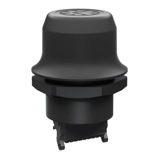
Installation 8 (36) Mechanical Installation Anybus Wireless Bolt is intended to be mounted on top of a machine or cabinet through an M50 (50.5 mm) hole using the included sealing ring and nut. Tightening torque: 5 Nm ±10 % Make sure that the sealing ring is correctly placed in the circular groove in the top part of the housing before tightening the nut. -
Page 11: Connector
Fig. 2 Connector The location of the RESET button can be used as a reference for the pin numbering when the connector is attached to the Wireless Bolt. Pin 1 will be the pin closest to the button. Description Name Power + (9–30 V) -
Page 12: Cabling
Installation 10 (36) Cabling To make an Ethernet connector cable for the Anybus Wireless Bolt: Fig. 3 Ethernet cable Cut off one of the connectors on a standard Cat5e or Cat6 Ethernet cable. Strip off about 40 mm (1½ inch) of the cable jacket and untwist the orange, orange/white, green and green/white wires. -
Page 13: Configuration
Telnet or RAW TCP connection to port 8080. The web interface is accessed by pointing a web browser to the IP address of the Wireless Bolt. The default address is 192.168.0.99. The computer accessing the web interface must be in the same IP subnet as the Wireless Bolt. -
Page 14: Web Interface
12 (36) Web Interface The web interface is accessed by pointing a web browser to the IP address of the Wireless Bolt. The default IP address is 192.168.0.99. The computer accessing the web interface must be in the same IP subnet as the Wireless Bolt. - Page 15 Mode 4 will listen for 120 seconds or until receiving a configuration. The IP address of a client may be changed by the configuration from the access point. Active browser sessions could therefore be lost. ® Anybus Wireless Bolt ™ User Manual SCM-1202-007-EN 2.5...
- Page 16 IP Address: 192.168.0.99, Start Address: 101 DHCP range = 192.168.0.101 – 192.168.0.107 IP Address: 192.168.0.103, Start Address: 101 DHCP range = 192.168.0.101 – 192.168.0.108 7 addresses are allocated but the address of the unit is skipped. ® Anybus Wireless Bolt ™ User Manual SCM-1202-007-EN 2.5...
- Page 17 Authentication details when using LEAP or PEAP (WPA2 Enterprise). Passphrase Channel Select a specific channel to use when scanning for networks. Which channels are available depend on the Channel Bands setting. Auto = all channels will be scanned (default). ® Anybus Wireless Bolt ™ User Manual SCM-1202-007-EN 2.5...
- Page 18 Use when multiple devices on both sides of an Ethernet network bridge must be able to communicate via WLAN (many-to-many). Only works between Anybus Wireless Bolt or Wireless Bridge II devices. Layer 2 cloned MAC only = Layer 2 data from only a single MAC address (specified below) will be bridged over WLAN (many-to-one).
- Page 19 The following settings are specific when Access Point mode is selected. Network (SSID) Enter an SSID (network name) for the Wireless Bolt. If this entry is left blank, the unit will generate an SSID which includes the last 6 characters of the MAC ID.
- Page 20 (not with third-party devices). PIN codes must consist of 4 to 6 digits. Just Works = Encrypted connection without PIN code. Paired Devices Lists the currently connected Bluetooth devices. ® Anybus Wireless Bolt ™ User Manual SCM-1202-007-EN 2.5...
- Page 21 Used when connecting manually to a NAP or PANU device. Connection Scheme Choose whether to select a Bluetooth device by MAC address or name when connecting manually. Name Name of the Bluetooth device to connect to. ® Anybus Wireless Bolt ™ User Manual SCM-1202-007-EN 2.5...
- Page 22 This mode must be used when connecting to an Android device over Bluetooth. The network must have an active DHCP server. List Nearby Devices Scans the network and lists discoverable Bluetooth devices. Pairing cannot be initiated in NAP mode. ® Anybus Wireless Bolt ™ User Manual SCM-1202-007-EN 2.5...
- Page 23 Click on Browse to select a firmware file, then click on Send to download it to the unit. Both progress bars will turn green when the firmware update has been completed. The unit will then reboot automatically. ® Anybus Wireless Bolt ™ User Manual SCM-1202-007-EN 2.5...
- Page 24 Enter or paste the commands into the text box, then click on Send. The result codes will be displayed below the text box. See the AT Commands Reference Guide for a complete list of supported AT commands. ® Anybus Wireless Bolt ™ User Manual SCM-1202-007-EN 2.5...
- Page 25 Restores all parameters in the web interface to the currently active values. Factory Reset Resets the unit to the factory default settings and reboots. Setting a secure password for the unit is strongly recommended. ® Anybus Wireless Bolt ™ User Manual SCM-1202-007-EN 2.5...
-
Page 26: Factory Restore
Default Bluetooth Settings Operating Mode PANU (Client) Local Name [generated from MAC address] Security Mode Just works Default System Settings Password [empty] Setting a secure password for the unit is strongly recommended. ® Anybus Wireless Bolt ™ User Manual SCM-1202-007-EN 2.5... -
Page 27: Reset Button
Recovery Mode If the web interface cannot be accessed, the unit can be reset by starting in Recovery Mode and reinstalling the firmware using Anybus Firmware Manager II, which can be downloaded from www.anybus.com/support. Firmware updates should normally be carried out through the web interface. - Page 28 This page intentionally left blank...
-
Page 29: A Configuration Examples
Appendix A: Configuration Examples 27 (36) Configuration Examples The following examples require that you have installed the Anybus Wireless Bolt and that you understand how to access and use the web interface. • All the examples start out from the factory default settings. -
Page 30: Profinet Networking Via Bluetooth (Easy Config)
PROFINET communication. Reset both Wireless Bolts to the factory default settings. Connect Wireless Bolt 1 to the IO device and Wireless Bolt 2 to the PLC. Set Wireless Bolt 1 to Easy Config Mode 4. This unit will now be discoverable and open for automatic configuration. -
Page 31: Ethernet/Ip Networking Via Bluetooth (Easy Config)
EtherNet/IP communication. Reset both Wireless Bolts to the factory default settings. Connect Wireless Bolt 1 to the IO device and Wireless Bolt 2 to the PLC. Set Wireless Bolt 1 to Easy Config Mode 4. This unit will now be discoverable and open for automatic configuration. -
Page 32: Connecting An Ethernet Network To An Existing Wlan
2 traffic, such as PROFINET. Configuration Reset the Wireless Bolt to the factory default settings. In Network Settings, configure the IP settings as required by the wireless network. If the network uses DHCP, select DHCP Relay Enabled. -
Page 33: Adding Wireless Connectivity To A Single Ethernet Node
Enter the MAC address of the PLC in the Cloned MAC Address field. 10. Click on Save and Reboot. The Wireless Bolt will now function as a WLAN interface for the PLC using the MAC address of its Ethernet interface. -
Page 34: Accessing A Plc From A Handheld Device Over Wlan
Accessing a PLC from a handheld device using WLAN This example describes how to use a Wireless Bolt to allow access to the web interface of a PLC or other device on a wired network from a tablet or smartphone that uses dynamic IP addressing (DHCP). -
Page 35: B Wireless Technology Basics
To reduce interference and phase cancelling, the range may also need to be limited by reducing the transmission power. For determining the optimal configuration and placement of wireless devices it is therefore recommended to use a wireless signal analysis tool. ® Anybus Wireless Bolt ™ User Manual SCM-1202-007-EN 2.5... -
Page 36: C Technical Data
Serial RS-232/485 + Ethernet CAN + Ethernet Wireless antenna Internal Maximum range 100 m (WLAN and Bluetooth) Communication See Anybus Wireless Bolt Datasheet Dimensions Height: 70 mm (95 mm incl. connector, 41 mm outside) Diameter: 70 mm Weight 81 g Operating temperature -40 to +65 °C... - Page 37 This page intentionally left blank...
- Page 38 last page © 2018 HMS Industrial Networks AB Box 4126 300 04 Halmstad, Sweden info@hms.se SCM-1202-007-EN 2.5.7278 / 2018-02-02...
Need help?
Do you have a question about the Wireless Bolt and is the answer not in the manual?
Questions and answers