Table of Contents
Advertisement
Advertisement
Table of Contents

Related Manuals for NAMCO Ridge Racer 2


Summary of Contents for NAMCO Ridge Racer 2
- Page 1 RIDGE RACER Operators Manual Part No 90500075...
- Page 2 No part of this publication may be reproduced by any mechanical, photographic or electronic process, or in the form of phonographic recording, nor may it be stored in a retrieval system, transmitted or otherwise copied for public or private use, without namco permission from Ltd.
-
Page 3: Table Of Contents
Contents Operators Manual ......................1 SPECIFICATIONS ....................5 MAJOR COMPONENTS ..................6 PRECAUTIONS ...................... 7 Cautions When Installing............... 7 Caution when Handling................7 When Transporting................7 INSTALLATION ...................... 8 Connecting the Seat Assemblies to the Cabinet........8 Adjusting the Level Adjusters.............. -
Page 4: Operators Manual
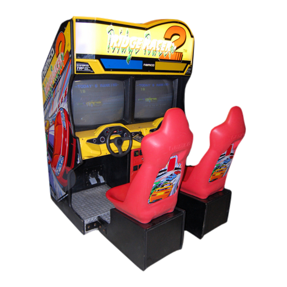
1. SPECIFICATIONS POWER SUPPLY :- 220/240volts AC MONITOR:- Hantarex 28" Polo Colour Monitor with auto degauss. DIMENSIONS :- When Assembled:- 1400(w) x 1770(d) x 1980(h) Cabinet:- 1400(w) x 920(d) x 1980(h) Seat Assy:- 470(w) x 940(d) x 1230(h) WEIGHT :- When Assembled:- 310kg Cabinet:-... -
Page 5: Major Components
2. MAJOR COMPONENTS Page... -
Page 6: Precautions
3. PRECAUTIONS 3-1 Cautions When Installing. This game is designed for indoor use only. The game must not be installed outdoors or under the following conditions:- In areas directly exposed to sunlight, high humidity, direct water contact, dust, high heat or extreme cold. In locations that would present an obstacle in the case of an emergency, i.e.. -
Page 7: Installation
4. INSTALLATION Remove from the cash box the four joint plates, 24off M10x30 hex head bolts, 24off M10 flat washers and 24off M10 spring washers. 4-1 Connecting the Seat Assemblies to the Cabinet 1. Place the cabinet in the installation position. 2. -
Page 8: Test Mode
5-3 Test Mode Open the coin door, set the test switch to "ON". The "Menu Screen" appears on the monitor display. Select the item to be tested by turning the steering wheel right or left. The colour of the item you select changes. Step on the accelerator pedal to display the menu of the selected item. -
Page 9: Setting The Game Fee And So On (On The Coin Options Screen)
5-3-1 Setting the Game Fee and So On (On the Coin Options Screen) Select 1 “COIN OPTIONS” on the COIN OPTIONS Menu Screen to set the game fee Turn the steering wheel to select GAME COST the item to be changed, then 2 COINS 1 CREDIT step on the accelerator pedal. -
Page 10: Changing The Game Settings (On The Game Options Screen)
5-3-2 Changing the Game Settings (on the Game Options Screen) Select 2 “GAME OPTIONS” to GAME OPTIONS change the game options. (DEFAULT GREEN) G A M E D I F F I C U L T Y T I M E E X T E N D Turn the steering wheel to select N O V I C E... -
Page 11: Switch Test
5-3-3 Switch Test Select 3 “SWITCH TEST” to display the following screen. SWITCH TEST DIP SW2 1 2 3 4 5 6 7 8 (a) Option switch (SW2 on the CPU) SW3 1 2 3 4 5 6 7 8 (b) Option switch (SW3 on the CPU) STEERING *0000... -
Page 12: Sound Test (Adjusting The Sound Volume)
5-3-4 Sound Test (Adjusting the Sound Volume) Select “SOUND TEST” on the menu screen to adjust the sound volume. The following screen appears. SOUND TEST VOLUME(L) (a) Sound volume for left speakers VOLUME(R) (b) Sound volume for right speakers STEREO CHECK (c) Stereo checking function SONG EXIT=STEP ON THE BRAKE... -
Page 13: Adjusting The Game After Replacing Parts (Initializing The Game)
5-4 Adjusting the Game After Replacing Parts (Initializing the Game) Be sure to adjust the game with the following instructions below after replacing any part. Otherwise, the game will not function correctly. Ensure that the accelerator and brake pedals are released and the steering is in the centre. -
Page 14: Connecting Multiple Game Links
5-5 CONNECTING MULTIPLE GAME LINKS When installing more than one Ridge Racer 2™ game, the units must be linked using screened audio cable (One lead is supplied with each machine) Ensure that all leg levellers on the game cabinets and seats have all been lowered, and that all castors are clear of the floor. -
Page 15: How To Play
6. HOW TO PLAY • Players can race by themselves against the computer or head to head on the same track. With four machines linked, up to 8 players can race on the same track. • Four difficulties are provided. NOVICE, INTERMEDIATE, ADVANCED and T.T.(Time Trials), with up/down gear shift or fully automatic transmission. -
Page 16: Maintenance
7. MAINTENANCE 7-1 Replacing Fluorescent Lamps Remove the ten M5x16 button head screws, and remove the top flash (see fig. below). taking care to unplug the 2 Leading Driver Lamp plugs. Replace the fluorescent lamp and/or starter. 7-2 Replacing the Leading Driver Lamps Remove the ten M5x16 button head screws, and remove the top flash (see fig. -
Page 17: Removing The Game Printed Circuit Board (Pcb)
7-3 Removing the Game Printed Circuit Board (PCB) Remove the back door, Remove two assembling bolts (M6 x 30), then pull out the power control panel about 25cm. (Note: if you pull it out too much, it will be detached). Disconnect two connectors on the EMI board, then... -
Page 18: Removing The Shield Case
7-4 Removing the Shield Case Perform Steps (1) and (2) described in Section 7-3. Disconnect the connector of the AC Fan. Remove two cup screw (M5 x 14) then take out the shield case. 7-5 Removing the Power Control Panel Perform steps 1, 2, 5 and 6 described in Section 7-3. -
Page 19: Replacing The Control
7-8 Steering Assy 7-8-1 Replacing the control Remove 4off M5x20 button head screws and pull forward the play panel assy to gain access to the steering assy. Loosen the grub screw on the gear wheel and remove the gear wheel. Replace the control potentiometer. -
Page 20: Parts
88300079 Play Panel Instruction Decal 40000043 75mm Castor 59000005 Seat - Back Decal 40000035 Seat - Ridge Racer Decal 40000042 Seat - Namco Decal 40000036 Top Flash System 22 (Left) Decal 40000039 Top Flash System 22 (Right) Decal 40000040 Page... -
Page 21: Schematic
9. SCHEMATIC Page... - Page 22 Page...
Need help?
Do you have a question about the Ridge Racer 2 and is the answer not in the manual?
Questions and answers