
Subscribe to Our Youtube Channel
Related Manuals for NAMCO Alpine Racer


Summary of Contents for NAMCO Alpine Racer
- Page 1 52" Operators Manual T IS THE RESPONSIBILITY OF THE OPERATOR TO MAINTAIN CUSTOMER SAFETY AT ALL TIMES AND IT IS IMPERATIVE THAT THE DETAILS SET OUT IN THIS MANUAL ARE FOLLOWED PRECISELY Part No. 90500085...
- Page 2 NAMCO EUROPE LIMITED While the information contained in this manual is given in good faith and was accurate at the time of publication, NAMCO EUROPE LTD. reserve the right to make changes and alterations without notice. This machine has been manufactured in accordance with European Community directives (1st.
- Page 3 Warnings for Disassembly, Installation, Routine Maintenance, and Troubleshooting. DANGER: Namco Ltd. bears absolutely no responsibility for accidents or injuries resulting from unauthorized changes to this machine. DANGER: Ensure that the machine has been turned OFF before making adjustments or carrying out maintenance.
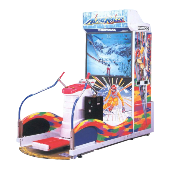
- Page 4 1. SPECIFICATIONS POWER SUPPLY :- 230volts AC MONITOR :- Thomson 52" Projector Monitor (RP52) COIN ACCEPTOR Mars CashFlow - 1 Channel DIMENSIONS :- Assembled 1265(w) x 2245(d) x 2320(h) Monitor Cabinet 1250(w) x 645(d) x 1940(h) Ski Assembly 1265(w) x 1600(d) x 1220(h) Header 1145(w) x 350(d) x 380(h) WEIGHT :-...
- Page 5 2. PRECAUTIONS Be sure to read this section carefully. 2-1 Notes on Operation ( Requirements) NOTE: Only operate this machine after checking that it has been installed correctly and in accordance with the Installation and Commisioning Manual. NOTE: Parts of this machine move during game play, so there are places where the distance between the stationary section and moveable section changes.
- Page 6 2-3 Cautions When Transporting. Do not subject the game to physical shock when transporting or moving it. Always return the levellers to the UP position before moving the machine, even for short distances. The monitor cabinet, ski assy and header assy must be separated before shipping.
- Page 7 2-4 Cautions When Installing. This machine is designed for indoor use only. Do Not install the machine in the following places If this machine is installed next to walls or other machines, ensure that there is plenty of space between them. Page 9...
- Page 8 NOTE: So that customers are not injured by the movement of the Ski Tray, ensure that there is at least 300mm separation between other machines or walls. If two Alpine Racer machines are next to each other the space between them must be at least 600mm.
- Page 9 3. HOW TO PLAY This game is based on Alpine ski racing. The player stands on the steps and moves them left or right to control the skier. By using the inner edge when moving the steps, the skier slows down and turns quickly.
- Page 10 4. MAJOR COMPONENTS Page 12...
- Page 11 5. INSTALLATION WARNING If the location site of this machine has a polished floor it is recommended that rubber pads are fitted under the level adjusters to prevent the machine sliding on the floor. 5-1 Fitting the Header Assembly The Header Assembly has a forward centre of gravity, so it is important that at least two people are used to fit or remove the Header Assembly.
- Page 12 5-2 Connecting the Ski Assy to the Monitor Cabinet. Connect the connectors between the Ski Assembly and Monitor Cabinet. Push the Ski Assembly fully up to the monitor cabinet, taking care not to trap any wires. Fit, finger tight, a joint bracket to each side using 4off Hex Head Set Screws (M10x25), Spring and Flat Washers on each bracket.
- Page 13 NOTE:- When the machine is fully assembled and in its final position, lower the 10 level adjusters, (4 on the monitor cabinet and 6 on the ski assy), with a spanner so that all castors are raised from the floor by approximately 5mm, and the machine is level.
- Page 14 6. ADJUSTMENTS 6-1 Turning on the Power After the machine has been installed, turn ON the power. The power switch is located on the rear of the monitor cabinet. 6-2 Adjustment Switches The Adjustment switches are located inside the coin door. Service Switch.
- Page 15 6-3 Test Mode Open the coin door and slide the test switch "ON". The menu screen will be displayed on the monitor. Select the test required by pressing the 'Left or Right Selection' push button. The selected test will 'blink'. Enter the selected test by pressing the 'Decision' push button.
- Page 16 6-3-1 Coin Options Select item (1) "COIN OPTIONS" on the menu screen to set the game cost and COIN OPTIONS related settings. [ DEFAULT IN GREEN ] Press 'Select L/R' to GAME COST select the required 1 COIN 1 CREDIT ------------------------ (a) item.
- Page 17 6-3-2 Game Options Select item (2) "GAME OPTIONS" on the menu screen to set the game options and related settings. Press 'Select L/R' to select the required item. Press the 'Decision' button to adjust the settings. Standard settings are displayed in green. Select "EXIT"...
- Page 18 6-3-3 I/O Test Select item (3) "I/O Test" on the menu screen to test the switches, motor and step adjust. Press 'Select L/R' to select the required item, then press the 'Decision' button to enter the test. Select "EXIT" and press the 'Decision' button to return to the menu screen. I/O TEST DIP 4 12345678...
- Page 19 6-3-3-1 Switch Test Select Switch Test from the 'I/O Test' menu. The following screen will appear on the monitor. Note:- On entering Switch Test the Skis will be unlocked. Ensure that the Skis are returned to the locked condition at the end of the test by entering Motor Test (See 6-3-3-2) SWITCH TEST...
- Page 20 6-3-3-2 Motor Test Select Motor Test from the 'I/O Test' menu. The following screen will appear on the monitor. MOTOR TEST NOW MOTOR STATE : LOCK ....(a) GO MOTOR : FREE ....(b) EXIT L/R SELECT BUTTON : CHOOSE DECISION BUTTON : EXIT Displays the current condition of the Skis.
- Page 21 6-3-4 Sound Test Select item (4) "Sound Test" on the menu screen to test the sound and speakers. The following screen will appear on the monitor. SOUND TEST VOLUME LEFT SP. ------------------- (a) RIGHT SP. ------------------- (b) REQUEST SONG No. ------------------- (c) EXIT L/R SELECT BUTTON : CHOOSE...
- Page 22 6-3-5 Monitor Test Select item (5) “Monitor Test” on the menu screen to set up and adjust the monitor. On entering monitor test, the screen will display one of the following test patterns. GRADATION PATTERN CROSSHATCH GREEN CROSSHATCH WHITE WHITE WINDOW WHITE WINDOW WHITE WINDOW INTERLACE PATTERN...
- Page 23 Item Description (a) Play Total number of games played at each difficulty level for each course. (b) Goal Total number of games completed at each difficulty level for each course. (c) Ext0 Number of games finishing at 1st extended time gate at each difficulty level in race game.
- Page 24 6-4 Initialization After Replacing Parts Initialization must be performed after replacing the game PC board, Rom or Step Controls. If initialization is not performed, the game will not function correctly. During initialization, ensure that the step edges are level. 6-4-1 Adjustment Method (a) When the power is turned ON the step-lock motor is automatically checked.
- Page 25 6-4-2 Adjustment Method (b) Slide the test switch ON. Turn the power OFF and then back ON again. Select "I/'O TEST" and press the decision button (View Change). Select "STEP ADJUST" and press the decision button. The controls are now initialized.
- Page 26 If the first lock is completed within fifteen seconds, but the steps cannot be MOTOR ERROR 2 released, Motor Error 2 screen is OPERATION STOP!! displayed until the fault is rectified. If after the steps have been freed, they do not re-lock, as an emergency measure, Motor Error 3 screen is displayed.
- Page 27 7. MAINTENANCE DANGER: In order to prevent injury or electric shock to service personnel, ensure that the MAIN POWER IS OFF before attempting any maintenance. DANGER: Before performing any work not described in this manual, be sure to contact your distributor to receive instructions or answers to questions. 7-1 Care of the Projector Monitor The projection tube lenses have been manufactured from plastic material.
- Page 28 7-2 Replacing the Fluorescent Tube Remove the ten socket button head screws (M5x12), and remove the side vac- forms (five screws on each vac-form) Remove the two countersunk screws (M5x12) from the bottom of the acrylic. Remove the two socket button head screws (M4x25), and remove the header acrylic retaining bracket.
- Page 29 7-3 Replacing Push Button Switches and Lamps Remove six security screws (M5x20) and two security screws (M5x12), and lift off the top cover taking care not to strain the wiring. Disconnect the connector. Separate the switch/lamp holder from the button by pulling it directly away from the button.
- Page 30 7-4 Replacing the Step Limit Switches WARNING: Ensure that the machine is disconnected from the main power supply before commencing work. Remove the top cover. (See Section 7-3) Remove four security screws (M5x12) securing each side vac-form to the mast assembly and remove both side vac-forms and front vac-form as one assembly.
- Page 31 Remove two pozi head screws (M3x16) and replace the limit switch ensuring the wires are replaced on the correct terminals. Reassemble in reverse order. 7-5 Replacing the L/R Turn Control Pot WARNING: Ensure that the machine is disconnected from the main power supply before commencing work.
- Page 32 Disconnect the connector, slacken the pot retaining grub screw (M4x8) and remove the control pot and bracket. Replace the control pot taking care to ensure that the wires are replaced to the correct terminals. Reassemble in reverse order. Re-initialize game. (See 7-7 "Adjustments When Replacing Parts") NOTE: When refitting the control pot ensure that the pot locating tab engages in the hole in the mounting bracket and that the grub screw (M4x8)
- Page 33 7-6 Replacing the Tilt Control Pot Remove the front vac-form. (See Section 7-3) Remove four security head screws (M5x12) and remove the Ski Step front vac- form. Disconnect the connector, slacken the pot retaining grub screw (M4x8) and remove the control pot and bracket. Replace the control pot taking care to ensure that the wires are replaced to the correct terminals.
- Page 34 7-7 Removing the Step Rubber Remove three security screws (M5x12) and retaining bracket from the outside edge of the step rubber, Lift the rubber edge and remove the three inner security screws (M5x12) and retaining bracket. Tilt the step assembly and remove three security screws (M5x12). Remove the step rubber.
- Page 35 7-8 Step-Lock Maintenance 7-8-1 Releasing the Step-Lock Turn the power switch ON Press the service switch, and start the game. When the game starts, the restriction plate (see diag.) moves to the released position. When the steps are released, turn the power OFF. To re-lock the steps turn the power ON and the steps will re-lock in the power up motor check.
- Page 36 7-8-3 Inspecting the Pillow Unit WARNING Make sure that the power is turned OFF. If work is to be carried out with the covers removed, take care not to trap hands or fingers in the mechanism. When greasing the step-lock, inspect the pillow assembly for any problems. Release the step-lock and swing the steps to the left and right, and check the pillow units for any wear.
- Page 37 8. TROUBLE SHOOTING • Ensure that the power is turned OFF before making adjustments or replacing parts. • If none of the items below correspond to your problem, or if the problem is not corrected by the treatment described below, contact your dealer for further advice.
- Page 38 8-3 Header Assembly Symptom Cause Treatment Ref. Page The fluorescent lamp does not Is the connector loose or Connect the connector pg44 come on. disconnected. securely. schematic Is the fluorescent tube or Replace tube or starter. pg25 7-2 starter burned out. 8-4 Mast Assembly Symptom Cause...
- Page 39 9. PARTS WARNING: Many of the parts used in this machine, including metal work, have been manufactured to special specifications. To ensure continuing safety and correct operation, replace only with genuine NAMCO parts. ITEM DESCRIPTION PART No. HEADER ACRYLIC 30000222...
- Page 40 ITEM DESCRIPTION PART No THOMSON 52" PROJECTION MONITOR 84000030 PROJECTOR CABINET SIDE DECAL - LHS/RHS 40000284 ALPINE RACER PCB ASSY - SYSTEM 22 XAR-PCB SMPSU 5v/30A - 12v/5A 83000001 ELKAY BLOCK 5 WAY 66000014 FUSE 1¼" 2A QUICK-BLO 63500504 FUSE 1¼" 3A SLO-BLO...
- Page 41 Page 43...
- Page 42 ITEM DESCRIPTION PART No MAIN BASE METALWORK 45000585 MAIN BASE EXTENSION ARM - RHS 45000586 MAIN BASE EXTENSION ARM - LHS 45000587 MAIN BASE EXTENSION ARM VAC-FORM - LHS 45000588 MAIN BASE EXTENSION ARM VAC-FORM - RHS 45000589 SNOW FIELD VAC-FORM - LHS 45000590 SNOW FIELD VAC-FORM - RHS 45000591...
- Page 43 Page 45...
- Page 44 ITEM DESCRIPTION PART No. ITEM DESCRIPTION PART No. MAIN MAST METAL WORK 45000643 JOINT AL-050-12 45000667 PLAY INSTRUCTION ACRYLIC 30000220 MAST FRONT COVER VAC-FORM 45000644 CONTROL PANEL DECAL 40000271 MAST SIDE VAC-FORM - LHS 45000645 MAST SIDE VAC-FORM - RHS 45000646 FRONT CLOSING BRACKET COVER PLATE 45000662...
- Page 46 ITEM DESCRIPTION PART No STEP ASSY MAIN METAL STRUCTURE 45000618 STEP TRAY ASSY 45000619 STEP VAC-FORM - FRONT 45000620 STEP VAC-FORM - REAR 45000621 STEP RUBBER 45000622 ROSTA SPRING BRACKET - FRONT 38x60 45000623 ROSTA SPRING BRACKET - REAR 38x60 45000624 ROSTA SPRING SWING BRACKET 38x60 45000625...
- Page 47 10. SCHEMATICS Page 49...
- Page 48 Page 50...
- Page 49 Page 51...
- Page 50 Page 52...
Need help?
Do you have a question about the Alpine Racer and is the answer not in the manual?
Questions and answers