Hitachi RASC-4HNPE Service Manual
Centrifugal vrf series rasc-hnpe
Hide thumbs
Also See for RASC-4HNPE:
- Instruction manual (232 pages) ,
- Installation and operation manual (60 pages)

Related Manuals for Hitachi RASC-4HNPE


Summary of Contents for Hitachi RASC-4HNPE
- Page 1 CENTRIFUGAL VRF SERIES RASC-HNPE Service Manual RASC-4HNPE RASC-5HNPE RASC-6HNPE RASC-8HNPE RASC-10HNPE...
- Page 3 Contents C o n t e n t s General information Unit installation Piping work and refrigerant charge Electrical and control settings Control system Optional functions Commissioning Electrical checks of the main parts Servicing Troubleshooting Maintenance notes SMGB0091 rev.2 - 11/2015...
-
Page 5: Table Of Contents
General Index General Index General information ....................1 General information ..........................2 1.1.1 General notes ..............................2 1.1.2 Introduction ..............................2 1.1.3 Environment-friendly units ..........................2 Applied symbols ............................3 Product guide ............................4 1.3.1 Classification of RASC unit models ......................... 4 1.3.2 Classification of indoor unit models ......................... 4 1.3.3 ... - Page 6 General Index 3.3 Refrigerant piping range ........................38 3.3.1 Refrigerant piping length ..........................38 3.3.2 Piping system (Header branch installation) ....................38 3.3.3 Piping system (Line branch installation) ......................41 3.3.4 Combinations of piping size and piping length ....................42 3.3.5 Refrigerant piping size and multikit/distributor selection ................43 3.3.6 Considerations when installing distributors ....................
- Page 7 General Index 4.7 H-LINK II system ........................... 70 4.7.1 Application ..............................70 4.7.2 Features ................................ 70 4.7.3 Specifications ..............................70 4.7.4 DIP Switch setting for multiple H-LINK system ..................... 71 4.7.5 Examples of the system of connection between H-LINK and H-LINK II units ..........72 4.7.6 Examples of H-LINK II system ........................73 Electrical wiring diagrams........................75 4.8.1 RASC-(4-6)HNPE (3N~ 400V 50Hz) ......................75 4.8.2 RASC-(8/10)HNPE (3N~ 400V 50Hz) ......................76 Control system ......................
- Page 8 General Index Test run procedure using the wireless remote control switch (PC-LH3A) ........... 125 7.5 Test run procedure from the RASC unit ....................127 Check list on test run ........................... 128 Electrical checks of the main parts ..............129 Inverter ..............................130 8.1.1 Specifications of inverter ..........................130 8.1.2 Inverter time chart ............................
- Page 9 General Index 9.3.8 Removing air outlet panel ..........................150 9.3.9 Removing fan motor ............................ 151 9.3.10 Replacement of the compressor ....................... 159 9.3.11 Replacement of the pressure protection devices ..................162 9.3.12 Replacement of the reversing valve coil ....................163 9.3.13 Replacement of the expansion valve coil ....................164 9.3.14 Replacement of the solenoid valve coil (SVA and SVC) ................164 9.3.15 Replacement of the reversing valve ......................165 9.3.16 Replacement of the expansion valve and solenoid valves (SVA, SVC) ............ 166 9.3.17 Removal of the electrical components (for 4-6 HP) ................... 167 9.3.18 ...
- Page 10 General Index 11.2 Maintenance work ..........................287 11.3 Service and maintenance record......................288 11.4 Service and maintenance record using the 7-segment display ............289 11.5 Service and maintenance record by remote control switch ..............291 11.6 Pump-down method for replacing the compressor................292 VIII SMGB0091 rev.2 - 11/2015...
-
Page 11: General Information
1 General information G e n e r a l i n f o r m a t i o n Index General information ..........................2 1.1.1 General notes ..............................2 1.1.2 Introduction ..............................2 1.1.3 Environment-friendly units ..........................2 Applied symbols ............................ -
Page 12: General Information
This document may therefore have been subject to amendments during the life of the product. HITACHI makes every effort to offer correct, up-to-date documentation. Despite this, printing errors cannot be controlled by HITACHI and are not its responsibility. -
Page 13: Applied Symbols
1 General information Applied symbols 1.2 Applied symbols During normal air conditioning system design work or unit installation, greater attention must be paid in certain situations requiring particular care in order to avoid damage to the unit, the installation or the building or property. Situations that pose a risk to the safety of those in the surrounding area or to the unit itself are clearly indicated in this manual. A series of special symbols is used to clearly identify these situations. Pay close attention to these symbols and to the messages following them, as your safety and that of others depends on it. D A N G E R • The text following this symbol contains information and instructions relating directly to your safety. •... -
Page 14: Product Guide
All references of the “Built-in-horizontal” units contained into this document, have been abbreviated as “RASC” unit. • HITACHI has a range of remote control systems that can be used with the UTOPIA RASC units. Please, refer to the Controls Technical Catalogue. -
Page 15: Product Guide: Indoor Units
1 General information Product guide 1.3.4 Product guide: Indoor units N O T E • The indoor unit models and codes are the last updated at time of publication; other previous models and coming developments could be available for combination with RASC series. •... - Page 16 1 General information Product guide 2-way cassette Ceiling type Ceiling type (high efficiency) Unit Code Unit Code Unit Code RCD-1.0FSN2 60278029 RCD-1.5FSN2 60278030 RPC-1.5FSN3 60278164 RCD-2.0FSN2 60278031 RPC-2.0FSN3 60278165 RCD-2.5FSN2 60278032 RPC-2.5FSN3 60278166 RCD-3.0FSN2 60278033 RPC-3.0FSN3E 7E443005 RPC-3.0FSN3 60278167 RCD-4.0FSN2 60278034 RPC-4.0FSN3E 7E443007 RPC-4.0FSN3 60278168 RCD-5.0FSN2 60278035...
- Page 17 1 General information Product guide RPIM Indoor ducted unit Unit Code Unit Code Unit Code Unit Code RPIM-0.8FSN4E 7E430013 RPI-0.8FSN4E 7E424013 RPIM-0.8FSN4E-DU 7E431013 RPIM-1.0FSN4E 7E430014 RPI-1.0FSN4E 7E424014 RPIM-1.0FSN4E-DU 7E431014 RPIM-1.5FSN4E 7E430015 RPI-1.5FSN4E 7E424015 RPIM-1.5FSN4E-DU 7E431015 RPI-2.0FSN4E 7E424016 RPI-2.5FSN4E 7E424017 RPI-3.0FSN4E 7E424018 RPI-4.0FSN4E 7E424020...
-
Page 18: List Of Accessories
1 General information Product guide 1.3.5 List of accessories Remote control systems Individual remote controls Name Description Code Figure PC-ARF Remote control with timer 70510001 PC-ART Remote control with timer 70510000 PC-ARH Simplified remote control 60291486 PC-LH3A 60291056 Wireless remote control PC-LH3B 60291770 Receiver kit for combination with wireless remote control switch Name Description Code... - Page 19 1 General information Product guide Centralised remote controls Name Description Code Figure PSC-A64GT Touch screen central station 60291730 PSC-A32MN Touch screen central station mini 60291966 PSC-A64S Centralised remote control 60291479 PSC-A16RS Centralised ON/OFF control 60291484 Building air conditioning controls Name Description Code Figure CSNET WEB Centralised control system which runs CSNET WEB software ...
- Page 20 1 General information Product guide Gateways for building management systems (BMS) Name Description Code Figure Integration with installation with intelligent control (Building HC-A8MB Management System) Gateway Interface to MODBUS 7E513204 systems (Max. 8 indoor units). Integration with installation with intelligent control (Building HC-A64MB Management System) Gateway Interface to MODBUS 7E513205 systems (Max. 64 indoor units). Integration with installations with intelligent control (BMS). HC-A16KNX 7E513300 Gateway Interface to KNX systems. Integration with installations with intelligent control (BMS) KNX001 7E512100 through CSNET WEB. Gateway Interface to KNX systems. Integration with installation with intelligent control (Building Management System) Gateway Interface to LONWORKS HARC-BX E (A) 60290874 systems. (H-LINK I communication) (Max. 64 units with 8 parameters) Integration with installation with intelligent control (Building Management System) Gateway Interface to LONWORKS ...
-
Page 21: Smgb0091 Rev.2
Net configuration kit for HC-A(8/64)MB and HC-A64NET 7E512306 N O T E In addition to all the aforementioned HITACHI controls, there are some non-HITACHI devices for combination with HITACHI Air Conditioning systems. Please refer to the Technical Catalogue of Controllers for Package for more information. ... - Page 22 1 General information Product guide Multikits Name Description Code Figure TE-03N1 70527012 TE-04N1 70527013 TE-56N1 70527014 TE-08N 70800003 TE-10N 70800004 TW-52AN 60291816 Branch pipe UTOPIA (pipe kit) TW-102AN 60291817 TG-53AN 60291818 TG-103AN 60291819 TRE-46N1 70527015 Distributor UTOPIA TRE-812N1 70527016 QE-812N1 Distributor UTOPIA 70527017 E-102SN3 70524101 Branch pipe (multikit) E-162SN3 70524102 SMGB0091 rev.2 - 11/2015...
-
Page 23: Unit Installation
2 Unit installation U n i t i n s t a l l a t i o n Index Initial check............................14 Transportation ............................15 2.2.1 Hanging method ............................15 2.2.2 Handling unit (centre of gravity) ........................16 Factory-supplied components ....................... 16 Installation space........................... -
Page 24: Initial Check
2 Unit installation Initial check 2.1 Initial check C A U T I O N • Install the RASC unit in a restricted area not accessible by the general public. • Do not install the unit outdoors (Water proof class: IPX0).Only indoor installation is allowed, and air for both suction and discharge must come from outside the building. -
Page 25: Transportation
2 Unit installation Transportation 2.2 Transportation D A N G E R Do not put any foreign material into the RASC unit and check to ensure that none exists in the RASC unit before the installation and test run. Otherwise, a fire or failure will occur. 2.2.1 Hanging method When hanging the unit, ensure the balance of the unit, check safety and lift it up smoothly. -
Page 26: Handling Unit (Centre Of Gravity)
For attaching in the refrigerant label. Installation and operation manual Installation and operation unit instructions. Product fiche (Only for RASC-4HNPE) Energy label (Only for RASC-4HNPE) For brazing to the field supplied gas line, and connecting to the gas valve. Gas pipe accessory (Only for RASC-(8/10)HNPE) SMGB0091 rev.2 - 11/2015... -
Page 27: Installation Space
2 Unit installation Installation space 2.4 Installation space Units in mm. RASC-(4-10)HNPE N O T E (*): Recommended servicing space for fan unit in those cases where it is not possible to access from the unit’s side. In these cases, a “removable servicing duct”... -
Page 28: Interchangeability Of Air Inlet And Outlet Panels
2 Unit installation Interchangeability of air inlet and outlet panels 2.5 Interchangeability of air inlet and outlet panels RASC units can be used in different air inlet/outlet configurations, just by switching the air inlet panel with the cycle service cover or the air outlet panel with the fan service cover. With respect to the air outlet panel, the change of position entails the rotation of the fan motor as well. - Page 29 2 Unit installation Interchangeability of air inlet and outlet panels 2 Remove the cycle service cover: a. Remove the 3 fixing screws. Screws b. Slide the service cover upward. Then, pull backwards and remove it using the handle. 3 Finally, exchange both covers and tighten them with their respective screws.
- Page 30 2 Unit installation Interchangeability of air inlet and outlet panels 2 Remove the air outlet panel as described on chapter “9. Servicing” “9.3.8 Removing air outlet panel”. 3 Unscrew the 4 fixing nuts of the fan unit feet: From the fan service cover, unscrew the 2 nuts of one of the fan unit side feet.
- Page 31 2 Unit installation Interchangeability of air inlet and outlet panels 5 Remove the wiring from the clamps before Clamps turning the fan to the optional position. Clamps 6 Lift the fan unit up slightly, turn it to the optional position, place both fan unit feet into their corresponding bolts for this optional position and fix the 4 screws to the fan unit feet.
- Page 32 8 Once the fan is placed to the optional position, proceed to the assembly of the fan duct accessory (provided separately). HITACHI accessory code: Š 7E590904 (for 4-6 HP) Š 7E590905 (for 8/10 HP) 9 The fan duct accessory consists of 4 plates: 2 long plates (for horizontal position) and 2 short plates (for vertical position).
- Page 33 2 Unit installation Interchangeability of air inlet and outlet panels 11 Finally, install all the covers again screwing them. SMGB0091 rev.2 - 11/2015...
-
Page 34: Installation Place Provision
2 Unit installation Installation place provision 2.6 Installation place provision Floor mounted 1 Foundation could be on flat and is recommended be 100‑300mm higher than floor level. 2 Install a drainage around foundation for smooth drain. 3 When installing the unit fix it by anchor bolts of M10. 4 Use vibration-proof rubber (approx. -
Page 35: Fan Performance Curves
In case of using suction and/or discharge air ducts, check the fan performance curve and decide which ducts are suitable according to the external static pressure (Pa) / air flow volume (m /min.). RASC-4HNPE RASC-5HNPE Air flow (m³/min) Air flow (m³/min) - Page 36 2 Unit installation Fan performance curves RASC-10HNPE N O T E • When designing a duct, check to ensure that the Air volume is within working range as indicated in the fan performance curves. • If the Air volume is set outside working range, water carry- over (drop in the ceiling or into the room), noise increase, damage to fan motor (high temperature) or insufficient Cooling/Heating capacity phenomena can occur.
-
Page 37: Duct Connection
2 Unit installation Duct connection 2.8 Duct connection Install the duct with down slope to prevent entry of rain water. Also, provide insulation for duct and connection in order to prevent dew formation. 1/50 or more SMGB0091 rev.2 - 11/2015... -
Page 39: Piping Work And Refrigerant Charge
3 Piping work and refrigerant charge P i p i n g w o r k a n d r e f r i g e r a n t c h a r g e Index Piping work connection considerations ....................30 3.1.1 Copper pipes and sizes .......................... -
Page 40: Piping Work Connection Considerations
3 Piping work and refrigerant charge Piping work connection considerations 3.1 Piping work connection considerations 3.1.1 Copper pipes and sizes 1 Prepare locally-supplied copper pipes. 2 Select the correct pipe size and material. Use the table below to select the required piping. Nominal Diameter Thickness Copper Type... -
Page 41: Pipe Connection
3 Piping work and refrigerant charge Piping work connection considerations 3.1.2 Pipe connection Fix the connecting pipe as shown in the figure below. Use the insulation attached to the indoor unit. Use the flare Insulate this part Fix this part with the nut of the with the insulation bracket supplied or... -
Page 42: Three Principles On Refrigerant Piping Work
3 Piping work and refrigerant charge Piping work connection considerations 3.1.4 Three principles on refrigerant piping work In case of using refrigerant R410A in the refrigeration cycle, the refrigeration oil should be of a synthetic type one. In order to avoid oxidation, pay much careful attention to basic piping work control to avoid infiltration of moisture or dust during the refrigerant piping work. -
Page 43: Suspension Of Refrigerant Piping
3 Piping work and refrigerant charge Piping work connection considerations 3.1.5 Suspension of refrigerant piping Suspend the refrigerant piping at certain points and prevent the refrigerant piping from touching the weak part of the building such as wall, ceiling, etc… (If touched, abnormal sound may occur due to the vibration of the piping. -
Page 44: Piping Connection For Rasc Unit
3 Piping work and refrigerant charge Piping connection for RASC unit A basic brazing method is shown below. Pre-heat the outer tube for better flowing of the filler metal Heat inner side tube evenly Rubber plug ... - Page 45 3 Piping work and refrigerant charge Piping connection for RASC unit 5 After connecting the refrigerant piping, seal the open space between knockout hole and refrigerant pipes by using insulation material. Nº Description Insulation Material Unit Insulation Material Side Field Supplied ...
- Page 46 3 Piping work and refrigerant charge Piping connection for RASC unit Spindle type Nº Description Remarks Allen wrench Hex 4 mm Refrigerant piping Field supplied Flare nut Refrigerant pressure To RASC unit Seat Surface Fully closed position ...
- Page 47 3 Piping work and refrigerant charge Piping connection for RASC unit Gas pipe accessory (Only for RASC-(8/10)HNPE) The gas pipe accessory (factory-supplied silencer) shall be brazed to the field supplied gas line, and connected to the gas valve as indicated in the drawing: Brazing work C A U T I O N •...
-
Page 48: Refrigerant Piping Range
3 Piping work and refrigerant charge Refrigerant piping range 3.3 Refrigerant piping range 3.3.1 Refrigerant piping length The refrigerant piping between the indoor unit and the RASC unit should be designed using the following instructions. Keep the design point within the area of the chart, which shows the applicable height difference according to piping length. - Page 49 3 Piping work and refrigerant charge Refrigerant piping range Maximum refrigerant piping length (Header branch installation) Item 10HP Maximum piping length Actual piping length (L) between the RASC unit and the Equivalent piping length (EL) farthest indoor unit 2 indoor units (A + B + C) 3 indoor units (A + B + C + D) Maximum total piping length...
- Page 50 3 Piping work and refrigerant charge Refrigerant piping range Maximum height difference (clarification) It is recommended to install all indoor units at the same height. Nevertheless, when the height difference between the indoor units due to building construction is necessary, this should be less than the value indicated in the figure: RASC RASC N O T E...
-
Page 51: Piping System (Line Branch Installation)
3 Piping work and refrigerant charge Refrigerant piping range 3.3.3 Piping system (Line branch installation) RASC unit 4 HP 5 HP 6 HP 8 HP 10 HP Allowed quantity of indoor units 2 - 5 (*) 2 - 6 (*) (*): In case of more than 4 indoor units, please respect the restrictions shown in section Combinability of the Technical Catalogue. -
Page 52: Combinations Of Piping Size And Piping Length
3 Piping work and refrigerant charge Refrigerant piping range Maximum height difference (clarification) It is recommended to install all indoor units at the same height. Nevertheless, when the height difference between the indoor units due to building construction is necessary, this should be less than the value indicated in the figure: N O T E All pictures are shown as an example. -
Page 53: Refrigerant Piping Size And Multikit/Distributor Selection
3 Piping work and refrigerant charge Refrigerant piping range 3.3.5 Refrigerant piping size and multikit/distributor selection Select the piping connection sizes according to the following procedures: • Between RASC unit and branch pipe: Select the same pipe connection size as the pipe size of the RASC unit. •... - Page 54 3 Piping work and refrigerant charge Refrigerant piping range 3 indoor units system (mm) Multi-kit (**) Pipe Size (A) RASC unit Liquid TRE option TG option (4-6) HP Ø15.88 Ø9.52 TRE-46N1 TG-53AN 8 HP Ø25.4 Ø9.52 (*) TRE-812N1 TG-103AN TRE-812N1 TG-103AN 10 HP Ø25.4...
- Page 55 4 indoor units system • Case a) N O T E If the capacity ratio between IU group 1+2 and 3+4 is higher than 60/40%, install a line branch system or contact with your Hitachi dealer. Multi-kit Multi-kit (mm) (mm) ...
- Page 56 3 Piping work and refrigerant charge Refrigerant piping range Line branch installation (mm) Pipe Size (L0,x1,x2) Multi-kit model A Multi-kit model B RASC unit Liquid (4-6) HP Ø15.88 Ø9.52 E-102SN3 E-102SN3 8 HP Ø25.4 Ø9.52 (*) E-162SN3 E-102SN3 10 HP Ø25.4 Ø12.7...
-
Page 57: Considerations When Installing Distributors
3 Piping work and refrigerant charge Refrigerant piping range 3.3.6 Considerations when installing distributors 1 Install the Distributor supplied by HITACHI on request. A tee can not be installed instead of a branch pipe. Sample: Twin System 2 Installing the distributor Fix the branch pipe horizontally to the pillar, wall or ceiling. -
Page 58: Refrigerant Charge
RASC unit refrigerant charge before shipment explained before, and it’s shown in the following table: Refrigerant charge before shipment Additional refrigerant charge Maximum additional charge Model (kg)) (P (g/m)) (kg) RASC-4HNPE RASC-5HNPE RASC-6HNPE RASC-8HNPE RASC-10HNPE (1): Needs to be calculated. Calculation method for the additional refrigerant charge... - Page 59 3 Piping work and refrigerant charge Refrigerant charge Step 2: Additional refrigerant charge calculation for indoor unit (W (kg)) When the RASC unit is combined with indoor units RPI-(8/10)HP, an additional refrigerant charge is required (W ) = 1 kg/ unit.
-
Page 60: Refrigerant Charge Procedure
3 Piping work and refrigerant charge Refrigerant charge 3.4.2 Refrigerant charge procedure C A U T I O N • Use refrigerant R410A in the refrigerant cycle. Do not charge oxygen, acetylene or other flammable and poisonous gases into the refrigerant cycle when performing a leakage test or an air-tight test. -
Page 61: Caution Of The Pressure By Check Joint
3 Piping work and refrigerant charge Refrigerant charge C A U T I O N Check for refrigerant leakage thoroughly. In case that a large amount of refrigerant is leaked, it may cause difficulty to breathe or the emission of harmful gases if fire is lit up in the room. An excess or a shortage of refrigerant is the main cause of trouble with the units. 3.4.3 Caution of the pressure by check joint When the pressure is measured, use the check joint of gas stop valve (A), and use the check joint of liquid piping (B) in the figure below. -
Page 62: Caution In Case Of Refrigerant Leakage
3 Piping work and refrigerant charge Caution in case of refrigerant leakage 3.5 Caution in case of refrigerant leakage The installers and those responsible for drafting the specifications are obliged to comply with local safety codes and regulations in the case of refrigerant leakage. 3.5.1 Maximum permitted concentration of HFCs The refrigerant R410A, charged in the RASC series system, is an incombustible and non-toxic gas. - Page 63 3 Piping work and refrigerant charge Caution in case of refrigerant leakage General example of application System A System B RASC unit RASC unit System B System A Refrigerant: 12 kg Refrigerant: 6 kg Height 2.5 m Floor Floor Floor Floor Floor 10 m...
-
Page 64: Compatibility With The Piping Of Current Installations Where R22 Or R407C Is Used
3.6.1 Installation procedure for existing pipes N O T E • For systems with several indoor units, branch pipes shall be changed to Hitachi-specified model for RASC-HNPE series (R410A). • Existing RASC and indoor units for R22 or R407C can not be used. -
Page 65: When The Existing Air Conditioner Is A Product Of Another Manufacturer
3.6.2 When the existing air conditioner is a product of another manufacturer Existing pipes made by other manufacturer can also be used if the following conditions are satisfied: 1 For systems with several indoor units, branch pipes shall be changed to the model specified by Hitachi. 2 Pipes shall be cleaned. - Page 66 3 Piping work and refrigerant charge Compatibility with the piping of current installations where R22 or R407C is used Details of renewal kit Model TRF-NP160S Pipe For liquid pipe Pipe connection Pipe connection port for RASC unit port for indoor unit (Flare connection) (Flare connection) For gas pipe...
-
Page 67: Drainage And Drain Pipe Installation
3 Piping work and refrigerant charge Drainage and drain pipe installation 3.7 Drainage and drain pipe installation Provision regarding installation place Drain water sometimes turns to ice. Therefore, avoid draining in a transited area, since it may become slippery. Install the unit making sure that the drain outlet part is lower (>25mm / <30mm) than the opposite side in order to avoid incorrect drain discharge. -
Page 69: Electrical And Control Settings
4 Electrical and control settings E l e c t r i c a l a n d c o n t r o l s e t t i n g s Index General check ............................60 System wiring diagram .......................... 61 Electrical connection of the RASC unit.................... -
Page 70: General Check
2 Following the Council Directive 2004/108/EC(89/336/EEC), relating to electromagnetic compatibility, next table indicates: Maximum permissible system impedance Z at the interface point of the user’s supply, in accordance with EN61000-3-11. MODEL (Ω) RASC-4HNPE RASC-5HNPE RASC-6HNPE RASC-8HNPE RASC-10HNPE 3 Harmonics situation of each model regarding IEC 61000-3-2 and IEC 61000-3-12 is as follows: MODELS SITUATION REGARDING Ssc “xx”... -
Page 71: System Wiring Diagram
4 Electrical and control settings System wiring diagram 4.2 System wiring diagram Connect the units (RASC and indoor unit) according to the following electric diagram: • Connect the operation wiring to the units in the same refrigerant cycle (The refrigerant piping and the control wiring should be connected to the same indoor units). -
Page 72: Electrical Connection Of The Rasc Unit
If it is necessary, contact with your local authority in regards to standards, rules, regulations, etc. 4.3.1 Wiring size Recommended minimum sizes for field provided wires: Power supply cable size Transmitting cable size Max. current Model Power supply EN60 335-1 EN60 335-1 RASC-4HNPE 14.1 4 x 4.0mm + GND RASC-5HNPE 14.1 4 x 4.0mm + GND RASC-6HNPE 3N~ 400V 50Hz 16.0... -
Page 73: Transmission Wiring Between Rasc And Indoor Unit
4 Electrical and control settings Transmission wiring between RASC and indoor unit 4.4 Transmission wiring between RASC and indoor unit • The transmission is wired to terminals 1-2. • The H-LINK II wiring system requires only two transmission cables that connect the indoor unit and the RASC unit. Indoor unit Outdoor unit •... -
Page 74: Printed Circuit Board
4 Electrical and control settings Printed circuit board 4.5 Printed circuit board 4.5.1 RASC-(4-6)HNPE Connector indication Switch indication R1,N1,R2, Power supply and reverse phase detection DSW1 Test run S2,T2 (3N~ only) DSW2 Auxiliary function setting PCN5 Crankcase heater of compressor (oil) DSW3 Capacity code PCN7... -
Page 75: Rasc-(8-10)Hnpe
4 Electrical and control settings Printed circuit board 4.5.2 RASC-(8-10)HNPE PCB1 PCB2 TAB4 TAB3 PCB1 Connector indication PCB1 Switch indication Connector Name Connector Name R1,N1,R2, DSW1 Test run Power supply and reverse phase detection S2,T2 DSW2 Auxiliary function setting PCN5 Crankcase heater of compressor (oil) DSW3 Capacity code... -
Page 76: Setting And Function Of Dip And Rsw Switches For Rasc Units
4 Electrical and control settings Setting and function of DIP and RSW switches for RASC units 4.6 Setting and function of DIP and RSW switches for RASC units 4.6.1 Location of DIP switches and RSW switches (PCB layout) 4.6.2 Functions of dip switches and rotary switches N O T E •... - Page 77 PSW. External input/ External input/output selection output selection is set by PSW. DSW3: Capacity setting (No setting is required) RASC-4HNPE RASC-5HNPE Setting before shipment. RASC-6HNPE RASC-8HNPE RASC-10HNPE DSW4 and RSW1: Setting number of refrigerant cycles (Setting is required) Setting for the tenth digit Setting before shipment.
- Page 78 4 Electrical and control settings Setting and function of DIP and RSW switches for RASC units DSW5: Setting of end-terminal resistance It is not necessary to set when the number of RASC units in the same H-LINK line is one. In case of more than one RASC unit in the same H-LINK line, set as follows: •...
-
Page 79: Jumper Lead Setting (Jp1~6)
4 Electrical and control settings Setting and function of DIP and RSW switches for RASC units 4.6.3 Jumper lead setting (JP1~6) Setting before shipment: System Three-phase (3N~) N O T E • 0: Open • 1: Short circuit The function selection using the jumper lead setting is shown in the tables below: Setting Function Details... -
Page 80: H-Link Ii System
4 Electrical and control settings H-LINK II system 4.7 H-LINK II system The H-LINK II is the wiring connection system between units. The H-LINK II wiring system only needs: • Two transmission wires connecting each indoor and RASC unit for a total of 64 refrigerant cycles. •... -
Page 81: Dip Switch Setting For Multiple H-Link System
4 Electrical and control settings H-LINK II system 4.7.4 DIP Switch setting for multiple H-LINK system The DIP switches of all the RASC and indoor units have to be set as follows: Name of DIP Setting before the Unit Mark Function switch Shipment... -
Page 82: Examples Of The System Of Connection Between H-Link And H-Link Ii Units
4 Electrical and control settings H-LINK II system 4.7.5 Examples of the system of connection between H-LINK and H-LINK II units In the case of mixed systems with H-LINK and H-LINK II, set the H-LINK units in the first 16 position of the system, as in the following example where 42 systems are connected, 16 with indoor FSN1E units and 26 with indoor FSN(H)(2/3/4) (E)(M)(i)(-DU) units. A. Refrigerant cycle. B. RASC unit. C. Indoor unit. D. Indoor unit address. E. Either the current remote control switch (H-LINK) or the new one (H-LINK II) can be used. F. -
Page 83: Examples Of H-Link Ii System
4 Electrical and control settings H-LINK II system 4.7.6 Examples of H-LINK II system 1 Using the H-LINK II system for air conditioning systems without a central control device (Neither centralised remote controls nor Building air conditioning controls) • Line connection with all units. A. - Page 84 4 Electrical and control settings H-LINK II system • Connection with one main line and with the branch lines for the units. A. RASC units. B. Indoor units. C A U T I O N • Do not install the wiring in a loop. •...
-
Page 85: Electrical Wiring Diagrams
4 Electrical and control settings Electrical wiring diagrams 4.8 Electrical wiring diagrams 4.8.1 RASC-(4-6)HNPE (3N~ 400V 50Hz) XEK25149 SMGB0091 rev.2 - 11/2015... -
Page 86: Rasc-(8/10)Hnpe (3N~ 400V 50Hz)
4 Electrical and control settings Electrical wiring diagrams 4.8.2 RASC-(8/10)HNPE (3N~ 400V 50Hz) XEK25156 SMGB0091 rev.2 - 11/2015... -
Page 87: Control System
5 Control system C o n t r o l s y s t e m Index Device control system ........................... 78 Safety protection and control......................... 79 Standard operation sequence ....................... 80 5.3.1 Cooling operation ............................80 5.3.2 Dry operation ..............................82 5.3.3 Heating operation ............................ -
Page 88: Device Control System
5 Control system Device control system 5.1 Device control system Purpose Control subject Cooling operation Heating operation Defrost operation The frequency control is determined with The frequency control is determined with the next parameters: the next parameters: Fixed frequency • •... -
Page 89: Safety Protection And Control
5 Control system Safety protection and control 5.2 Safety protection and control Compressor and fan motor protections The following devices and their combinations protect the compressor and fan motor. High-pressure switch This switch cuts out the operation of the compressor when the discharge pressure exceeds the setting. This band heater protects against the oil carry-over during the cold starting, as the band heater is Oil heater energized while the compressor is stopped. -
Page 90: Standard Operation Sequence
5 Control system Standard operation sequence 5.3 Standard operation sequence 5.3.1 Cooling operation I.U: Indoor unit R.U: RASC unit Temperature < 75 ºC Power to Power to PCB in on the top of Power to CH : ON R.U: ON R.U: ON compressor >... - Page 91 5 Control system Standard operation sequence I.U: Indoor unit from 1 R.U: RASC unit Start of AUTO-LOUVER only for air panel Pressing Alternatively or indoor unit with AUTO-LOUVER switch auto-louver Stop of AUTO-LOUVER Stop of inverter Stop of MC Temperature <...
-
Page 92: Dry Operation
5 Control system Standard operation sequence 5.3.2 Dry operation I.U: Indoor unit R.U: RASC unit Temperature < 75 ºC Power to Power to CH: ON on the top of R.U: ON compressor > 80 ºC Power to CH: OFF (Only for indoor unit with Auto-louver 0 auto-louver) Reset... - Page 93 5 Control system Standard operation sequence I.U: Indoor unit R.U: RASC unit from 1 Start of AUTO-LOUVER Only for air panel Pressing Alternatively or indoor unit with AUTO-LOUVER switch auto-louver Stop of AUTO-LOUVER Stop of inverter Stop of MC Temperature <...
-
Page 94: Heating Operation
5 Control system Standard operation sequence 5.3.3 Heating operation I.U: Indoor unit R.U: RASC unit Temperature < 75 ºC Power to Power to PCB in Power to CH: ON on the top of O.U: ON O.U: ON compressor > 80 ºC Power to CH: OFF (Only for IU with Auto-louver 0... - Page 95 5 Control system Standard operation sequence I.U: Indoor unit R.U: RASC unit from 1 Start of AUTO-LOUVER Only for air panel Pressing or Indoor Unit Alternatively AUTO-LOUVER switch with Auto-Louver Stop of AUTO-LOUVER Stop of inverter Stop of MC Temperature <...
-
Page 96: Automatic Cooling And Heating Operation
5 Control system Standard operation sequence 5.3.4 Automatic cooling and heating operation Auto cool/heat operation Lower than set temperature air intake temperature Higher than set temperature Cooling operation Heating operation Lower than Higher than -2ºC in set +2ºC in set temperature temperature air intake... -
Page 97: Defrost Operation Control
5 Control system Standard operation sequence 5.3.5 Defrost operation control Heating operation Power to RVR: OFF Defrosting start DEFROST indication condition Power to MIF: OFF Power to MOF: OFF Defrosting operation Defrosting stop DEFROST disappears condition Power to MOF: ON Power to RVR: ON Higher than set temperature +2ºC intake air... - Page 98 5 Control system Standard operation sequence Condition for Starting Defrost 1 Standard defrost a. Temperature condition Model RASC-(4-10)HNPE Outdoor evaporating temperature (ºC) (Pipe) Outdoor temperature (ºC) Temperature condition under defrosting operation Defrosting operation start area b. Condition for operating time of defrost operation start The defrosting operation is started when the temperature condition is met “(a) Temperature Condition”...
-
Page 99: Standard Control Functions
5 Control system Standard control functions 5.4 Standard control functions 5.4.1 Freezing protection during cooling process or dry operation Anti-freeze control depends on 2 conditions: CONDITION 1: CONDITION 2: Power supply Power supply Cooling or dry Cooling or dry operation operation Is compressor Higher than 25 ºC... -
Page 100: Prevention Control For Excessively High Discharge Gas Temperature
5 Control system Standard control functions 5.4.2 Prevention control for excessively high discharge gas temperature Heating operation Lower than 65 ºC Outlet air temperature of indoor unit Higher than 65 ºC CMC : OFF Compressor stop Is it continuous for more than 3 min? Higher than Discharge air... -
Page 101: Activation For Protection Device Control
5 Control system Standard control functions 5.4.3 Activation for protection device control Operation Excessively high drain water level on RU Excessively high drain water level FS: Open contact Power to H2: OFF YH2: Closed contact MD: ON on IU Activation of IU PCB “RUN”... -
Page 102: Preheating Control Of Compressor
5 Control system Standard control functions 5.4.4 Preheating control of compressor During stopped compressor During operating compressor Power to RASC unit: ON Power to RASC unit: ON Compressor: ON Temp Temp ≥ 75ºC at top of at top of compressor compressor ≥... -
Page 103: Optional Functions
6 Optional functions O p t i o n a l f u n c t i o n s Index Optional external input and output signals .................... 94 6.1.1 Input and output signals through 7-segment display on the RASC unit PCB ..........94 6.1.2 Input and output signals through remote control switch ................ -
Page 104: Optional External Input And Output Signals
6 Optional functions Optional external input and output signals 6.1 Optional external input and output signals 6.1.1 Input and output signals through 7-segment display on the RASC unit PCB The system has several input and output signals, which can be selected using the following connectors of the RASC PCB: •... - Page 105 6 Optional functions Optional external input and output signals Specification of the components for a correct installation Component Manufacturer or specifications Remarks OMRON mini power relay model: Auxiliary relay (X1) Voltage between relay terminals 12 Vdc - 75 mA MY1F or equivalent OMRON mini power relay model: Auxiliary relay (X3) Voltage between relay terminals 12 Vdc...
- Page 106 6 Optional functions Optional external input and output signals Available optional signals RASC units have the following signals that are described in the following table. These signals are set up through the PCB of the RASC unit. N O T E Do not set same function to multiple input/output ports.
- Page 107 6 Optional functions Optional external input and output signals Setting of the optional signals The optional signals of the RASC unit are available for being selected using the PSW switches and 7-segment on the RASC unit PCB. Input setting 1 Factory setting ...
- Page 108 6 Optional functions Optional external input and output signals Description of optional input signals Fixing operation mode (heating / cooling) ( / ) This input function is fixed in terminal CN1 of the PCB of the RASC unit, to use it as a cooling or heating mode. CN1 must be set up as follows.
- Page 109 6 Optional functions Optional external input and output signals Current control demand (6 / 7 / 8 / 9) These signals allow to regulate the input current around the selected percentage (60%, 70%, 80% or 100%) of the maximum compressor current. This function provides energy-saving by limiting the installation power consumption. If the running current of the RASC unit exceeds the maximum limit, the unit changes to the thermo-OFF condition.
-
Page 110: Input And Output Signals Through Remote Control Switch
In addition to the external signals that can be selected through the 7-segment display on the RASC unit PCB, the remote control switches provide extra input/output signals. An example of the available external input and output signals through the HITACHI individual remote controls (PC-ARF/ PC-ART) is shown below:... -
Page 111: Optional Functions
6 Optional functions Optional functions 6.2 Optional functions HITACHI units provide a large number of optional functions to adapt the system to the requirements of the customer. Each function is selected from different sources: • Optional functions through 7-segment display on the RASC unit PCB. - Page 112 6 Optional functions Optional functions ↓ ↑ ↓ ↑ SEG2 SEG1 SEG2 SEG1 Opening of the indoor Control of the indoor unit S expansion valve during fan during Thermo-OFF in Available Available heating operation stoppage heating mode ~...
- Page 113 6 Optional functions Optional functions Description of the optional functions Control of the indoor unit fan during Thermo-OFF in heating mode (FA) The fan of the indoor units stops when the unit is in defrost operation. This function forces a start-and-stop cycle of the indoor unit fan to prevent air stratification.
- Page 114 6 Optional functions Optional functions Cancellation of outdoor ambient temperature limit (GS) This function allows the operation of the units under unfavourable outdoor ambient temperature conditions compared to normal conditions (higher outdoor air temperatures in heating operation and lower outdoor air temperatures in cooling operation).
- Page 115 This function allows to modify the compressor frequency range in cooling mode. N O T E For more information about this function, please contact with your HITACHI dealer. Target value of compressor frequency control in heating operation (Control function (Hh)) This function allows to modify the compressor frequency range in heating mode.
- Page 116 6 Optional functions Optional functions Low noise setting (Control function (db)) This function allows to set the maximum compressor frequency and the maximum outdoor fan speed to a value slightly lower than the standard maximum value. Unlike optional function “Night mode (n)”, this setting can be enabled regardless of outdoor air temperature.
- Page 117 6 Optional functions Optional functions Wave function setting (UE) This function activates a continuous wave cycle for the control of input current (20 minutes at 100% of maximum compressor current, and 10 minutes at the percentage which has been selected through external input signals on the 7-segment display (60%, 70%, 80% or 100%)) (CN1 or CN2).
- Page 118 6 Optional functions Optional functions Defrost control in current control demand mode (F) This function allows to reduce the accumulated heating operation time and to force an earlier defrosting operation. It is practical as a support of optional function "Fixing of current control demand function (dE)". Setting of the fan performance curves (F) This function allows to adjust the fan operation settings of RASC-(6/8/10)NPE units in order to achieve an optimal performance of the fan unit.
-
Page 119: Optional Functions Through Remote Control Switch
An example of the available optional functions through the HITACHI individual remote controls (PC-ARF/PC-ART) is shown below: N O T E For the detailed information about optional functions through remote controls, please refer to the Technical catalogue of Packaged controllers. - Page 120 6 Optional functions Optional functions Individual Element Optional function Settings Setting conditions Description setting Standard setting. This function is used to obtain longer No compensation cooling periods. When this function is Cooling temperature It decrease the enabled, Thermo-ON/OFF is controlled compensation temperature -1ºC under lower temperature conditions than...
- Page 121 6 Optional functions Optional functions Individual Element Optional function Settings Setting conditions Description setting A contact: Closed contact for forced stoppage Selection of forced This function determines the logic stoppage logic operation for the forced stoppage contacts. B contact: Open contact for forced stoppage Not available...
- Page 122 6 Optional functions Optional functions Individual Element Optional function Settings Setting conditions Description setting Automatic ventilation Ventilation with total This function is used to set the unit heat exchanger KPI: ventilation mode ventilation mode with energy / heat recovery. Ventilation with bypass (no total heat (*4) exchange)
- Page 123 6 Optional functions Optional functions Individual Element Optional function Settings Setting conditions Description setting Not available Not used – Not activated function 1 hour This function is used to set the automatic 2 hours timer to switch off when the unit has been 03-24 (03-24) hours started by remote control.
- Page 124 6 Optional functions Optional functions Individual Element Optional function Settings Setting conditions Description setting Not activated function Lock function This function is used to prevent changes to for swing louvre Activated function automatic louvre operations. operation (factory setting) Standard Lower limit +1 ºC Lower limit +2 ºC Lower limit of setting This function is used to limit the lowest...
- Page 125 6 Optional functions Optional functions Individual Element Optional function Settings Setting conditions Description setting PC-ART: Operating Air conditioning only This function allows to select the operation modes for the Ventilation only mode for KPI units. ventilation unit Air conditioning + with energy / heat (Only available for KPI units) recovery...
- Page 126 6 Optional functions Optional functions Individual Element Optional function Settings Setting conditions Description setting Standard This function allows to modify the conditions for the detection of human Human sensor High sensitive – activity. detection level (*10) Low sensitive (Displayed on PC-ARF only) O: Allows for individual setting.
-
Page 127: Commissioning
7 Commissioning C o m m i s s i o n i n g Index Checking procedure before the test run ....................118 Test run procedure using the remote control switch (PC-ARF) ............120 Test run procedure using the remote control switch (PC-ART) ............123 Test run procedure using the wireless remote control switch (PC-LH3A) ........... -
Page 128: Checking Procedure Before The Test Run
7 Commissioning Checking procedure before the test run 7.1 Checking procedure before the test run When the installation is finished, perform the test run according to the following procedures. After performing the test run, hand over the system to the customer. Perform the test run of the indoor units one by one in order. - Page 129 7 Commissioning Checking procedure before the test run • Check to ensure the operating temperature: Cooling operation: Š Indoor DB 21.5ºC and above, Š Indoor WB 16ºC and above, Š Outdoor DB 0ºC and above Heating operation: Š Indoor DB 27ºC and below. (*) About insulation resistance The insulation might be reduced during a test run or after being left with the main power OFF for a long time, due to refrigerant accumulation in the compressor.
-
Page 130: Test Run Procedure Using The Remote Control Switch (Pc-Arf)
7 Commissioning Test run procedure using the remote control switch (PC-ARF) 7.2 Test run procedure using the remote control switch (PC-ARF) Display Part Schedule Timer Indicator Fan Speed Indicator Swing Louver Room Name It is indicated when the schedule Indicator Indicator timer function is set. - Page 131 7 Commissioning Test run procedure using the remote control switch (PC-ARF) b. Select “Test Run” and press “OK”. The test run settings Test Run Setting: 2 units will be displayed. COOL MODE SPEED LOUV. T-RUN TIME 120MIN SEL. RTN. Test Run Setting: 00 unit N O T E COOL MODE...
- Page 132 7 Commissioning Test run procedure using the remote control switch (PC-ARF) 8 To finish the test run, press “ ” (run/stop) again or pass Test Run: 2 units over the set test run time. When changing the test run time, MODE COOL press “...
-
Page 133: Test Run Procedure Using The Remote Control Switch (Pc-Art)
7 Commissioning Test run procedure using the remote control switch (PC-ART) 7.3 Test run procedure using the remote control switch (PC-ART) É Turn ON the power source of the indoor units and the RASC units Set the TEST RUN mode by means of the remote control switch. Operation Press the MODE switch and the OK switch simultaneously for more Counting... - Page 134 7 Commissioning Test run procedure using the remote control switch (PC-ART) RCS indication Unit condition Fault Inspection points after the power source is OFF The connection order of each terminal board. The fuse on the PCB may have blown out due to an incorrect wiring.
-
Page 135: Test Run Procedure Using The Wireless Remote Control Switch (Pc-Lh3A)
7 Commissioning Test run procedure using the wireless remote control switch (PC-LH3A) 7.4 Test run procedure using the wireless remote control switch (PC-LH3A) N O T E If the wired remote control switch is used or if multiple units (SET-FREE, DC INVERTER and utopia series) are operating simultaneously, you cannot perform the test run by means of the remote control switch. - Page 136 7 Commissioning Test run procedure using the wireless remote control switch (PC-LH3A) c. Alarm code display If some malfunction occurs because of the activation of a safety device or any other reason, the red RUN LED blinks (0.5 seconds ON / 0.5 seconds OFF). Refer to section “10.2.2 Alarm codes”...
-
Page 137: Test Run Procedure From The Rasc Unit
7 Commissioning Test run procedure from the RASC unit 7.5 Test run procedure from the RASC unit The test run procedure from the RASC unit side is shown below. You can set this DIP switch while the power source is ON. ... -
Page 138: Check List On Test Run
7 Commissioning Check list on test run 7.6 Check list on test run MODEL: SERIAL NUMBER: COMPRESSOR MFG NUMBER: NAME AND ADDRESS OF CUSTOMER: DATE: 1 Is the rotation direction of the indoor coil fan correct? __________ 2 Is the rotation direction of the outdoor coil fan correct? __________ 3 Is there any abnormal compressor sound? __________ 4 Has the unit been operating for at least twenty (20) minutes? __________ 5 Check the room temperature:... -
Page 139: Electrical Checks Of The Main Parts
8 Electrical checks of the main parts E l e c t r i c a l c h e c k s o f t h e m a i n p a r t s Index Inverter ..............................130 8.1.1 ... -
Page 140: Inverter
8 Electrical checks of the main parts Inverter 8.1 Inverter 8.1.1 Specifications of inverter Applicable model RASC-(4-6)HNPE RASC-(8/10)HNPE Applicable power source 3N~ 400V 50 Hz Output current 11.0 A 17.5 A (8HP), 20.0 A (10HP) Control method Vector control Range output frequency 20~115 Hz Accuracy of frequency 0,01 Hz at applicable frequency range... - Page 141 8 Electrical checks of the main parts Inverter Protection function Applicable model RASC-(4-6)HNPE RASC-(8/10)HNPE Detecting current is more than 150% of the rated current. Rated current x 150% Rated current x 105% Time Overcurrent protection for inverter Short-circuit trip of arm (*) Instantaneous overcurrent trip (*) Instantaneous overcurrent trip: it is detected when current valve is over rated current x 150%.
-
Page 142: Inverter Time Chart
8 Electrical checks of the main parts Inverter 8.1.2 Inverter time chart Frequency Main circuit power source Frequency All bit 1 All bit 1 operation HIGH Frequency instruction Output voltage Soft start-stop (frequency) The changing speed depends on command from PCB Failure signal Output Activation of... -
Page 143: Protective Function
8 Electrical checks of the main parts Inverter 8.1.3 Protective function 1 Excessive high or low voltage for inverter a. Level of detection Š When the voltage of direct current is greater than (A) V, abnormalities are detected. Š When the voltage of direct current is smaller than (B) V, abnormalities are detected. Power supply 3N~ 400V 50Hz b. -
Page 144: Overload Control
8 Electrical checks of the main parts Inverter 6 Earth detection a. Level of detection. When the starting current of the compressor reaches 80% of the overcurrent protection value, an abnormality is detected. b. Function. When abnormalities are detected, the inverter compressor is stopped and the signal code of stoppage cause is transmitted to PCB1. -
Page 145: Thermistor
8 Electrical checks of the main parts Thermistor 8.2 Thermistor 8.2.1 Summary of thermistors for RASC unit RASC-(4-6)HNPE É RASC-(8/10)HNPE É Number Identification É Thermistor for discharge gas temperature (THM9) Thermistor for outdoor ambient temperature (THM7) ... -
Page 146: Diagrams Of Thermistors For Rasc Unit
8 Electrical checks of the main parts Thermistor 8.2.2 Diagrams of thermistors for RASC unit Thermistor for discharge gas temperature of compressor (THM9) Thermistor resistance characteristics 1200 1072,0 1000 640,4 394,2 249,2 161,5 107,0 72,3 50,0 35,1 25,1 18,2 13,4 9,9 90 100 110 120 130 Temperature (ºC) ... -
Page 147: Electronic Expansion Valve
8 Electrical checks of the main parts Electronic expansion valve 8.3 Electronic expansion valve Micro-computer Pulse signal Pulse motor 2-Phase permanent magnetic pulse motor Control 0 to 500 pulse by 1 pulse Refrigerant flow control Needle Precise control Items Specifications Type UKV series Refrigerant R410A Working temperature range... -
Page 148: Pressure Protection Devices
8 Electrical checks of the main parts Pressure protection devices 8.4 Pressure protection devices 8.4.1 Location of the pressure protection devices RASC-(4-6)HNPE RASC-(8/10)HNPE Low pressure Discharge pressure High pressure Low pressure switch (PSL) sensor for control (Pd) switch (PSH) switch (PSL) Discharge pressure High pressure sensor for control (Pd) -
Page 149: Variable Frequency Driver (Vfd)
8 Electrical checks of the main parts Variable frequency driver (VFD) 8.5 Variable frequency driver (VFD) Items RASC-(4-6)HNPE RASC-(8/10)HNPE Applicable power supply 3~ 400V 50Hz Rated input current (at 40 ºC) 3.3 A 7.0 A Rated output current (at 40 ºC) 2.5 A 5.5 A Enclosure IP20 Range of output frequency 0.1 ~ 400 Hz (mm) Model... -
Page 150: Noise Filters (Nf)
8 Electrical checks of the main parts Noise filters (NF) 8.6 Noise filters (NF) The noise filter decreases the leakage of noise made by the inverter to the power supply side. Terminals indicated with “LOAD” are connected to the inverter side and terminals indicated with “LINE” to the power supply side. Items Specifications Model 4LFB-22930-2FB Rated current 3N~ 400V, 27 A Permissible temperature range -25 ºC to 65 ºC Circuit diagram... -
Page 151: Capacitor (Cb1, Cb2) (Only For Rasc-(8/10)Hnpe)
8 Electrical checks of the main parts Capacitor (CB1, CB2) (Only for RASC-(8/10)HNPE) 8.7 Capacitor (CB1, CB2) (Only for RASC-(8/10)HNPE) This part is used for changing the alternative current to the direct current for the inverter. CB1 and CB2 (3N~ 400V 50Hz) Items Specifications Models... -
Page 152: Reactor (Dcl)
8 Electrical checks of the main parts Reactor (DCL) 8.8 Reactor (DCL) DCL reactor suppresses harmonics generated on inverter input side. Also it is useful for power factor improvement. 8.8.1 Reactor for RASC-(4-6)HNPE Items Specifications Characteristics 0.5 mH±10% (at 1kHz) Rated current 30 A Direct resistance... -
Page 153: Scroll Compressor
8 Electrical checks of the main parts Scroll compressor 8.9 Scroll compressor 8.9.1 Reliable mechanism for low vibrating and low sound 1 The rotating direction is definite. 2 The pressure inside of the chamber is high pressure, and the surface temperature of the chamber is 60 °C to 110 °C. 8.9.2 Principle of compression 1 The gas is inhaled from the inlet port at the outer frame of the fixed scroll. -
Page 155: Servicing
9 Servicing S e r v i c i n g Index General notes ............................146 Cabinet description..........................147 Removing components........................148 9.3.1 Removing cycle service cover ........................148 9.3.2 Removing fan service cover ........................148 9.3.3 Removing electrical box service cover ......................148 9.3.4 Removing back service cover ........................ -
Page 156: General Notes
9 Servicing General notes 9.1 General notes Before starting to remove any component, take into account the following notes: D A N G E R • Before performing any of the service operations described in this chapter, turn all the main switches off and place security lockers or convenient warning indicators in order to prevent them from turning on accidentally. -
Page 157: Cabinet Description
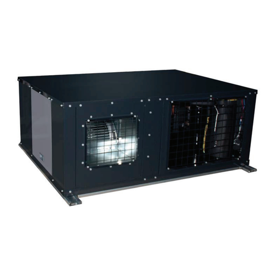
9 Servicing Cabinet description 9.2 Cabinet description General view Stop valve protection cover Back service cover Electrical box Upper cover service cover Cycle service cover Air inlet panel Fan service cover Air outlet panel Front side view Right side view Stop valve protection cover Cycle service cover Air outlet panel... -
Page 158: Removing Components
9 Servicing Removing components 9.3 Removing components 9.3.1 Removing cycle service cover 1 Unscrew the 3 fixing screws. 2 Slide the service cover upward. Then, pull backwards and remove it using the handle. Screws 9.3.2 Removing fan service cover 1 Unscrew the 3 fixing screws. 2 Slide the service cover upward. -
Page 159: Removing Stop Valve Protection Cover
9 Servicing Removing components 9.3.5 Removing stop valve protection cover Stop valves are located at the right side of RASC units, Gas stop valve next to the cycle service cover. Screws RASC units are factory-supplied with the stop valve protection cover. Before connecting refrigerant piping, the stop valve protection cover shall be removed: 1 Unscrew the 4 fixing screws. -
Page 160: Removing Air Outlet Panel
9 Servicing Removing components 9.3.8 Removing air outlet panel 1 Unscrew the 3 fixing screws which attach the air outlet Screws of the upper cover panel with the upper cover. 2 Unscrew the 12 screws, 3 for each side of the air outlet panel. -
Page 161: Removing Fan Motor
9 Servicing Removing components 9.3.9 Removing fan motor The procedure to remove the fan motor is different depending to the fan unit position (factory-supplied position or optional position). Factory-supplied position If fan unit position is factory-supplied position, follow these steps: Air outlet panel and fan unit (factory-supplied position) Upper cover Fan service cover... - Page 162 9 Servicing Removing components 2 Disconnect the electric connection of the fan Fan motor connection motor: From the fan service cover, open the fan motor connection box. 4 screws shall be loosened to remove the cover. From the fan motor connection box, disconnect all the wiring corresponding to the connections of the fan motor terminal.
- Page 163 9 Servicing Removing components In RASC-<(4-6) HP units, it may happens Earth Screw some obstruction due the electric box. Then, proceed to remove the electric box from the fan unit as shown in the pictures. Screws Gently but firmly, pull the motor support backwards.
- Page 164 9 Servicing Removing components Optional position If there is enough space for this operation from the front side of the unit, follow the instructions described in section from fan service cover. If there is not enough space for this operation from the front side of the unit, follow the instructions described in section from back service cover.
- Page 165 9 Servicing Removing components 2 Unscrew the 4 fixing nuts of the fan unit feet: From the fan service cover, unscrew the 2 nuts of one of the fan unit side feet. Nuts From the back service cover, unscrew the 2 nuts of the other fan unit side foot.
- Page 166 9 Servicing Removing components 5 Lift the fan unit up slightly, turn it until the electrical box is accessible from the back Clamps service cover. C A U T I O N When lifting the fan unit up, at least two people are required (one from each side).
- Page 167 9 Servicing Removing components Disconnect all the wiring corresponding to the connections of the fan motor terminal. Fan motor terminal strip Unscrew and pull the screwed cable gland Screwed cable gland to release the wiring harness. N O T E Remember how the cables are connected, in order to avoid possible connection problems.
- Page 168 9 Servicing Removing components In RASC-(4-6) HP units, it may happens Earth Screw some obstruction due the electric box. Then, proceed to remove the electric box from the fan unit as shown in the pictures. Screws Gently but firmly, pull the motor support backwards.
-
Page 169: Replacement Of The Compressor
9 Servicing Removing components 9.3.10 Replacement of the compressor 1 In order to access to the unit’s internal parts, remove the following covers depending on access restrictions: a. Remove the cycle service cover as described in section “9.3.1 Removing cycle service cover”. - Page 170 9 Servicing Removing components 6 Remove the suction pipe and discharge pipe from compressor. Suction Pipe N O T E Cut here • Compressor piping are connected by brazing. MAKE SURE that any flammable material is not around before heating with burner for the oil inside the piping may flame up.
- Page 171 9 Servicing Removing components 7 Remove the 4 nuts fixing the compressor and remove the compressor. When doing this, pay special attention not to touch or deform the surrounding pipes. N O T E If the upper cover had not been removed, lift it to facilitate the removal of the compressor. To lift the upper cover, proceed as described in section “9.3.6 Removing upper cover”...
-
Page 172: Replacement Of The Pressure Protection Devices
9 Servicing Removing components 9.3.11 Replacement of the pressure protection devices 1 In order to access to the unit’s internal parts, remove the following covers and panels depending on access restrictions: a. If upper cover can be removed, remove it as described in section “9.3.6 Removing upper cover”... -
Page 173: Replacement Of The Reversing Valve Coil
9 Servicing Removing components 9.3.12 Replacement of the reversing valve coil 1 In order to access to the unit’s internal parts, remove the following covers and panels depending on access restrictions: a. If upper cover can be removed, remove it as described in section “9.3.6 Removing upper cover”... -
Page 174: Replacement Of The Expansion Valve Coil
9 Servicing Removing components 9.3.13 Replacement of the expansion valve coil 1 In order to access to the unit’s internal parts, remove the following covers and panels depending on access restrictions: a. If upper cover can be removed, remove it as described in section “9.3.6 Removing upper cover”... -
Page 175: Replacement Of The Reversing Valve
9 Servicing Removing components 4 When reassembling after replacing the solenoid valve Solenoid valve coil (SVA) Solenoid valve coil screw coil, perform the procedure in the reverse order of removing. N O T E Fix the wires by plastic bands to the original position. Solenoid valve coil (SVC) 9.3.15 Replacement of the reversing valve 1 In order to access to the unit’s internal parts, remove the following covers and panels depending on access... -
Page 176: Replacement Of The Expansion Valve And Solenoid Valves (Sva, Svc)
9 Servicing Removing components 9.3.16 Replacement of the expansion valve and solenoid valves (SVA, SVC) 1 In order to access to the unit’s internal parts, remove the following covers and panels depending on access restrictions: a. If upper cover can be removed, remove it as described in section “9.3.6 Removing upper cover”... -
Page 177: Removal Of The Electrical Components (For 4-6 Hp)
9 Servicing Removing components 9.3.17 Removal of the electrical components (for 4-6 HP) D A N G E R Electrical hazard. Risk of death. • Do not touch the electrical components when LED1 (Red) of PCB1 or LED201 (Red) of DIP-IPM are ON in order to avoid an electrical shock. - Page 178 9 Servicing Removing components Upper level Upper level is accessible by only removing the electrical box service cover as described in section “9.3.3 Removing electrical box service cover”. PCB1 PCB3 Mark Part name PCB1,3 Printed circuit boards 1,3 Terminal board Removal of PCB’s (PCB1, PCB3) (PCB1) 1 Disconnect all the connectors in the PCB.
- Page 179 9 Servicing Removing components Removal of the terminal board (TB1) 1 Disconnect the power supply cables and the transmitting cables. 2 Unscrew the 2 screws and remove the terminal board. Screws Removal of the variable frequency driver (VFD) 1 The control cables are located underneath the VFD cover. To remove the VFD cover, remove previously the network cable, and then, loosen the screw at the right side of the Network...
- Page 180 9 Servicing Removing components 3 Disconnect the rest of the connected cables. Main supply cables (L1, L2 and L3). Alarm cables. Alarm cables Main supply cables 4 Remove the VFD by unscrewing the 4 screws which fix the Screws VFD to the plate. SMGB0091 rev.2 - 11/2015...
- Page 181 9 Servicing Removing components Lower level D A N G E R Electrical hazard. Risk of death. • Do not touch the electrical components when LED1 (Red) of PCB1 or LED201 (Red) of DIP-IPM are ON in order to avoid an electrical shock.
- Page 182 9 Servicing Removing components Removal of the inverter PCB (DIP-IPM) D A N G E R Electrical hazard. Risk of death. • Do not touch the electrical components when the LED201 (Red) of DIP-IPM is ON in order to avoid an electrical shock. •...
- Page 183 9 Servicing Removing components Removal of the reactor (DCL) 1 Disconnect the wires connected with the DCL. 2 Remove the 4 screws fixing the DCL and remove it. Screws Removal of the magnetic contactor for Screws compressor (CMC) 1 Disconnect the wires connected to the CMC. 2 Remove the 2 screws fixing the CMC and remove it.
- Page 184 9 Servicing Removing components Removal of the power fuses (EF1~4) Replace the fuses pulling up them from the fuse holder. Power fuses Removal of the fuse holder Fuses Screw for fuse wiring Fuse holder Remove the fuse holder removing the screw. There is 1 screw for each fuse holder.
-
Page 185: Removal Of The Electrical Components (For 8/10 Hp)
9 Servicing Removing components 9.3.18 Removal of the electrical components (for 8/10 HP) D A N G E R Electrical hazard. Risk of death. • Do not touch the electrical components when LED1 (Red) of PCB1 or LED201 (Red) of PCB4 are ON in order to avoid an electrical shock. - Page 186 9 Servicing Removing components Upper level Upper level is accessible by only removing the electrical box service cover as described in section “9.3.3 Removing electrical box service cover”. PCB1 PCB3 PCB2 Mark Part name PCB1,2,3 Printed circuit boards 1, 2 and 3 Terminal board Removal of PCB’s (PCB1, PCB2 and PCB3) (PCB1)
- Page 187 9 Servicing Removing components Removal of the terminal board (TB1) 1 Disconnect the power supply cables and the transmitting cables. 2 Unscrew the 2 screws and remove the terminal board. Screws Removal of the variable frequency driver (VFD) 1 The control cables are located underneath the VFD cover. To remove the VFD cover, remove previously the network cable, and then, loosen the screw at the right side of the Network...
- Page 188 9 Servicing Removing components 3 Disconnect the rest of the connected cables. Main supply cables (L1, L2 and L3). Alarm cables. Alarm cables Main supply cables 4 Remove the VFD by unscrewing the 4 screws which fix the Alarm connectors VFD to the plate.
- Page 189 9 Servicing Removing components Lower level D A N G E R Electrical hazard. Risk of death. • Do not touch the electrical components when LED1 (Red) of PCB1 or LED201 (Red) of DIP-IPM are ON in order to avoid an electrical shock.
- Page 190 9 Servicing Removing components Removal of the Inverter PCB(PCB4) and the inverter power module (IPM) D A N G E R Electrical hazard. Risk of death. • Do not touch the electrical components when the LED201 (Red) of DIP-IPM is ON in order to avoid an electrical shock. •...
- Page 191 9 Servicing Removing components Removal of the noise filter (NF1) 1 Disconnect all the wires connected to the noise filter (NF1). 2 Remove the noise filter by pressing the expanded part of the 4 plastic holders, using long-nose pliers, as shown in the picture below.
- Page 192 9 Servicing Removing components Removal of the magnetic contactor for fan Screws (CMF) 1 Disconnect the wires connected to the CMF. 2 Remove the 2 screws fixing the CMF and remove it. Removal of the capacitors (CB1, CB2) 1 Disconnect all the wires connected to the capacitors (CB1, CB2).
- Page 193 9 Servicing Removing components Removal of the power fuses (EF1~4) Replace the fuses pulling them up from the fuse holder. Power fuses Removal of the fuse holder Fuse holder Fuse holder screw Remove the fuse holder removing the screw. There is 1 screw for each fuse holder.
-
Page 195: Troubleshooting
10 Troubleshooting 1 0 . T r o u b l e s h o o t i n g Index 10.1 Initial troubleshooting .......................... 186 10.1.1 Checking using the 7-segment display ...................... 186 10.1.2 Failure of the power supply to the indoor unit and the remote control switch ........... 187 10.1.3 Abnormal transmission between the remote control switch and the indoor unit ........ -
Page 196: Initial Troubleshooting
10 Troubleshooting Initial troubleshooting 10.1 Initial troubleshooting 10.1.1 Checking using the 7-segment display Simple checking procedure using the 7-segment display 1 Turn on all the indoor units which are connected to the RASC unit. 2 Turn on the RASC unit 3 Auto-addressing starts. -
Page 197: Failure Of The Power Supply To The Indoor Unit And The Remote Control Switch
10 Troubleshooting Initial troubleshooting 10.1.2 Failure of the power supply to the indoor unit and the remote control switch • The LED and the LCD are not indicated. • Not operated If the fuses are blown out or a breaker is activated, investigate the cause of the overcurrent and take the necessary action. -
Page 198: Abnormal Transmission Between The Remote Control Switch And The Indoor Unit
10 Troubleshooting Initial troubleshooting 10.1.3 Abnormal transmission between the remote control switch and the indoor unit • RUN LED on the remote control switch: Flickering every 2 seconds. Action Phenomenon Cause Check item (Turn OFF the main switch) Disconnection or insufficient contacting of the remote control Check the cable and the Repair the cable or connect the cable... - Page 199 10 Troubleshooting Initial troubleshooting Action Phenomenon Cause Check item (Turn OFF the main switch) Failure of thermistor Failure of air Replace or correctly connect inlet thermistor Disconnec tion of Check it by self-checking *1) the wires if abnormal operation thermistor exists Abnormal operation of the remote control switch cord...
- Page 200 10 Troubleshooting Initial troubleshooting Action Phenomenon Cause Check item (Turn OFF the main switch) Failure of the Failure of the thermistor discharge air Check the thermistor using Replace or correctly connect Disconnected temperature the self-check mode *1) the wiring when it is abnormal wire of the thermistor Indoor fan speed does not...
- Page 201 10 Troubleshooting Initial troubleshooting Action Phenomenon Cause Check item (Turn OFF the main switch) Indoor cool load is greater than the Calculate the cool load Use a bigger unit cooling capacity Gas leakage Correctly charge the refrigerant or shortage of Measure superheat after repairing the gas leakage refrigerant...
- Page 202 10 Troubleshooting Initial troubleshooting Action Phenomenon Cause Check item (Turn OFF the main switch) Clogging of the RASC unit Remove the clogging heat exchanger? Obstacles at the inlet or the Insufficient outlet of the RASC unit heat Remove the obstacles air flow to the exchanger RASC unit heat...
- Page 203 10 Troubleshooting Initial troubleshooting Action Phenomenon Cause Check item (Turn OFF the main switch) Indoor heat load is greater than the Replace the unit with a bigger Calculate the heat load heating capacity unit Gas leakage Correctly charge the refrigerant or insufficient Measure superheat after the gas leakage check...
- Page 204 10 Troubleshooting Initial troubleshooting Action Phenomenon Cause Check item (Turn OFF the main switch) Check the filter for a clogging Remove the clogging Insufficient Check for any obstacles at air flow to the the inlet or the outlet of the Remove the obstacles indoor unit heat indoor unit...
- Page 205 10 Troubleshooting Initial troubleshooting Action Phenomenon Cause Check item (Turn OFF the main switch) Obstacle at the RASC fan Check the obstacles Remove the obstacles RASC fan does not operate If the 4-way valve does not when the compressor Watching condition for the heating Wait for the switching of the switch, check for insufficient operates...
-
Page 206: Troubleshooting Procedure
10 Troubleshooting Troubleshooting procedure 10.2 Troubleshooting procedure 10.2.1 On-screen displays during abnormal operation PC-ART PC-ARF 01-02 Alarm Code: MODEL : b .02 Flickering ALM RST ADDR SEL. OP MODE ENT. Abnormal operation can be produced due to the following reasons: ... -
Page 207: Alarm Codes
10 Troubleshooting Troubleshooting procedure 10.2.2 Alarm codes • The RUN LED flickers and “ALARM” is displayed on the remote control switch. • The unit number, the alarm code and the unit code are alternately displayed on the set temperature section. •... - Page 208 10 Troubleshooting Troubleshooting procedure Code Category Type of abnormality Main cause number Overload (obstruction of HEX, short circuit) mixture Activation of the safety device from excessively of inert gas, excessive refrigerant or faulty RASC fan high discharge pressure motor. Activation of the safety device from excessively Protection Shortage or leakage of refrigerant, piping clogging, low suction pressure (protection from vacuum...
-
Page 209: Troubleshooting By Alarm Code
10 Troubleshooting Troubleshooting procedure 10.2.3 Troubleshooting by alarm code Alarm code Activation of the safety device (flow switch) in the indoor unit (except RPK series) This alarm code is displayed when the contact between #1 and #2 of CN14 is not closed over 120 seconds during the cooling process, the heating process or the fan operation. - Page 210 10 Troubleshooting Troubleshooting procedure Alarm code Activation of the safety device (flow switch) in the indoor unit (RPK only) Indication of Outdoor Unit PCB Alarm code Indoor Unit number for Malfunction Turn OFF the power Is alarm code “01” Is DSW2-1P on OU source and then turn indicated on LCD or PCB ON?
- Page 211 10 Troubleshooting Troubleshooting procedure Alarm code Activation of the safety device in the RASC unit This alarm is indicated when one of safety devices is activated during compressor running. Is the voltage 230V Does CMC or existing at the #1 to Is the protective CMF turn ON when Faulty PCB1.
- Page 212 10 Troubleshooting Troubleshooting procedure Action Phenomenon Cause Check item (Turn OFF the main switch) High level of Clogging of the Remove the clogged foreign condensed water Check the drain piping drainage particles in the drain pan Check the continuity when the Activation of the Faulty float switch Replace the float switch if faulty...
- Page 213 10 Troubleshooting Troubleshooting procedure Action Phenomenon Cause Check item (Turn OFF the main switch) Check if the heat exchanger Remove the dust or strange is clogged (by dust or any particles strange particle) Clogging of the heat exchanger Check for any obstacles at the inlet or the outlet of the heat Remove the obstacles exchanger...
- Page 214 10 Troubleshooting Troubleshooting procedure Action Phenomenon Cause Check item (Turn OFF the main switch) Reduce the heat load or use a Calculate the heat load bigger unit if possible Check for hot air near the Provide good circulation ceiling (heating) Excessively high temperature air to the indoor unit during heating mode Check for short-circuited air...
- Page 215 10 Troubleshooting Troubleshooting procedure Alarm code Abnormal transmission between the indoor units and the RASC unit • This alarm is displayed when abnormal operation is maintained for three minutes after normal transmission has been confirmed between the indoor units and the RASC unit. Also, when abnormal operation continues for 30 seconds after the micro-computer is automatically reset.
- Page 216 10 Troubleshooting Troubleshooting procedure RASC-(4-6)HNPE RU: RASC unit IU: Indoor unit Is DSW5-1P (Terminating resistance) on RU PCB1 Set it correctly Is there 400V between Is LED4 (red) RASC Check power source for phases L1/L2/L3 of the RASC unit (ELB, etc.) RU PCB1 ON? terminal board? (AC power is not coming to the PCB)
- Page 217 10 Troubleshooting Troubleshooting procedure RASC-(8/10)HNPE RU: RASC unit IU: Indoor unit Is DSW5-1P (Terminating resistance) on RU PCB1 Set it correctly Is there 400V between Check power source for Is LED4 (red) RASC phases L1/L2/L3 of the RASC unit (ELB, etc.) RU PCB1 ON? terminal board? (AC power is not coming to the PCB)
- Page 218 10 Troubleshooting Troubleshooting procedure Action Phenomenon Cause Check item (Turn OFF the main switch) Measure the voltage Power failure or no power supply Supply power using the tester Remove cause of short circuit. Check for breakage of Short circuit between wires Replace fuse and/or indoor/ insulation RASC unit PCB if faulty...
- Page 219 10 Troubleshooting Troubleshooting procedure N O T E • *1) In the case that the end terminal resistance (DSW5-1) is set to OFF for H-LINK connection, set the end terminal resistance to ON when CN8 is disconnected. Set the end terminal resistance to OFF when CN8 is reconnected. •...
- Page 220 10 Troubleshooting Troubleshooting procedure Alarm code Abnormal transmission between Inverter PCB and RASC PCB1 This alarm is displayed when the abnormal operation is maintained for 30 seconds after the normal transmission between the control PCB and the inverter PCB on RASC unit. Also, the abnormal operation is maintained for 30 seconds after the micro-computer is automatically reset.
- Page 221 10 Troubleshooting Troubleshooting procedure RASC-(8/10)HNPE Are the fuse (EF1) Repair fuse if blown on PCB1 and power fuses (EF1,EF2) normal? N O T E Investigate the cause of fuse blown. Is wiring between CN6 on Check the wiring and repair it the PCB1 and CN206 on the (Broken or wrong wiring) PCB4 correctly connected?
- Page 222 10 Troubleshooting Troubleshooting procedure Alarm code Code abnormal operation of picking up phase signal This alarm is displayed when the main power source phase is reversely connected or one phase is not connected. Is there any phase which is Correctly connect each not connected? phase of the power source PCB1 is normal...
- Page 223 10 Troubleshooting Troubleshooting procedure Alarm code Excessively low voltage or excessively high voltage for the inverter PCB This alarm code is displayed when the voltage of DIP-IPM is insufficient or excessive and the alarm has three occurrences in 30 minutes. If the number of occurrences is smaller than two, the retry operation is performed. RASC-(4-6)HNPE Restart the operation Is the power...
- Page 224 10 Troubleshooting Troubleshooting procedure RASC-(8/10)HNPE Restart the operation Is the power Check wiring and supply voltage cable capacity 400V±10%? Is the power supply voltage 323V during operation? Does the voltage fall during operation by operation of Fault magnetic other apparatus? contactor.
- Page 225 10 Troubleshooting Troubleshooting procedure Alarm code Decrease of discharge gas superheat • When the temperature at the top of compressor remains lower than the condensing temperature during 30 continuous minutes, the compressor stops and performs a retry operation 3 minutes later. If this occurs 2 more times within 120 minutes, an alarm code is shown.
- Page 226 10 Troubleshooting Troubleshooting procedure Action Phenomenon Cause Check item (Turn OFF the main switch) Refrigerant cycle is different from the electrical Check refrigerant cycle Repair wiring system and the electrical system Overcharged refrigerant Measure pressure Correctly charge refrigerant Check expansion valve Replace expansion valve if Faulty expansion valve (*1)
- Page 227 10 Troubleshooting Troubleshooting procedure Alarm code Excessively high discharge gas temperature at the top of compressor • The alarm appears during cooling operation when the compressor-top thermistor temperature remains at Tdc1 or above for 10 minutes, or at Tdc2 or above for 5 seconds. •...
- Page 228 10 Troubleshooting Troubleshooting procedure Abnormal operation of thermistor for the indoor unit air inlet temperature Alarm code (air inlet thermistor) This alarm code is displayed when the thermistor is short-circuited (less than 0.24 kΩ) or cut (greater than 840 kΩ) during the cooling process or the heating process.
- Page 229 10 Troubleshooting Troubleshooting procedure Abnormal operation of the thermistor for the indoor discharge air temperature Alarm code (air outlet thermistor) This alarm code is displayed when the thermistor is short-circuited (less than 0.24 kΩ) or cut (greater than 840 kΩ) during the cooling process or the heating process.
- Page 230 10 Troubleshooting Troubleshooting procedure Abnormal operation of the thermistor for the indoor unit heat exchanger liquid pipe Alarm code temperature (freeze protection thermistor) This alarm code is displayed when the thermistor is short-circuited (less than 0.24 kΩ) or cut (greater than 840 kΩ) during the cooling process or the heating process.
- Page 231 10 Troubleshooting Troubleshooting procedure Abnormal operation of the thermistor for the indoor unit heat exchanger gas pipe Alarm code temperature (gas piping thermistor) This alarm code is displayed when the thermistor is short-circuited (less than 0.24 kΩ) or cut (greater than 840 kΩ) during the cooling process or the heating process.
- Page 232 10 Troubleshooting Troubleshooting procedure Alarm code Abnormal operation of thermistor for fresh outdoor air (Econofresh) • The RUN LED flickers and “ALARM” is displayed on the remote control switch. • The unit number, the alarm code and the unit code are alternately displayed on the set temperature section. The unit number and the alarm code are displayed on the display of the RASC unit PCB.
- Page 233 10 Troubleshooting Troubleshooting procedure Activation of the protection device for the indoor fan motor (except RCI-FSN3, RCIM- Alarm code FSN3, RPC-FSN3 and RPK) This alarm code is displayed when the temperature of the internal thermostat for the indoor fan motor is higher than 135 ºC. Is the continuity present at the Does the indoor Is the fan motor...
- Page 234 10 Troubleshooting Troubleshooting procedure Activation of the protection device for the indoor fan motor (RCI-FSN3, RCIM-FSN3, Alarm code RPC-FSN3) This alarm code is displayed when the following conditions occurs three times in 30 minutes. Indoor fan rotates less than 70 rpm for 5 seconds during operation. (*)When the cause is checked by means of this flow chart, confirm that fan speed setting is Hi.
- Page 235 10 Troubleshooting Troubleshooting procedure Alarm code Activation of the protection device for the indoor fan motor (RPK) This alarm code is displayed when the following conditions occurs three times in 30 minutes. Indoor fan rotates less than 70 rpm for 5 seconds during operation. •...
- Page 236 10 Troubleshooting Troubleshooting procedure Alarm code Abnormality of thermistor for discharge gas temperature (THM9) (Compressor thermistor) This alarm code is indicated when the thermistor is short-circuited (less than 1 kΩ) or cut (greater than 6 MΩ) during the cooling or heating operation. Compressor-top thermistor (THM9) Is the thermistor connected to...
- Page 237 10 Troubleshooting Troubleshooting procedure Alarm code Abnormality of high pressure sensor This alarm code is indicated when the pressure sensor output voltage decreases (less than 0.1V) or increases (more than 4.9V) during the operation. Is there connection problem of Connect correctly CN100 on RASC PCB1? Is 12V applied between number Faulty RASC PCB1...
- Page 238 10 Troubleshooting Troubleshooting procedure Abnormal operation of the thermistor for the outdoor temperature (THM7) Alarm code (RASC unit ambient thermistor) This alarm code is displayed when the thermistor is short-circuited (less than 0.2 kΩ) or cut (greater than 500 kΩ) during the operation.
- Page 239 10 Troubleshooting Troubleshooting procedure Abnormal operation of the thermistor for the evaporating temperature during the heating Alarm code process (THM8) (RASC unit) If you find an abnormal operation of the thermistor, check all the thermistors as shown below. • The evaporating thermistor during the heating process is attached to the heat exchanger as shown in the figure below.
- Page 240 10 Troubleshooting Troubleshooting procedure Alarm code Incorrect capacity setting or combined capacity between indoor units and RASC unit • This alarm code is indicated when the undefined setting is set to DSW3 on the RASC unit PCB. • This alarm code is indicated when the total indoor unit capacity is outside the range allowed of the combined RASC unit capacity.
- Page 241 10 Troubleshooting Troubleshooting procedure Alarm code Incorrect Indoor number setting This alarm code appears under any of the following conditions: • Wrong indoor unit address (DSW6 + RSW1) • Duplicated RASC unit refrigerant system setting or wrong refrigerant system DSW settings (DSW4 + RSW1). •...
- Page 242 10 Troubleshooting Troubleshooting procedure Alarm code Abnormality of protective circuit for protection (RASC unit) The alarm code appears if 1~ 230V is supplied to the connector on the RASC unit PCB1 while Y52C (Compressor relay open) is OFF or CMC (Magnetic contactor for compressor) or CMF (Magnetic contactor for fan motor) are open. Is 1~ 230V applied Faulty RASC PCB1 between PCN9 number 1...
- Page 243 10 Troubleshooting Troubleshooting procedure Alarm code Activation of high pressure increase protection device When the compressor operates with the discharge pressure (Pd) higher than 3.8 MPa for 1 minute, the retry operation is performed 3 minutes after compressor is stopped. Thereafter, this alarm code is indicated when above abnormality is detected twice in 30 minutes.
- Page 244 10 Troubleshooting Troubleshooting procedure Activation to protect system from excessively low suction pressure Alarm code (Protection from vacuum operation) In the case that the evaporating temperature (Cooling: liquid refrigerant piping temperature of indoor unit; Heating: evaporating temperature of RASC unit) is lower than -37 ºC (250~350 kΩ) and the thermistor temperature on top of compressor is higher than 90 ºC for 3 minutes, retry operation is performed 3 minutes after compressor stoppage.
- Page 245 10 Troubleshooting Troubleshooting procedure Alarm code Overcurrent protection activation It trips Turn OFF power and disconnect immediately U, V, W from compressor Is there any cause of Check the terminals. Turn ON number 1 of Restart operation. instantaneous voltage compressor DSW1 on DIP-IPM (4-6HP) or PCB4 Does it trip soon? decrease?
- Page 246 10 Troubleshooting Troubleshooting procedure Alarm code Abnormal operation of the current sensor (RASC-(4-6)HNPE) • This alarm code is displayed when the current transformer is abnormal (0 A detection or 5 A alarm condition) and the alarm has more than three occurrences in 30 minutes. •...
- Page 247 10 Troubleshooting Troubleshooting procedure Alarm code Abnormal operation of the current sensor (RASC-(8/10)HNPE) • This alarm code is displayed when the current transformer is abnormal (0 A detection or 5 A alarm condition) and the alarm has more than three occurrences in 30 minutes. •...
- Page 248 10 Troubleshooting Troubleshooting procedure Alarm code Protection activation of inverter module (RASC-(4-6)HNPE) The inverter PCB (DIP-IPM) has a function of abnormality detection. This alarm is indicated when the inverter module detects the abnormality 7 times in 30 minutes including 7. Retry operation is performed up to the occurrence of 6 times. Conditions: •...
- Page 249 10 Troubleshooting Troubleshooting procedure Alarm code Protection activation of transistor module (IPM) (RASC-(8/10)HNPE) IPM has a function of abnormality detection. This alarm is indicated when the transistor module detects the abnormality 7 times in 30 minutes including 7. Retry operation is performed up to the occurrence of 6 times. Conditions: •...
- Page 250 10 Troubleshooting Troubleshooting procedure Alarm code Abnormality of inverter fin temperature (RASC-(4-6)HNPE) This alarm code is indicated after the operation is stopped when the following condition occurs three times within 30 minutes. The retry operation is performed twice. Conditions: • When the temperature inside the transistor module of the inverter PCB exceeds 90 °C.
- Page 251 10 Troubleshooting Troubleshooting procedure Alarm code Abnormality of inverter fin temperature (RASC-(8/10)HNPE) This alarm code is indicated after the operation is stopped when the following condition occurs three times within 30 minutes. The retry operation is performed twice. Conditions: • When the temperature of the thermistor for inverter fin exceeds 100 °C.
- Page 252 10 Troubleshooting Troubleshooting procedure Alarm code Abnormality of Inverter PCB • Actual frequency from Inverter PCB is less than 10 Hz (after inverter frequency output form PCB1 to Inverter PCB). • This alarm is displayed when it occurs 3 times in 30 minutes. Retry operation is performed up to the occurrence of 2 times.
- Page 253 10 Troubleshooting Troubleshooting procedure Alarm code Compressor protection This alarm code is displayed when one of the following alarms occurs three times within six hours. If the RASC unit operates continuously without removing the cause of the alarm, the compressor may be seriously damaged Alarm code Content of abnormality Tripping of protection device in RASC unit...
- Page 254 10 Troubleshooting Troubleshooting procedure Alarm code Incorrect setting of unit and refrigerant cycle number This alarm code is indicated in the following condition. Check the settings of the dip switch (DSW) and the rotary switch (RSW) after turning OFF the power source. Conditions Action Unit number setting / refrigerant cycle number setting starting...
-
Page 255: Troubleshooting In Check Mode
10 Troubleshooting Troubleshooting in check mode 10.3 Troubleshooting in check mode 10.3.1 Troubleshooting using the remote controller PC-ART Use the “OK” switch of the remote control in the following cases: 1 When the RUN LED is flickering. 2 To trace back the cause of the malfunction after restarting from the stoppage while the RUN LED is flickering. - Page 256 10 Troubleshooting Troubleshooting in check mode Although the wireless controller is used for the wall type indoor unit with the built-in receiver part, you can check the alarm code by connecting the PC-ART. Suction grille Connector for check N O T E •...
- Page 257 10 Troubleshooting Troubleshooting in check mode Indication of micro-computer input/output Heating Thermo-ON Micro-computer input/output in C1 indoor unit Alarm Cooling Thermo-ON Dark Micro-computer input/output in C2 - RASC unit Y52C2 Y211 Y212 Y52C1 Dark Y20B Y20A RASC fan (Symbols with the letter Y are relays on the PCB) Indication of unit stoppage cause d1 01 14 Cause of stoppage...
- Page 258 10 Troubleshooting Troubleshooting in check mode Abnormal operation occurrence counter Abnormal operation occurrence E1 01 counter Countable up to 99. Over 99 times, “99” is always displayed. Instantaneous power failure E2 00 occurrence counter in indoor unit N O T E Transmission error occurrence •...
- Page 259 10 Troubleshooting Troubleshooting in check mode Expansion opening indication Indoor unit expansion valve L1 20 opening (%) RASC unit expansion valve MV L2 gg opening (%) L3 gg 30 Same as line 29. L4 00 31 Control information Estimated electric current indication The running current of the primary side of the inverter is P1 25 32 Compressor running current (A)
- Page 260 10 Troubleshooting Troubleshooting in check mode Contents of the check mode 2 When more than three indoor units are connected to one remote control switch, the latest data of only the first three indoor units that are connected serially are displayed. If you press the part “”...
- Page 261 10 Troubleshooting Troubleshooting in check mode Self-checking procedure of PCB by means of the remote control switch Use the following troubleshooting procedure for testing the PCB in the indoor unit and the RASC unit: Press Stop operation Press both switches for three seconds PCB check mode Indication...
- Page 262 10 Troubleshooting Troubleshooting in check mode From previous page If there is a next unit Press Press (Self-checking indication of the next unit) (Repetition of self-checking (ex.) Indication of of unit number “1”) unit Number “2” After 7 seconds After 1 to 5 seconds Result After 1 second Repeat...
- Page 263 10 Troubleshooting Troubleshooting in check mode Self-checking procedure of the remote control switch Cases where the OK switch is used: 1 If the remote control switch displays a malfunction. 2 For the regular maintenance check. Indicating Turn ON the power source Nº...
- Page 264 10 Troubleshooting Troubleshooting in check mode The LCD changes as shown below. The detected temperature of the remote control thermostat is displayed at the (A) part in the figure below. If the indicators “ ” or “ ” are displayed at the “A” part, the remote control thermostat is abnormal.
-
Page 265: Troubleshooting Using The Remote Controller Pc-Arf
10 Troubleshooting Troubleshooting in check mode 10.3.2 Troubleshooting using the remote controller PC-ARF Each “Check Menu” item and its function is explained in the following table. Check Menu item Function Check 1 Sensor condition of air conditioner will be monitored and indicated. Check 2 Sensor data of air conditioner prior to alarm occurrence will be indicated. - Page 266 10 Troubleshooting Troubleshooting in check mode Items of Check mode 1 Nº Item Data Name Nº Item Data Name Set Temperature Times of Abnormal Transmitting Inlet Air Temperature Times of Inverter Tripping Discharge Air Temperature Louvre Sensor State Liquid Pipe Temperature Discharge Pressure Remote Thermistor Temperature Suction Pressure...
- Page 267 10 Troubleshooting Troubleshooting in check mode Alarm history display The alarm history display can be set from the check menu. (1) Press and hold “ ” (menu) and “?” (help) simultaneously for 3 Check Menu seconds during the normal mode. Check 1 The check menu is displayed.
- Page 268 10 Troubleshooting Troubleshooting in check mode Checking procedure of PCB by means of the remote control switch Check Menu (1) Press and hold “ ” (menu) and “?” (help) simultaneously for 3 I. U./O. U. PCB Check seconds during the normal mode. The check menu is displayed.
- Page 269 10 Troubleshooting Troubleshooting in check mode Self-checking procedure of the remote control switch The self checking performs to check the remote control switch and to clear EEPROM (storage cell inside of the remote control switch). (1) Press and hold “ ” (menu) and “?” (help) simultaneously for 3 Check Menu seconds during the normal mode (when unit is not operated).
- Page 270 10 Troubleshooting Troubleshooting in check mode (9) No Function 07: No function This function is not used. 08: Transmission test Press “OK” to proceed. Self Checking (10) Transmission Circuit Test 0 7 : 0 0 0 The remote control switch automatically starts to check the transmission circuit. (11) Remote Control Switch Thermistor Test Self Checking The temperature detected by remote control switch thermistor is displayed at...
-
Page 271: Troubleshooting Using The 7 Segment Display
10 Troubleshooting Troubleshooting in check mode 10.3.3 Troubleshooting using the 7 segment display Simple checking by 7-segment display During auto-addressing, the following items can be checked using the Turn ON indoor unit connected to RASC unit’s on-board 7-segment LED display: the RASC unit 1 Disconnection of power supply to the indoor unit. - Page 272 10 Troubleshooting Troubleshooting in check mode Item Indication data Item Check Indic. Indic. Contents number Input/output state of RASC micro- Indicates only for the segments corresponding to the equipment in the computer figure. (See figure above (*1)) 00~199 oP 11 Total capacity of operating indoor unit In case that capacity is higher than 100, the last two digits flash.
- Page 273 10 Troubleshooting Troubleshooting in check mode Cause of indoor unit stoppage ( Indication Contents Operation OFF, Power OFF N O T E Thermo-OFF, float switch activation (NOTE 1) • Demand thermo OFF: Temperature Area in Heating Operation Alarm (NOTE 2) Thermo-OFF temperature area Freeze protection, overheating protection Instantaneous power failure at RASC unit (NOTE 3)
- Page 274 10 Troubleshooting Troubleshooting in check mode i Cause of inverter stoppage ( Remark Cause of stoppage Code Cause for corresponding Indication Alarm Code unit during retry Fault signal error of inverter module (DIP-IPM/IPM Error) (Overcurrent, Undercurrent, Temperature increase, etc.) Instantaneous overcurrent Abnormal inverter fin temperature Electronic thermal activation (Inverter overcurrent)
- Page 275 10 Troubleshooting Troubleshooting in check mode Protection control code on 7-segment display 1 Protection control code is displayed on 7-segment when a protection control is activated. 2 Protection control code is displayed while function is working, and goes out when released. 3 When several protection control are activated, code number with higher priority will be indicated (see below for the priority order).
- Page 276 10 Troubleshooting Troubleshooting in check mode Activating condition of protection control code To monitor the conditions such as the temperature change and others, the control of the frequency and other controls are performed by the protection control in order to prevent the abnormal operations. The activating conditions of protection control are shown in the table below: Code Protection control...
-
Page 277: Checking Procedure For Main Parts
10 Troubleshooting Checking procedure for main parts 10.4 Checking procedure for main parts 10.4.1 Checking procedure for the control PCB (PCB1) Turn ON RASC unit LED4 (Red) is turned Failure of AC Power Circuit Fuse EF1 is blowout of RASC PCB Connect PCN406. - Page 278 10 Troubleshooting Checking procedure for main parts Check point Normal Range (V) (+) Side of tester (-) Side of tester Approx. 311VDC VDC-2 VCC15-1 13.5VDC ~ 16.5VDC VCC05 4.5VDC ~ 5.5VDC GND1 VCC12 11.9VDC ~14.3VDC C A U T I O N •...
-
Page 279: Checking Procedure For The Inverter Pcb
10 Troubleshooting Checking procedure for main parts 10.4.2 Checking procedure for the inverter PCB RASC-(4-6)HNPE High voltage discharge work for replacing parts High voltage discharge is an imperative work for replacing parts. C A U T I O N Electrical hazard. - Page 280 10 Troubleshooting Checking procedure for main parts 5 Touch [+] of the tester to [P] of DIP-IPM (soldered part), and [-] to DIP-IPM U, V, W terminals to measure the resistance. Normal if all three terminals have 1 kΩ or greater. 6 Contrary to [5], touch [-] of the tester to [P] of DIP- IPM (soldered part), and [+] to DIP-IPM U, V, W terminals to measure the resistance.
- Page 281 10 Troubleshooting Checking procedure for main parts Checking method of resistance for inrush current prevention (Built-in thermal fuse) (Measure the resistance under 1 kΩ range of a circuit tester.) By placing the side of tester to the side of DM1 (soldering portion) on DIP-IPM and the side of tester to DCL1 DIP-IPM, measure the resistance.
- Page 282 10 Troubleshooting Checking procedure for main parts RASC-(8/10)HNPE High voltage discharge work for replacing parts C A U T I O N Electrical hazard. Risk of electrical shock. Perform this high voltage discharge work to avoid an electric shock. 1 Turn OFF the main switches and wait for three minutes.
- Page 283 10 Troubleshooting Checking procedure for main parts 4 By touching the + side of the tester to the N terminal of transistor module and the - side of tester to U, V and W of transistor module, measure the resistance. If all the resistances are greater than 100kΩ, it is normal.
- Page 284 10 Troubleshooting Checking procedure for main parts Checking capacitors CB1 and CB2 D A N G E R Electrical hazard. Risk of serious injuries or death. • Before installing the electrical wiring or before performing a periodical check, turn OFF the main switch of the unit. For safety reasons, be sure that the fan is stopped.
-
Page 285: Fault Diagnosis Of Fan Motor
10 Troubleshooting Checking procedure for main parts 10.4.3 Fault diagnosis of fan motor Some alarms may have been caused due to faulty fan motor. Therefore, check the fan motor as explained below: C A U T I O N • Turn OFF main power before start working. -
Page 286: Checking Procedure For The Electronic Expansion Valve For Indoor And Rasc Units
10 Troubleshooting Checking procedure for main parts 10.4.4 Checking procedure for the electronic expansion valve for indoor and RASC units Indoor unit electronic expansion valve RASC unit electronic expansion valve Check the liquid pipe temperature during the heating It is abnormal if the liquid pipe pressure does Locked with fully closed process. - Page 287 10 Troubleshooting Checking procedure for main parts Checking procedure for the reversing valve Troubleshooting Is the connector PCN100 Connect it correctly. *1) on PCB1 connected correctly? Reversing valve is faulty Is the resistance of the (disconnection, etc.). Replace it reversing valve coil *2) N O T E with a new one.
- Page 288 10 Troubleshooting Checking procedure for main parts Electrical circuit 4-way solenoid 4-way solenoid valve coil valve coil Time Chart Cooling operation Defrost operation Heating operation Heating operation 4-way solenoid valve Current is continuously carried while the reversing valve is ON. is turned ON Coil voltage Bistable solenoid operation type (pulse-activated)
- Page 289 10 Troubleshooting Checking procedure for main parts Electrical circuit When the reversing valve relay is turned ON, current is applied to When the reversing valve relay is turned ON, current is applied to the coil. After the reversing valve relay is turned OFF, no current the coil.
- Page 290 10 Troubleshooting Checking procedure for main parts Checking procedure for the compressor CHECK LIST ON COMPRESSOR Client: Model: Date: Serie number: Production date: Checker: Nº Check item Check method Result Remarks Is THM9 correctly connected? 1. Is wire of thermistor correctly connected by viewing? THM9: Discharge Gas Thermistor 2.
- Page 291 10 Troubleshooting Checking procedure for main parts Additional Information for “CHECK LIST ON COMPRESSOR” Check item Additional information (mechanism of the compressor failure) 1 & 2 The liquid refrigerant return volume to the compressor is controlled by the discharge gas temperature Td when compressor is operating.
-
Page 293: Maintenance Notes
11 Maintenance notes 11 . M a i n t e n a n c e n o t e s Index 11.1 General notes ............................284 11.1.1 Checking the power source and the wiring connection ................284 11.1.2 Burnt-out compressor due to an insufficient refrigerant charge ..............284 11.1.3 ... -
Page 294: General Notes
11 Maintenance notes General notes 11.1 General notes 11.1.1 Checking the power source and the wiring connection Check the following items in the case of abnormal operation: Check item Procedure Is the breaker of the fuse cut Check the secondary voltage of the breaker and the fuse by means of a tester. out? Disconnect the secondary side of the transformer and check the voltage by means of a tester. Indoor unit transformer 12 V... -
Page 295: Insufficient Cooling Performance When A Long Piping Is Applied
11 Maintenance notes General notes 11.1.3 Insufficient cooling performance when a long piping is applied Question and answer for the field work: Example 2: Insufficient cooling performance when a long piping is applied Phenomenon Sufficient cooling was not available for an indoor unit that was located at the farthest position. If the location of a RASC unit is 20 meters lower than the location of the indoor units, resetting of the DIP switch DSW2 is required. However, no setting was performed. Therefore, the largest discharge pressure was not increased. This resulted in an insufficient cooling performance for the indoor unit. Indoor units Insufficient cooling Cause RASC unit Countermeasure The setting of the DSW2 was changed. -
Page 296: Alarm Code "31
This resulted in a different setting of total indoor unit capacity in the same refrigerant cycle, causing abnormal working conditions. When the capacity of the system dropped under the minimum value, alarm 31 was activated putting the system in Thermo-OFF. To set the main switch of the indoor units to be always ON, or to install the Hitachi Multitenant building Countermeasure connection board PC-AMTB. -
Page 297: Maintenance Work
11 Maintenance notes Maintenance work 11.2 Maintenance work C A U T I O N • All inspections and checks of the RASC unit have to be carried out by a licensed technician and never by the user itself. • Before any inspection and checking procedure, the unit main power supply has to be switched OFF. -
Page 298: Service And Maintenance Record
11 Maintenance notes Service and maintenance record 11.3 Service and maintenance record Check item Action Judgement Is the service area sufficient? Is there a short circuit of the discharged air? Any heat influence? Is the ground wire connected? Refrigerant piping Good Not good Fixing the units Good Not good Is there any damage on the outer surface or the internal surface? Checking the screw and the bolts Tighten if loosened. -
Page 299: Service And Maintenance Record Using The 7-Segment Display
11 Maintenance notes Service and maintenance record using the 7-segment display 11.4 Service and maintenance record using the 7-segment display Data sheet for checking by 7-segment display Customer’s name: Date: RASC unit model (serial number) RASC- (Serial number) RASC- (Serial number) Operation mode Test run start time Data collect start time Read out data from 7-segment in RASC unit Protection control code... - Page 300 11 Maintenance notes Service and maintenance record using the 7-segment display RASC unit model (serial number) RASC- (Serial number) RASC- (Serial number) Cause of indoor unit stoppage Indoor unit address (Unit number 5) Indoor unit expansion valve opening Liquid pipe temperature of indoor unit (Freeze protection) Indoor unit intake air temperature Indoor unit discharge air temperature Cause of indoor unit stoppage Indoor unit address (Unit number 6)
-
Page 301: Service And Maintenance Record By Remote Control Switch
11 Maintenance notes Service and maintenance record by remote control switch 11.5 Service and maintenance record by remote control switch Data sheet for checking by remote control switch Time Indoor unit model Indoor unit serial number Indoor unit number / alarm code Check Check 1 · 2 1 ·... -
Page 302: Pump-Down Method For Replacing The Compressor
11 Maintenance notes Pump-down method for replacing the compressor 11.6 Pump-down method for replacing the compressor Procedure Remarks Turn off the main switch of the RASC unit. Remove the covers, the thermistor, the crankcase heater, Make sure that the terminal part of the detached power supply the power wirings, and other items according to the chapter wires is not exposed by the winding insulation tape and other ... - Page 303 11 Maintenance notes Pump-down method for replacing the compressor Procedure Remarks Make sure that there is no pressure increase of the low-pressure sides after collecting the refrigerant. After collecting the refrigerant, remove the change hose (collector side) of the low-pressure side, so that Make sure that the refrigerant cycle is the atmosphere the low-pressure side of the refrigerant cycle will be the pressure.
- Page 306 Hitachi Air Conditioning Products Europe, S.A.U. Ronda Shimizu, 1 - Políg. Ind. Can Torrella 08233 Vacarisses (Barcelona) Spain Hitachi certifies that our products have met EU consumer safety, health and environmental requirements. Hitachi Air Conditioning Products Europe, S.A.U. is certified with:...
Need help?
Do you have a question about the RASC-4HNPE and is the answer not in the manual?
Questions and answers