Sign In
Upload
Manuals
Brands
Hitachi Manuals
Air Conditioner
RASC-8HNPE
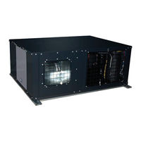
Hitachi RASC-8HNPE Manuals
Manuals and User Guides for Hitachi RASC-8HNPE. We have
4
Hitachi RASC-8HNPE manuals available for free PDF download: Service Manual, Installation & Operation Manual, Instruction Manual, Installation And Operation Manual
Hitachi RASC-8HNPE Installation & Operation Manual (275 pages)
Brand:
Hitachi
| Category:
Air Conditioner
| Size: 27 MB
Table of Contents
Table of Contents
7
General Information
14
Safety
14
Applied Symbols
15
Product Guide
16
Product Line-Up: Indoor Units
16
RCI and RCIM Indoor Units
16
RCD and RPC Indoor Units
17
RPI Indoor Units
18
RPK, RPF and RPFI Indoor Units
19
Product Line-Up: Outdoor Units
20
UTOPIA IVX X Series
20
UTOPIA Series
20
UTOPIA IVX Series
21
UTOPIA RASC Series
21
SET FREE Mini Series
21
SET FREE Standard FS(X)NSE(1) Series
22
SET FREE High Efficiency FS(X)NPE(1) Series
26
Classification of Indoor Units Model
29
Classification of UTOPIA Outdoor Unit Models
29
UTOPIA Series
29
UTOPIA RASC Series
29
Classification of SET FREE Outdoor Unit Models and CH-Box Modules
30
SET FREE Mini Series
30
SET FREE Standard FS(X)NSE(1) Series
30
SET FREE High Efficiency FS(X)NPE(1) Series
30
Box
31
Name of Parts and General Dimensions
32
Indoor Units
32
Rci-(1.0-6.0)Fsr
32
Rcim-(0.4-2.5)Fsre
33
Rcd-(0.8-3.0)Fsr
34
Rcd-(4.0-6.0)Fsr
35
Rpc-(1.5-6.0)Fsr
36
Rpil-(0.4-1.5)Fsre
37
Rpi-(1.5/2.0)Fsre
38
Rpi-(2.5-6.0)Fsre
39
Rpih-(4.0-6.0)Fsre
40
RPI-(8.0/10.0)FSN3E(-F)
41
RPI-(16.0/20.0)FSN3PE(-F)
42
Rpk-(0.4-4.0)Fsr(H)M
43
Rpf-(1.0-2.5)Fsn2E
44
Rpfi-(1.0-2.5)Fsn2E
45
Outdoor Units
46
Ras-3Hvrc2
46
Ras-(4-6)H(V)(R/N)(C/P)2E
47
Ras-(4-6)(X)(V)Np1E
48
Ras-(8-10)Xhnpe / Ras-(8-10)Hnce
49
Ras-12Hnc
50
Rasc-(4-6)Hnpe
51
Rasc-(8/10)Hnpe
52
Ras-(4-6)Fsvnme
53
Ras-(4-6)Fsnme
54
Ras-(8-12)Fsxnme
55
RAS-FSNSE1 (Standard Series)
56
RAS-FSXNSE(1) (Standard Series)
60
RAS-FSNPE1 (High Efficiency Series)
64
RAS-FSXNPE(1) (High Efficiency Series)
67
Remote Controller
70
Automatic Controls
70
Refrigerant Cycle
71
Indoor Units
71
All Models Except RPK-FSRHM
71
RPK-FSRHM Only
72
Outdoor Units: UTOPIA Series
72
General Notes
72
UTOPIA IVX X Series - RAS-(4-10)XH(V)NP(1)E
73
UTOPIA Series - RAS-(3-6)H(V)R(C/P)2(E)
75
UTOPIA IVX Series - RAS-(8-12)-HNC(E)
77
Outdoor Units: CENTRIFUGAL VRF Series
79
Rasc-(4-6)Hnpe
79
Rasc-(8/10)Hnpe
80
Outdoor Units: SET FREE Mini Series
81
Ras-(4-6)Fs(V)Nme
81
Ras-(8-12)Fsxnme
82
Outdoor Units: SET FREE FS(X)N(S/P)E(1)
83
Standard Type - RAS-(8-24)FSNSE1
83
Standard Type - RAS-(8-24)FSXNSE(1)
87
High Efficiency Type - RAS-(5-18)FSNPE1
91
High Efficiency Type - RAS-(5-18)FSXNPE(1)
94
Box
97
Ap160Ssx, Ch-Ap280Ssx
97
Ap04Mssx
97
Ap08Mssx
98
Ap12Mssx
98
Ap16Mssx
99
Refrigerant Piping
100
Selection of the Copper Pipes
100
Three Principles on Work with Refrigerant Pipes
100
Flared Pipes
101
Selection of the Connection with Flare Fitting
101
Dimensions of Flared Pipe
101
Flared Connection Mounting
101
General Instructions on the Installation of Refrigerant Pipes
103
Preparing Copper Refrigeration Pipes
103
Cutting Copper Refrigeration Pipes
104
Bending Copper Pipes
104
Brazing Copper Refrigerant Pipes
104
Refrigerant Pipe Insulation
105
Suspension of Refrigerant Piping
106
Line Branch and Header Branch Installation
106
Piping Connection for Outdoor Unit
107
Utopia Ras-(4-6)H(V)(R/N)(C/P)2E
107
Rasc-(8/10)Hnpe
110
SET FREE Mini SERIES
111
Set Free Fsxnse / Fsxnpe Series
115
Stop Valve
117
Gas Valve
117
Set Free Fs(X)Nse1 / Fs(X)Npe1
125
Refrigerant Piping Lenght
135
UTOPIA Series
135
Refrigerant Piping Length
135
Piping System for Header Branch
135
Piping System for Line Branch (UTOPIA IVX Only)
137
Combinations of Piping Size and Piping Length
138
Refrigerant Piping Size and Multi-Kit/Distributor
139
UTOPIA CENTRIFUGAL VRF Series
141
Refrigerant Piping Length
141
Piping System (Header Branch Installation)
141
Piping System (Line Branch Installation)
143
Combinations of Piping Size and Piping Length
144
Refrigerant Piping Size and Multi-Kit/Distributor Selection
144
SET FREE Mini Series
147
RAS-(4-6)FS(V)NME Pipe Working Conditions
147
RAS-(8-12)FSXNME Pipe Working Conditions
148
Pipe Branching Restrictions (Installation with Main Piping Branch)
150
SET FREE FS(X)N(S/P)E(1) Series
152
Connection Kit Selection
152
Example of Installation
153
Pipe Working Conditions
154
For Heat Recovery Systems (3 Pipes)
155
Connection of Refrigerant Pipes for Heat Pump System (2 Pipes)
157
Size of Pipes (Ø MM) for Heat Pump Systems (2 Pipes)
157
Connection of Refrigerant Pipes for Heat Recovery (3 Pipes)
167
Size of Pipes (Ø MM) for Heat Recovery Systems (3 Pipes)
168
Pipe Branching Restrictions (Installation with Main Piping Branch)
178
Precautions for the Installation of the Outdoor Unit
179
Drain Piping
185
General Information
185
Rcim-(0.4-2.5)Fsre
186
Drain Pipe Connection
186
Rpi(L/H)-(0.4-6.0)Fsre
190
Checking with the Standard Drainage (Drain Pump)
190
Checking in Case of Drainage for Gravity (Only for RPIL-FSRE Models)
190
Drain Pipe Connection
190
Rasc-(4-10)Hnpe
195
Provision Regarding Installation Place
195
Drain Pipe Location
195
Drain Pipe Connection
195
Utopia Ras-(4-6)H(V)(R(P/C)2E
196
Drain Discharging Boss
196
Connecting Procedure for DBS-26
196
Set Free Ras-(5-96)Fsxn(S/P)E
197
Installation Position of the Optional Drainage Kit DBS-TP10A
198
Electrical Wiring
199
Settings of DIP Switches
200
Indoor Units
200
Setting of DIP Switches for Outdoor Unit RAS-(4-6)HV(R/N)(C/P)2E
204
Setting of DIP Switches for Outdoor Unit RAS-(4-10)XH(V)NP(1)E and RAS-(8-10)HNCE
206
Setting of DIP Switches for Outdoor Unit RAS-12HNCE
208
Setting and Function of DIP and RSW Switches for RASC Units
210
Setting of DIP Switches for Outdoor Unit SET FREE FS(X)N(S/P)E(1)
214
Common Wiring
218
Electrical Wiring between Indoor Unit and Outdoor Unit
218
Outdoor and Indoor Units Layouts for UTOPIA
219
Outdoor and Indoor Units Layouts for SET FREE
221
Connection Diagram of SET FREE and RPI-(16.0/20.0)FSN3PE(-F) Indoor Unit
222
Removing / Assembling Electrical Box (for RPI(L/H)FSRE Series
223
Installation Conditions for Rpi(L/H)-Fsre and Rcim(0.4-2.5)Fsre Units
226
Duct and Suction Air Filter Installation for RPI(L/H)
226
Field Supply Duct Installation
226
Efficient Use of Cooling and Heating for RCI/RCIM
228
Fan Performace Curves
229
Rpi(L/H)Fsre
229
Static Pressure Setting
231
Rasc-(4-10)Hnpe
232
Setting of the Fan Performance Curves
234
Before Operation
235
Efficient Use of Indoor Unit
235
Commissioning
235
Utopia Ras-(4-6)H(V)(R/N)(C/P)2E
235
Set Free Fs(X)Nse(1) / Fs(X)Npe(1) Series
236
Preliminary Checks
236
Carry out the Test Run
237
Vacuum Pumping
238
UTOPIA Vacuum Layout Example
239
SET FREE Heat Recovery Vacuum Layout Example
240
Charging Work
240
All Units Except SET FREE FS(X)NSE(1) / FS(X)NPE(1) Series
240
For SET FREE FS(X)NSE(1) / FS(X)NPE(1) Series
241
UTOPIA Charging Work Example
243
SET FREE Mini Heat Recovery System Layout Example
243
SET FREE Heat Pump System Layout Example
244
SET FREE Heat Recovery System Layout Example
244
Refrigerant Pump down
245
UTOPIA Refrigerant Pump down Example
245
SET FREE Heat Recovery Refrigerant Pump down Example
246
Link II System
246
Specifications
246
System Installation DSW Setting
247
F Outdoor Unit
247
Indoor Units
247
Outdoor Unit
247
Test Run from Outdoor Unit Side
248
UTOPIA IVX, UTOPIA RASC, SET FREE Mini (4-6 HP)
248
SET FREE Mini (8-12HP)
249
Test Run Check List
250
Troubleshooting
251
ON-Screen Display During Abnormal Operation
251
Main Alarm Codes
252
Outdoor Unit
252
Outdoor Unit
253
SET FREE CH-Box
255
KPI Series 4 and DX-Interface Series 2
256
Maintenance
257
General Maintenance Work
257
Optional Parts for Utopia Series
259
Asigned Models and Quantity
259
Air Flow Guide
260
254
260
Ag-335A
261
Wind Guard
262
256
262
Wsp-335A
263
Wsp-160A
264
Snow Protection Hood
265
Air Discharge Hood
265
Rear Suction Hood
267
Left Suction Hood
269
Assembly of Snow Protection Hood
271
Outdoor Unit
271
Drain Heater
273
Accessories Packed with Drain Pan Heater
273
Advertisement
Hitachi RASC-8HNPE Service Manual (306 pages)
CENTRIFUGAL VRF SERIES RASC-HNPE
Brand:
Hitachi
| Category:
Air Conditioner
| Size: 30 MB
Table of Contents
Table of Contents
5
1 General Information
11
General Information
12
General Notes
12
Introduction
12
Environment-Friendly Units
12
Applied Symbols
13
Product Guide
14
Classification of RASC Unit Models
14
Classification of Indoor Unit Models
14
Product Guide: RASC Units
14
Product Guide: Indoor Units
15
Classification of Indoor Unit Models
15
List of Accessories
18
SMGB0091 Rev.2
21
2 Unit Installation
23
Initial Check
24
Transportation
25
Hanging Method
25
Handling Unit (Centre of Gravity)
26
Factory-Supplied Components
26
Installation Space
27
Servicing
27
Interchangeability of Air Inlet and Outlet Panels
28
Installation Place Provision
34
Fan Performance Curves
35
Duct Connection
37
3 Piping Work and Refrigerant Charge
39
Piping Work Connection Considerations
40
Copper Pipes and Sizes
40
Pipe Connection
41
Insulation
41
Three Principles on Refrigerant Piping Work
42
Suspension of Refrigerant Piping
43
Brazing Work
43
Piping Connection for RASC Unit
44
Refrigerant Piping Range
48
Refrigerant Piping Length
48
Piping System (Header Branch Installation)
48
Piping System (Line Branch Installation)
51
Combinations of Piping Size and Piping Length
52
Refrigerant Piping Size and Multikit/Distributor Selection
53
Considerations When Installing Distributors
57
Refrigerant Charge
58
Refrigerant Charge Amount
58
Refrigerant Charge Procedure
60
Caution of the Pressure by Check Joint
61
Pump down Refrigerant
61
Caution in Case of Refrigerant Leakage
62
Maximum Permitted Concentration of Hfcs
62
Calculation of Refrigerant Concentration
62
Countermeasure for Refrigerant Leakage
62
Compatibility with the Piping of Current Installations Where R22 or R407C Is Used
64
Installation Procedure for Existing Pipes
64
When the Existing Air Conditioner Is a Product of Another Manufacturer
65
Permissible Range for Existing Air-Conditioning Pipes
65
Selection of the Renewal Kit Model
65
Drainage and Drain Pipe Installation
67
4 Electrical and Control Settings
69
General Check
70
System Wiring Diagram
71
Electrical Connection of the RASC Unit
72
Wiring Size
72
Minimum Requirements of the Protection Devices
72
Transmission Wiring between RASC and Indoor Unit
73
Printed Circuit Board
74
Rasc-(4-6)Hnpe
74
Rasc-(8-10)Hnpe
75
Setting and Function of DIP and RSW Switches for RASC Units
76
Location of DIP Switches and RSW Switches
76
Functions of Dip Switches and Rotary Switches
76
Jumper Lead Setting (JP1~6)
79
Led's Indication
79
H-LINK II System
80
Application
80
Features
80
Specifications
80
DIP Switch Setting for Multiple H-LINK System
81
Examples of the System of Connection between H-LINK and H-LINK II Units
82
Examples of H-LINK II System
83
Electrical Wiring Diagrams
85
RASC-(4-6)HNPE (3N~ 400V 50Hz)
85
RASC-(8/10)HNPE (3N~ 400V 50Hz)
86
5 Control System
87
Device Control System
88
Safety Protection and Control
89
Standard Operation Sequence
90
Cooling Operation
90
Dry Operation
92
Heating Operation
94
Automatic Cooling and Heating Operation
96
Defrost Operation Control
97
Standard Control Functions
99
Freezing Protection During Cooling Process or Dry Operation
99
Prevention Control for Excessively High Discharge Gas Temperature
100
Activation for Protection Device Control
101
Preheating Control of Compressor
102
Prevention Control for High Pressure Increase During Cooling Operation
102
6 Optional Functions
103
Optional External Input and Output Signals
104
Input and Output Signals through 7-Segment Display on the RASC Unit PCB
104
Input and Output Signals through Remote Control Switch
110
Optional Functions
111
Optional Functions through 7-Segment Display on the RASC Unit PCB
111
Optional Functions through Remote Control Switch
119
7 Commissioning
127
Checking Procedure before the Test Run
128
Test Run Procedure Using the Remote Control Switch (PC-ARF)
130
Test Run Procedure Using the Remote Control Switch (PC-ART)
133
Test Run Procedure Using the Wireless Remote Control Switch (PC-LH3A)
135
Test Run Procedure from the RASC Unit
137
Check List on Test Run
138
8 Electrical Checks of the Main Parts
139
Inverter
140
Specifications of Inverter
140
Inverter Time Chart
142
Protective Function
143
Overload Control
144
Thermistor
145
Summary of Thermistors for RASC Unit
145
Diagrams of Thermistors for RASC Unit
146
Electronic Expansion Valve
147
Pressure Protection Devices
148
Location of the Pressure Protection Devices
148
Description of the Pressure Protection Devices
148
Variable Frequency Driver (VFD)
149
Noise Filters (NF)
150
Capacitor (CB1, CB2) (Only for RASC-(8/10)HNPE)
151
Reactor (DCL)
152
Reactor for RASC-(4-6)HNPE
152
Reactor for RASC-(8/10)HNPE
152
Scroll Compressor
153
Reliable Mechanism for Low Vibrating and Low Sound
153
Principle of Compression
153
9 Servicing
155
General Notes
156
Cabinet Description
157
Removing Components
158
Removing Cycle Service Cover
158
Removing Fan Service Cover
158
Removing Electrical Box Service Cover
158
Removing Back Service Cover
158
Removing Stop Valve Protection Cover
159
Removing Upper Cover
159
Removing Air Inlet Panel
159
Removing Air Outlet Panel
160
Removing Fan Motor
161
Replacement of the Compressor
169
Replacement of the Pressure Protection Devices
172
Replacement of the Reversing Valve Coil
173
Replacement of the Expansion Valve Coil
174
Replacement of the Solenoid Valve Coil (SVA and SVC)
174
Replacement of the Reversing Valve
175
Replacement of the Expansion Valve and Solenoid Valves (SVA, SVC)
176
Removal of the Electrical Components (for 4-6 HP)
177
Removal of the Electrical Components (for 8/10 HP)
185
10 Troubleshooting
195
Initial Troubleshooting
196
Checking Using the 7-Segment Display
196
Failure of the Power Supply to the Indoor Unit and the Remote Control Switch
197
Abnormal Transmission between the Remote Control Switch and the Indoor Unit
198
Abnormal Operation of the Devices
198
Troubleshooting Procedure
206
On-Screen Displays During Abnormal Operation
206
Alarm Codes
207
Troubleshooting by Alarm Code
209
Troubleshooting in Check Mode
255
Troubleshooting Using the Remote Controller PC-ART
255
Troubleshooting Using the Remote Controller PC-ARF
265
Troubleshooting Using the 7 Segment Display
271
Checking Procedure for Main Parts
277
Checking Procedure for the Control PCB (PCB1)
277
Checking Procedure for the Inverter PCB
279
Fault Diagnosis of Fan Motor
285
Checking Procedure for the Electronic Expansion Valve for Indoor and RASC Units
286
Checking Procedure for Other Parts
286
11 Maintenance Notes
293
General Notes
294
Checking the Power Source and the Wiring Connection
294
Burnt-Out Compressor Due to an Insufficient Refrigerant Charge
294
Insufficient Cooling Performance When a Long Piping Is Applied
295
Abnormally High Operation Sound (In-The-Ceiling Type Indoor Unit)
295
Alarm Code "31
296
Not Cooling Well Due to Insufficient Installation Space for the RASC Unit
296
Maintenance Work
297
Service And Maintenance Record
298
Service And Maintenance Record Using The 7-Segment Display
299
Service And Maintenance Record By Remote Control Switch
301
Pump-Down Method for Replacing the Compressor
302
Hitachi RASC-8HNPE Instruction Manual (232 pages)
CENTRIFUGaL VRF Series RaSC-HNPE
Brand:
Hitachi
| Category:
Air Conditioner
| Size: 15 MB
Table of Contents
Table of Contents
9
General Information
11
Safety
11
Important Notice
12
Before Operation
14
Name of Parts & Dimensional Data
15
Units Installation
17
Ceiling Suspended
18
Fan Performance Curve
18
Refrigerant Piping & Refrigerant Charge
20
Brazing Work
21
Caution of the Pressure by Check Joint
22
Refrigerant Charge Quantity
22
Drain Piping
23
Electrical Wiring
24
System Wiring Diagram
25
Optional Function Setting
27
Commissioning
29
Main Safety Devices
32
Información General
33
Seguridad
33
Aviso Importante
34
Antes del Funcionamiento
36
Nombre de Los Componentes y Datos Dimensionales
37
Instalación de las Unidades
39
Tubería y Carga de Refrigerante
42
Tubería de Desagüe
45
Cableado Eléctrico
46
Unidad Interior
50
Puesta en Marcha
51
Principales Dispositivos de Seguridad
54
Allgemeine Informationen
55
Sicherheit
55
Wichtiger Hinweis
56
Vor der Inbetriebnahme
58
Teilebezeichnung und Abmessungen
59
Geräteinstallation
61
Kältemittelleitung und Kältemittelmenge
64
Abflussleitungen
67
Kabelanschluss
68
Inbetriebnahme
73
Grundlegende Sicherheitsvorrichtungen
76
Informations Générales
77
Sécurité
77
Sécurit
78
Remarque Importante
78
Avant Le Fonctionnement
80
Nomenclature des Pièces Et Dimensions
81
Installation des Unités
83
Tuyauterie Frigorifique Et Charge de Fluide Frigorigène
86
Tuyauterie D'évacuation
89
10 Câblage Électrique
90
Mise en Service
95
Principaux Dispositifs de Sécurité
98
Informazioni Generali
99
Sicurezza
99
Nota Importante
100
Prima del Funzionamento
102
Nome Dei Componenti E Dimensioni
103
Istallazione Delle Unità
105
Linea E Carica DI Refrigerante
108
Linea DI Drenaggio
111
Collegamento Dello Schema Elettrico
112
Messa in Esercizio
117
Principali Dispositivi DI Sicurezza
120
Informação Geral
121
Segurança
121
Nota Importante
122
Antes Do Funcionamento
124
Nome das Peças E Dados Dimensionais
125
Instalação de Unidades
127
Tubagem E Carga de Refrigerante
130
Tubagem de Descarga
133
Ligações Elétricas
134
Entrada Em Serviço
139
Dispositivos de Segurança Principais
142
Generel Information
143
Sikkerhed
143
Vigtig Information
144
Før Drift
146
Navne På Dele Og Tegning Med Mål
147
Montering Af Enhederne
149
Kølemiddelrør Og Påfyldning Af Kølemiddel
152
Afløbsrør
155
Elektrisk Ledningsføring
156
Idriftsættelse
161
Primære Sikkerhedsanordninger
164
Algemene Informatie
165
Veiligheid
165
Belangrijke Mededeling
166
Voordat U Het Systeem in Gebruik Neemt
168
Naam en Afmetingen Van Onderdelen
169
De Units Installeren
171
Koelmiddelleidingen & Hoeveelheid Koelmiddel
174
Afvoerleiding
177
Elektrische Bedrading
178
Inbedrijfsstelling
183
Belangrijkste Veiligheidsvoorzieningen
186
Allmän Information
187
Säkerhet
187
Viktigt Meddelande
188
Före Användning
190
Namn På Delar Och Mått
191
Enhetsinstallation
193
Kylrör Och Påfyllning Av Kylmedel
196
Dräneringsrör
199
Elektrisk Anslutning
200
Driftsättning
205
Huvudsakliga Säkerhetsanordningar
208
Γενικεσ Πληροφοριεσ
209
Αφαλεια
209
Σημαντικη Παρατηρηση
210
Πριν Απο Τη Λειτουργια
212
Ονοματα Εξαρτηματων & Στοιχεια Διαστασεων
213
Εγκατασταση Μοναδων
215
Σωληνωσεισ Ψυκτικου & Πληρωση Με Ψυκτικο Μεσο
218
Σωληνωση Αποχετευσησ
221
Ηλεκτρικη Καλωδιωση
222
Εναρξη Λειτουργιασ
227
Συσκευεσ Ασφαλειασ
230
Advertisement
Hitachi RASC-8HNPE Installation And Operation Manual (60 pages)
Brand:
Hitachi
| Category:
Air Conditioner
| Size: 5 MB
Table of Contents
Safety Summary
15
Important Notice
15
Maintenance
16
System Description
17
Before Operation
17
Remote Controller Operation
17
Automatic Controls
17
Basic Troubleshooting
18
Name of Parts & Dimensional Data
19
Refrigerant Cycle
21
Units Installation
23
Factory-Supplied Components
24
Installation Place Provision
30
Fan Performance Curve
31
Duct Connection
32
Refrigerant Piping & Refrigerant Charge
33
Piping Work Connection Considerations
33
Piping Connection for Rasc Unit
34
Refrigerant Piping Range
35
Piping System (Header Branch Installation)
36
Piping System (Line Branch Installation)
38
Refrigerant Charge
43
Refrigerant Charge Procedure
44
Drainage and Drain Pipe Installation
46
Electrical and Control Settings
47
General Check
47
System Wiring Diagram
48
Electrical Connection of the Rasc Unit
49
Transmission Wiring between Rasc and Indoor Unit
49
Setting and Function of Dip and Rsw Switches for Rasc Units
50
Location of DIP Switches and RSW Switches
50
Functions of Dip Switches and Rotary Switches
50
Jumper Lead Setting (JP1~6)
52
Led's Indication
52
Checking Procedure before the Test Run
53
Troubleshooting
57
Alarm Codes
58
Advertisement
Related Products
Hitachi RAS/C-L40GHZ
Hitachi RASC-4HNPE
Hitachi RASC-5HNPE
Hitachi RASC-6HNPE
Hitachi RASC-10HNPE
Hitachi RASC-HNPE CENTRIFUGAL VRF Series
Hitachi RAS-CH10PCAST
Hitachi RAS-CH13PCAST
Hitachi RAS-14AH1
Hitachi RAS-24G5
Hitachi Categories
Air Conditioner
Projector
Drill
Refrigerator
TV
More Hitachi Manuals
Login
Sign In
OR
Sign in with Facebook
Sign in with Google
Upload manual
Upload from disk
Upload from URL