Table of Contents
Advertisement
Operating Manual
SATURN MIG 200, MIG 200 PROGRAM
SATURN MIG 250, MIG 250 PROGRAM
SATURN MIG 300, MIG 300 PROGRAM
The operating manual must be read before using the machine!
It can be dangerous to ignore this!
The machine may only be used by personnel who are familiar with appropriate regulations!
This machine bears the CE-mark and thus confroms with the
·
EU-low voltage guidelines (73/23/EWG)
·
EU-EMV- guidelines (89/336/EWG)
(The CE-mark is only required in countries which are members of the European Union).
Units may be used in accordance with VDE 0544 (EN 60974-1) in areas where increased
S
electrical danger exists.
ã ã ã ã 2000
Subject to technical change!
EWM HIGHTEC WELDING GmbH
Dr.-Günter - Henle - Straße 8; D-56271 Mündersbach
Phone: +49 (0)2680.181-0; Fax: +49 (0)2680.181-244
Internet:
SATURN MIG 200 - 300
SATURN MIG 200 - 300 PROGRAM
for Standard MIG/MAG Welding.
Art. Nr.: 099-004305-EWM01
www.ewm.de
info@ewm.de
; E-mail:
GB
Stand: 28.08.2000
Advertisement
Table of Contents

Related Manuals for EWM SATURN MIG 200


Summary of Contents for EWM SATURN MIG 200
- Page 1 Internet: ; E-mail: Operating Manual SATURN MIG 200 - 300 SATURN MIG 200 - 300 PROGRAM for Standard MIG/MAG Welding. SATURN MIG 200, MIG 200 PROGRAM SATURN MIG 250, MIG 250 PROGRAM SATURN MIG 300, MIG 300 PROGRAM The operating manual must be read before using the machine!
- Page 2 / ou de modifications prohibeés, qui Reparaturen und / oder unerlaubten Umbauten, allowed by EWM, this declaration will lose its n´ont pas été autorisés expressément par EWM, die nicht ausdrücklich von EWM autorisiert sind, validity.
-
Page 3: Table Of Contents
CONTENTS Page Safety Instructions ........................Safety/1 Instructions for the use of this Operating Manual ...........Instructions/1 About this step switched machine..................1/1 1.1 The advantages of these MIG/MAG- Welding Machines ..........1/1 1.2 Controls ..........................1/2 1.2.1 Control M100 ....................... 1/2 1.2.2 Control Program M201 .................. - Page 4 CONTENTS Page Description of M100 / M110 Controls ................... 5/1 5.1 Description M100 Control ....................5/1 5.1.1 Setting the Working Point ..................5/1 5.1.2 Selection of Operating Modes ................5/2 5.1.3 Choke Tappings ....................5/2 5.2 V / A - Meter with Hold - Function M110 (Option) ............5/2 5.2.1 Display actual values during and after welding............
- Page 5 CONTENTS Page 6.6. M110 (Option) digital V / A - Meter with Hold Function ............ 6/5 6.6.1 Display of actual welding data during and after welding........6/5 6.7 Further Functions ......................6/6 6.7.1 Wire burn-back ....................6/6 6.7.2 Gas after-flow time ....................6/6 6.7.3 Feeding in the wire electrode ................
- Page 6 CONTENTS Page Commissioning ........................8/1 8.1 Setting up the Welding Machine..................8/1 8.2 Mains Connection......................8/1 8.2.1 Reconnecting the mains voltage 400/415V at the control transformer ....8/1 8.3 Cooling the Welding Machine................... 8/2 8.4 Welding Torch Connections ..................... 8/2 8.4.1 MIG- Welding Torch ....................
-
Page 7: Safety Instructions
Safety instructions For Your Safety: Warning: Observe accident prevention regulations! Ignoring the following safety procedures can be fatal. • Before undertaking welding tasks, put on prescribed dry protective clothing, e.g. gloves. • Protect eyes and face with protective visor. Electric shocks can be fatal •... - Page 8 Safety instructions Take care to avoid fire hazards • Containers in which fuels or lubricants have been present must be thoroughly cleaned before welding begins. It is not sufficient simply for the receptacle to be empty. • After a workpiece has been welded, it must only be touched or brought into contact with inflammable material when it has cooled down sufficiently.
- Page 9 Notes on the use of these operating instructions These operating instructions are arranged in Sections. To help you find your way around more quickly, in the margins you will occasionally see, in addition to sub-headings, icons referring to particularly important passages of text which are graded as follows depending on their importance: (Note): Applies to technical peculiarities which must be observed by the user.
-
Page 10: About This Step Switched Machine
About this step switched machine Congratulations ! The SATURN- Series machines are known for their excellent arc striking and welding characteristics, ergonomic, robust construction and excellent price/performance relationship. They can be used everywhere from the simplest welding tasks right up to high-tech applications in industry and trade thanks to their various control concepts. -
Page 11: Controls
About this step switched machine Controls 1.2.1 Control M100 M100 / M110 Standard control M100 “Two-knob operation“ with functions such as steplessly adjustable wire feed speed and pulse- pause time and the operating modes: 2-step (latch welding), 4-step (continuous welding, spot welding, and tacking. -
Page 12: 1.2.2 Control Program M201
About this step switched machine 1.2.2 Control Program M201 PROGRAM M201 Comfortable Micro-processor control „PROGRAM“ M201 with one knob operation and 24 welding programmes for a variety of welding applications which make work easier for the user. The welder simply selects the type of material and gas, the welding wire diameter and the power range on the step switches and the machine is already ready to weld. -
Page 13: Range Of Applications
About this step switched machine Range of Applications: These machines are only for use for MIG / MAG standard welding with short- mixed- and spray- arc using Argon, Mixed gases and CO • Materials: Low and high alloyed steels, Aluminium- and Nickel based alloys, Copper and its alloys. -
Page 14: Transport And Installation
Transport and Installation Transport and Installation • The machines may only be transported and operated in an upright position. • Before moving, pull out mains plug and place on the machine. • Secure high-pressure shielding gas cylinder with safety chain to prevent it from toppling over. - Page 15 Transport and Installation Environmental conditions: The welding machine can be operated in a location where there is no risk of explosion at • an ambient temperature of -10°C (plasma machines 0°C) to +40°C and • a relative air humidity up to 50% at 40°C. •...
-
Page 16: Technical Data
Technical Data Saturn -Series Saturn - Series MIG 200 MIG 250 MIG 300 Welding Current Range 30 - 200 A 30 - 250 A 30 - 300 A Welding Voltage MIG 15 - 24 V 15 - 26,5 V 15 - 29 V max. -
Page 17: Description Of The System Components
Description of the System components System Summary... -
Page 18: The Welding Power Source
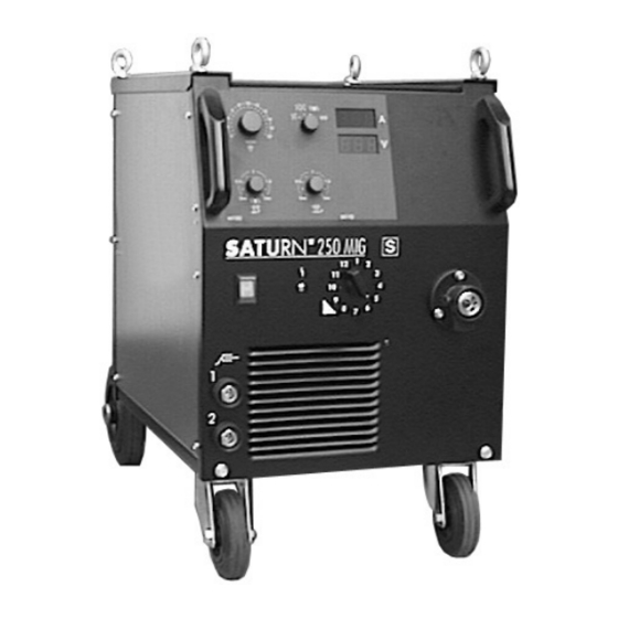
Description of the System components The Welding Power Source 4.2.1 SATURN 200 - 300 Welding Machine Series (Front and rearview) In the Unit polarity switching Fig. 4/1; Front View Fig. 4/2; Rear View... -
Page 19: Saturn 200 - 300 Welding Machine Series (Front- And Rearview)
Description of the System components 4.2.1 SATURN 200 - 300 Welding Machine Series (Front- and rearview) Transport handle Control "PROGRAM" M201 / M100 Main Switch, Machine On/Off LED for fault display for excess temperature and / or lack of coolant Welding Current Bush -, Work-piece connection Choke tapping CO (hard) -
Page 20: Controls
Description of the System components Controls 4.3.1 Control "PROGRAM" M201 Fig.: 4/3 Control "PROGRAM" M201... - Page 21 Description of the System components 4.3.1 Control "PROGRAM" M201 Rotary knob for the stepless setting of: • Correction of the wire-feed speed m/min • Wire-feed speed 1 - 20 m/min (Selector switch set to Manual position) Signal - Lamp: Recommended change of switch setting if welding power selection too high "Turn Step switch to the left"...
-
Page 22: Control M100
Description of the System components 4.3.2 Control M100 m/min 0sec 2sec 0sec 2sec Fig.: 4/4 Operating panel M100 Rotary knob "Wire feed speed" for stepless selection of the wire feed speed (1 - 20m/min) Rotary knob "Spot and Pause Time" for stepless selection of the welding times (0 - 2s) 0sec 2sec... -
Page 23: Volt-/ Ammeter Display
Description of the System components Volt - Ammeter Displays 4.4.1 M110: digital V/A- Meter with Hold- Function (Option for M100 / M201) Fig.: 4/6; Operating panel digital voltage and current display M110 Digital Welding Current Display Digital Welding Voltage Display The Remote Control (Option, only for use with the M201) Only remote controls which are described in this manual may be connected! Remote controls may only be plugged in or unplugged when the unit is switched off! -
Page 24: The Interfaces(Option, Only With The M201)
Description of the System components 4.5.2 Hand Remote Control on the Welding Torch (Option) The Interfaces (Option, only with the M201) 4.6.1 Automation Interface(Option, only for the M201) The welding power source is characterised by a very high standard of safety. This high safety standard is also retained when the machine is used with peripheral equipment for mechanised welding, if this peripheral equipment also meets the same criteria, especially with respect to insulation and power supply. -
Page 25: 5.1 Description M100 Control
Steuerungsbeschreibung M100 / M110 5.1 Description M100 Control Fig. 5/1: M100 Control 5.1.1 Setting the Working Point The M100 MIG/MAG control functions on the two-knob operating principle, i.e.: to determine his working point the operator must only enter the required Wire feed speed on the control and the Welding Voltage on the step switches corresponding to the material and the welding wire diameter. -
Page 26: Selection Of Operating Modes
Steuerungsbeschreibung M100 / M110 5.1.2 Selection of Operating Modes Operating mode The operating modes can be suited to the corresponding selection switch welding job 2- Stroke Setting e.g.: Tacking, short weld seams (latch on, latch off) 4- Stroke Setting e.g.: long weld seams Spot Welding Setting e.g.: Spot Welding Interval Setting... -
Page 27: Setting Further Welding Parameters
Steuerungsbeschreibung M100 / M110 Setting further welding parameters Operating elements for setting the following welding parameters are in the welding machine or the wire-feed unit (Fig. 5/2). Fig. 5/2 Setting possibilities in the welding machine or the wire-feed unit 5.3.1 Wire Burn-back Trimmer Setting Instructions:... -
Page 28: Creep Start
Steuerungsbeschreibung M100 / M110 5.3.4 Creep start Creep start The wire creep feed-rate is a percentage of the preset wire feed rate. As standard this is factory set to 50%. (e.g.: Wire-feed speed = 10m/min ≥ Creep speed = 5 m/min) Advantage: The welding wire does not hit the workpiece at full speed. -
Page 29: Sequence Of Functions - Operating Modes
Steuerungsbeschreibung M100 / M110 Sequence of functions - Operating modes 5.4.1 Sequence of functions MIG 2-Step 1st Stroke 2nd Stroke pressed Torch Trigger (not) pressed flowing (not) flowing Welding Power m/min wire- feed Wire- Wire- Gas- Creep- feed Burn- back Post- flow Time 1st Step Press and hold torch trigger... -
Page 30: Sequence Of Functions 2-Step
Steuerungsbeschreibung M100 / M110 5.4.2 Sequence of functions MIG 4-Step 1st Stroke 2nd Stroke 3rd Stroke 4th Stroke pressed Torch Trigger (not) pressed flowing (not) flowing Welding Power m/min wire- feed Wire- Wire- Gas- Creep- feed Burn- back Post- flow Time 1st and 2nd Strokes Press and release torch trigger •... -
Page 31: Sequence Of Functions Spot Welding
Steuerungsbeschreibung M100 / M110 5.4.3 Sequence of functions MIG Spot Welding Weld Time pressed Torch Trigger (not) pressed flowing (not) flowing Welding Power m/min wire- feed Wire- Wire- Burn- back Gas- Creep- feed Post- flow Time Start Spot Welding Press and hold torch trigger •... -
Page 32: Sequence Of Functions Interval
Steuerungsbeschreibung M100 / M110 5.4.4 Sequence of functions MIG Interval Weld Time Pause Time Weld Time Pause Time Weld Time pressed Torch Trigger (not) pressed flowing (not) flowing Welding Power m/min wire- feed Wire- Wire Wire Wire- Gas- Creep- feed Creep- feed Creep- feed Burn- back... - Page 33 Description of M201 control Description of MIG/MAG Welding jobs PROGRAM 1-20 m/min 1-20 m/min m/min manuell CrNi SG/CrNi SG/CrNi AlMg AlMg 80-90% Ar 80-90% 100% Ar 100% SG/CrNi SG/CrNi AlSi AlSi 90-100% Ar 90-100% 100% Ar 100% Al99 Al99 4sec 100% CO2 100% 100% Ar...
-
Page 34: Mig/Mag- Welding Jobs And Setting Of The Working Point
Description of M201 control 6.1.1 MIG/MAG- welding jobs and setting the working point (without option M210 / operating mode Programme, one-knob operation) Selection switch Selection switch for the various types of gas gas type Selection switch Selection switch for setting the: welding wire •... -
Page 35: (Without Option M210 / Operating Mode Manual, Two-Knob Operation)
Description of M201 control 6.1.2 MIG/MAG- welding jobs and setting the working point (operating mode manual, two knob operation) Two knob operation as with conventional MIG/MAG welding units is possible with the M201 control. Selection switch Switch selection to the "manual" two knob operating mode welding wire setting. -
Page 36: Signal Lamps For Error Messages
Description of M201 control Signal lamps for error messages These signal lamps show the user operating errors or faults in the welding torch or in the machine. 6.4.1 Error message “too much/ too little” welding power pre-selected If the welding power pre-selected on the step switch is too high or too low for the welding wire diameter, the type of material and the gas type chosen the corresponding warning lamp lights up. -
Page 37: Correcting The Wire Feed Speed
Description of M201 control Correcting the wire feed speed 6.5.1 Correcting the wire feed speed with the remote control (Option) Setting the correction of the wire feed speed (one knob operation) or the wire feed speed (Operating mode manual, two knob operation) can be carried out independently of the settings on the control. -
Page 38: Further Functions
Description of M201 control Further Functions Operating elements to adjust the following welding parameters can be found in the welding machine (Fig. 6/3), or, with the decentralised version, in the wire-feed unit. Fig. 6/3; Adjustment possibilities in the welding machine 6.7.1 Wire Burn-back Trimmer... -
Page 39: Creep Start
Description of M201 control 6.7.3 Feeding in the welding wire Button The welding wire can be threaded through the hose-pack arc-off wire without voltage and without gas flowing. threading 6.7.4 Creep start Fig. 6/3; Screen print M201 control The wire creep speed depends on the welding task (on the material, type of gas and wire diameter) and is determined by characteristic curves. -
Page 40: Gas Preflow
Description of M201 control 6.7.5 Gas preflow The gas pre-flow time is set automatically to the optimum value for the type of material and gas selected. 6.7.6 Ignition Management The arc striking process is monitored and optimised to suit the prevailing conditions. This leads to consistent, reproducible arc striking characteristics under the widest variety of applications. -
Page 41: Sequence Of Functions In Operating Modes
Description of M201 control Sequence of functions - Operating modes .8.1 Sequence of functions MIG 2-Step 1st Stroke 2nd Stroke pressed Torch Trigger (not) pressed flowing (not) flowing Welding Power m/min wire- feed Wire Wire- Gas- Pre- flow Time Creep- feed Burn- back Post- flow Time Fig. -
Page 42: Sequence Of Functions 2-Stroke
Description of M201 control 6.8.2 Sequence of functions MIG 4-Step 1st Stroke 2nd Stroke 3rd Stroke 4th Stroke pressed Torch Trigger (not) pressed flowing (not) flowing Welding Power m/min wire- feed Wire Wire- Gas- Pre- flow Time Creep- feed Burn- back Post- flow Time Fig. -
Page 43: Sequence Of Functions Spot Welding
Description of M201 control 6.8.3 Sequence of functions MIG Spot Welding Weld Time pressed Torch Trigger (not) pressed flowing (not) flowing Welding Power m/min wire- feed Wire Wire- Gas- Pre- flow Time Creep- feed Burn- back Post- flow Time Fig. 6/6; Sequence of functions MIG Spot Welding Start Spot Welding Press and hold torch trigger... - Page 44 Short Operating Manual SATURN M201 PROGRAM Setting the welding task (One-knob operation programme) entsprechend der Schweißaufgabe: Gas type Set type of gas Wire diameter/ Set switch to type of material with the Material type corresponding wire diameter Welding power in fine steps Setting the welding power in fine steps Setting the operating mode Operating mode selection switch...
-
Page 45: Commissioning
Commissioning Setting up the Welding Machine Pay attention to the safety instructions “ For your safety” on the first page! • Set up the machine so that there is enough room to adjust the operating elements. • Take care that the unit is installed in a stabile position and appropriately secured to prevent it rolling away. -
Page 46: Cooling The Welding Machine
Commissioning Cooling the Welding Machine To achieve the optimum duty cycle from the power components, pay attention to the following conditions: • Ensure that the workplace is adequately ventilated, • The air inlets and outlets of the machine must be unobstructed, •... -
Page 47: Connection Of Mig Push/Pull- Torch(Option)
Commissioning 8.4.3 Connection of the MIG Push/Pull- Torch (Option) Description of function, Push / Pull Torch: An essential prerequisite for high welding economy and weld seam quality is an unimpaired welding wire feed. This is particularly problematic with: • The use of long hose-packs, •... -
Page 48: Inching The Wire Electrode
Commissioning 8.5.2 Inching the wire electrode Fig. 5/2: Operating elements inside the welding machine and the WF case Fig. 5/3: Part view of the wire feed • Lay out the torch hose package in an extended position • Loosen the knurled nuts A2 on the wire feed and swivel them outwards at the sides. The clamping elements B2 with the counter-rollers swivel upwards automatically. -
Page 49: Workpiece Cable
Commissioning Workpiece Cable Remove paint, rust and dirt from the clamping or welding location with a wire brush! Fix the earthing clamp or tongs close to the weld location! Assembly aids, pipes, rails etc.. may not be used as a return lead unless theyare part of the job itself! A perfect current flow must be ensured on welding benches and jigs! Torch and hosepack and the workpiece cable should never be rolled up in a spiral! -
Page 50: Shielding Gas Supply
Commissioning Shielding Gas Supply 8.7.1 Fitting the gas connections Place the shielding gas cylinders in the their support and secure them with the chain against accidents! No impurities may be allowed to get into the shielding gas lines as these could cause blockages. Open the cylinder valve briefly before connecting the pressure regulatorto blow out any dirt present. -
Page 51: Maintenance And Care
Maintenance and Care These welding machines require very little maintenance. However, depending upon the amount of dust occurring, the unit should be cleaned as described below and visually checked at least every 4 - 6 months. In so doing, the unit must be reliably isolated from the mains power supply. PULL OUT THE MAINS PLUG! (Switching off or pulling out a fuse does not give adequate isolation protection) Remove both side walls. -
Page 52: Operating Faults, Causes And Cures
Operating Faults, Causes and Cures 11.1 Customer Checklist All machines are subjected to very strict production and final testing. If something should not function correctly despite this, please refer to the following table. If none of the suggested cures clears the problem then please contact an authorised agency. Problem Possible Cause What to do... - Page 53 Operating Faults, Causes and Cures Problem Possible Cause What to do The weld seam is Too little or too much gas Wire diameter x 10 is gas flow in porous l/min Gas cylinder is empty Replace the cylinder Unsuitable gas quality or Use a different gas inadequate purity Excessive protrusion of welding...
-
Page 55: Spare Parts List
Ersatzteilliste/Spare Parts List 12/1... - Page 56 Ersatzteilliste/Spare Parts List Abb. 12/1: Vorderseite/front view Abb. 12/2: Rückseite/rear view 12/2...
- Page 57 Ersatzteilliste/Spare Parts List Pos. Bezeichnung: Description SATURN Leiterplatte M100 PCB M100 040-000509-00000 Seitenwand links side panel left 094-002661-00007 Netzschalter Ein/Aus mains on/off switch 094-002680-00000 LED - Anzeige LED - display 094-002752-00000 Anschlußbuchse connection socket 074-000232-00000 Lenkrolle turning rollers 094-000181-00000 Seitenwand rechts side panel right 094-002660-00007 Eurozentralanschluß...
- Page 58 Ersatzteilliste/Spare Parts List Abb. 12/3: rechte Seite/right side Abb. 12/4 linke Seite/left side 12/4...
- Page 59 Ersatzteilliste/Spare Parts List Pos. Bezeichnung: Description SATURN Drehknopf switch knob 094-000997-00000 zu A3 Potentiometer potentiometer 044-001782-00000 Klebefolie Adhesive film 094-006024-00000 Antrieb Drahtvorschub Wire feed 094-002753-00000 (individual parts see (Einzelteile siehe Fig. 12/5) Abb. 12/5) Motor Drahtvorschub wire feed motor 094-004274-00000 C3/D3 Vorschub komplett 092-000909-00000 wire feed complete...
- Page 60 Ersatzteilliste/Spare Parts List Abb. 12/5 a: Explosionszeichnung Drahtvorschubeinheit 2-Rollenantrieb / exploded view wire feed 2-rolls drive Abb.12/5b: Ersatzrollen Aluminium / spare part rolls aluminium Abb.12/5c: Ersatzrollen Fülldraht / spare part rolls cored wire 12/6...
- Page 61 Ersatzteilliste/Spare Parts List Pos. Bezeichnung: Description 094-006283-00000 Zwei Rollen Basisstück Feed plate fiter with inlet/outlet holders Holder pressure device 094-006284-00000 Halter Andruckeinrichtung Innensechskantschraube Allen screw 094-006265-00000 Pressure device with scale 094-006285-00000 Andruckeinrichtung mit Skala Splint Andruckeinrichtung Locating pin pressure device 094-006286-00000 Axle shaft pressure arm 094-006287-00000...
- Page 62 Ersatzteilliste/Spare Parts List Abb. 12/6a Explosionszeichnung Drahtvorschubeinheit 4-Rollenantrieb / exploded view wire feed 4-rolls drive Abb. 12/6b Ersatzrollen Aluminium / spare part rolls aluminium Abb. 12/6c Ersatzrollen Fülldraht / spare part rolls cored wire 12/8...
- Page 63 Ersatzteilliste/Spare Parts List Pos. Bezeichnung: Description Vier Rollen Basisstück Four roll feed plate 094-006257-00000 Schraube M6x14 Screw M6x14 094-006258-00000 Andruckarm rechts Pressure arm right hand 094-006259-00000 Andruckarm links Pressure arm left hand 094-006260-00000 Achsenwelle mit gerändeltem Kopf Axle shaft with knurled head 094-006261-00000 Knurled fixing screw axle shaft 094-006262-00000...
- Page 64 Accessories 13.1 Work-piece cables Description Version Part. No.: Work-piece cable 35 mm , 4m, Clamp WK35QMM - 4M/Z 092-000008-00000 Work-piece cable 50 mm , 4m, Clamp WK50QMM - 4M/Z 092-000003-00000 13.2 General Description Version Part. No.: RM remote control wire feed correction, 5m 090-008063-00000 Pressure regulator with gauge 28-30l/min 094-000009-00000...
-
Page 65: Circuit Diagrams
Schaltpläne / Circuit diagrams SATURN 250-300 (M100) 14/1... - Page 66 Schaltpläne / Circuit diagrams SATURN 250-300 (M100/M110) 14/2...
- Page 67 Schaltpläne / Circuit diagrams SATURN 250-300 (M200) 14/3...
- Page 68 Schaltpläne / Circuit diagrams SATURN 250-300 (M200/M110) 14/4...
Need help?
Do you have a question about the SATURN MIG 200 and is the answer not in the manual?
Questions and answers