Cisco NCS 540 Hardware Installation Manual
Hide thumbs
Also See for NCS 540:
- Configuration manual (72 pages) ,
- Command reference manual (84 pages) ,
- Configuration manual (19 pages)
Table of Contents

Related Manuals for Cisco NCS 540


Summary of Contents for Cisco NCS 540
- Page 1 Cisco NCS 540 Router Hardware Installation Guide First Published: 2018-03-28 Americas Headquarters Cisco Systems, Inc. 170 West Tasman Drive San Jose, CA 95134-1706 http://www.cisco.com Tel: 408 526-4000 800 553-NETS (6387) Fax: 408 527-0883...
- Page 2 Any use of actual IP addresses or phone numbers in illustrative content is unintentional and coincidental. Cisco and the Cisco logo are trademarks or registered trademarks of Cisco and/or its affiliates in the U.S. and other countries. To view a list of Cisco trademarks, go to this URL: www.cisco.com trademarks.
-
Page 3: Table Of Contents
External Alarm Inputs Console USB Console Online Insertion and Removal Power Supply (N540-PWR400-A and N540-PWR400-D) Fan Assembly (N540-FAN) C H A P T E R 3 Prepare for Installation General Precautions Site Planning Checklist Cisco NCS 540 Router Hardware Installation Guide... - Page 4 Install a Bale Clasp SFP or SFP+ Module Remove a Bale Clasp SFP or SFP+ Module Install and Remove QSFP+/QSFP28 Transceiver Modules Overview Required Tools and Equipment Install the 100-Gigabit Transceiver Module Attach the Optical Network Cable Cisco NCS 540 Router Hardware Installation Guide...
- Page 5 Install the DC Power Supply Module Remove the AC Power Supply Module Install the AC Power Supply Module A P P E N D I X A LEDs Router LEDs Fan Assembly LEDs Power Supply LEDs Cisco NCS 540 Router Hardware Installation Guide...
- Page 6 Contents Cisco NCS 540 Router Hardware Installation Guide...
-
Page 7: Safety Warnings
To prevent the system from overheating, do not operate it in an area that exceeds the maximum recommended ambient temperature of 158°F (70°C). Statement 1047 Warning Mount the device on a rack that is permanently affixed to the building. Statement 1049 Cisco NCS 540 Router Hardware Installation Guide... -
Page 8: Safety Guidelines For Personal Safety And Equipment Protection
Be sure to observe the following safety precautions when you work on the chassis. Warning Class 1 laser product. Statement 1008 Warning Do not stare into the beam or view it directly with optical instruments. Statement 1011 Warning Invisible laser radiations present. Statement 1016 Cisco NCS 540 Router Hardware Installation Guide... -
Page 9: Safety With Electricity
Statement 1024 Warning This unit may have more than one power supply connection. All connections must be removed to de-energize the unit. Statement 1028 Cisco NCS 540 Router Hardware Installation Guide... - Page 10 • Never perform any action that creates a potential hazard to people or makes the equipment unsafe. • If an electrical accident occurs and you are uninjured: • Use caution to avoid injuring yourself. • Turn off power to the device. Cisco NCS 540 Router Hardware Installation Guide...
-
Page 11: Power Supply Considerations
• Protect the circuit by a dedicated two-pole circuit breaker. Ensure that the circuit breaker is sized according to the power supply input rating and local or national code requirements. • The circuit breaker is considered as the disconnect device and is easily accessible. Cisco NCS 540 Router Hardware Installation Guide... -
Page 12: Guidelines For Ac-Powered Systems
• When removing a component, use available ejector levers or captive installation screws, if any, to release the bus connectors from the backplane or midplane. Cisco NCS 540 Router Hardware Installation Guide... - Page 13 • Never attempt to remove the printed circuit board from the metal carrier. For the safety of your equipment, periodically check the resistance value of the antistatic wrist strap. Maintain the value between 1 and 10 Mohm. Cisco NCS 540 Router Hardware Installation Guide...
- Page 14 Safety Warnings Preventing ESD Damage Cisco NCS 540 Router Hardware Installation Guide...
-
Page 15: Cisco Ncs 540 Router Overview
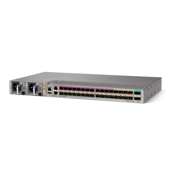
C H A P T E R Cisco NCS 540 Router Overview The Cisco NCS 540 1RU router complements Cisco’s offerings for IP RAN solutions for the GSM, UMTS, LTE, and CDMA. For more information on its features and benefits, see the... -
Page 16: Interface Naming
All ports are color coded in the chassis for ease of access; for example, the 10G SFP+ Ports are in pink, the 25G SFP+ Ports are in yellow, and the 100G QSFP28 Ports are in green. Interface Naming The following table shows the interface naming of the Cisco N540-24Z8Q2C-M ports: Table 1: Port Numbering 1G/10G Dual rate ports (SFP+) -
Page 17: Network Timing Interfaces
• Normally Open—indicates that no current flows through the alarm circuit and the alarm is generated when the current is flowing. Each alarm input can be provisioned as critical, major, or minor. Console The RS232 console port provides transmission (Tx), reception (Rx), and ground (Gnd). Cisco NCS 540 Router Hardware Installation Guide... -
Page 18: Usb Console
Power Supply (N540-PWR400-A and N540-PWR400-D) The Cisco NCS 540 router supports two AC or DC power supplies, which power the router. The second power supply ensures redundancy in the system. Both power supplies support hot swapping capabilities. -
Page 19: Prepare For Installation
C H A P T E R Prepare for Installation Before you install the Cisco NCS 540, you must prepare your site for the installation. Preparing your site involves these tasks: • General Precautions, on page 13 • Site Planning Checklist, on page 14 •... -
Page 20: Site Planning Checklist
The chassis ground must be attached to a central office or other interior ground system. Caution This product requires short-circuit (overcurrent) protection to be provided as part of the building installation. Install only in accordance with national and local wiring regulations. Cisco NCS 540 Router Hardware Installation Guide... -
Page 21: Electrical Circuit Requirements
Before you install the chassis, have on hand all additional external equipment and cables. For information about ordering, contact a Cisco customer service representative. The extent of your network and the distances between the network interface connections depend, in part, on the following factors: •... -
Page 22: Interference Considerations
• Ethernet hub, switch, or PC with a network interface card for connecting to the Ethernet ports • Console terminal that is configured for 9600 baud, 8 data bits, no parity, no flow control, and 1 stop bit. • Console cable for connecting to the console port Cisco NCS 540 Router Hardware Installation Guide... -
Page 23: Prepare Your Location
Prepare Your Location This section illustrates how the building that houses the chassis must be properly grounded to the earth ground. Figure 2: Building with Rack Room Connected to Earth Ground Cisco NCS 540 Router Hardware Installation Guide... -
Page 24: Prepare Yourself
Step 1 Place the rack where you plan to install the chassis. Ensure that the rack is grounded to earth. Step 2 Secure the rack to the floor. Cisco NCS 540 Router Hardware Installation Guide... -
Page 25: Unpack The Cisco Ncs 540 Router
Be sure to save the packaging in case you need to return any of the components products. Note These images are for only representation purposes. The chassis' actual appearance and size would vary. Cisco NCS 540 Router Hardware Installation Guide... - Page 26 Unpack the Cisco NCS 540 Router Figure 4: Unpacking the Device Regular Slotted Container Foam end caps (shipping box) Front corrugated cap Front end of the product Back end of the product Accessory tray Cisco NCS 540 Router Hardware Installation Guide...
-
Page 27: Install The Device
Before you begin this task, ensure that you have read and understood the safety warnings in the Standard Warning Statements section of the Safety Warnings handout topic. Installing the Cisco NCS 540 involves these tasks: • Rack-Mount, on page 21 • Ground the Device, on page 23 •... - Page 28 Use four M4 screws to attach the bracket to the chassis. d) Repeat Steps 1b and 1c with the other rack-mount bracket on the other side of the router. Figure 5: Rack-mount brackets on Cisco NCS 540 Step 3 Install the router onto the 2-post rack as follows: a) Lift and position the router into position between the two rack posts.
-
Page 29: Ground The Device
This section describes how to ground the device. The grounding lug location is on the back panel of the device. Step 1 Verify that the ground cable is connected to the top of the rack and according to local site practice. Figure 6: Cisco NCS 540 Ground Lug Grounding lug M4 x 12 mm pan-head... -
Page 30: Install The Ac Power Cables
Perform the following procedure to activate an AC power supply: Step 1 Plug the power cord into the power supply. Step 2 Connect the other end of the power cord to an AC-input power source. Cisco NCS 540 Router Hardware Installation Guide... -
Page 31: Install The Dc Power Cables
Insert the DC-input power source wires into the terminal block plug. Step 3 Attach the DC supply wires using the designated screws. Step 4 Use a ratcheting torque screwdriver to torque the terminal block plug captive screw. See the following figure. Cisco NCS 540 Router Hardware Installation Guide... -
Page 32: Activate A Dc Power Supply Module
Depending on the chassis and installed line cards, you can use Quad Small Form-Factor Pluggable Plus (QSFP+), QSFP28, SFP, SFP+, and RJ-45 connectors to connect the ports on the line cards to other network devices. Cisco NCS 540 Router Hardware Installation Guide... -
Page 33: Connect To The Console Port
Install the Device Connect to the Console Port To prevent damage to the fiber-optic cables, Cisco recommends that you keep the transceivers disconnected from their fiber-optic cables when installing the transceiver in the line card. Before removing a transceiver from the router, remove the cable from the transceiver. - Page 34 Attach the other end of the cable to the console port. Following table represents the RJ-45 cable pin-out information. Table 4: RJ-45 Straight-through Cable Pin-outs RJ-45 Pin Signal — — Ground (GND) — Cisco NCS 540 Router Hardware Installation Guide...
-
Page 35: Connect To The Management Ethernet Port
You must complete initial router configuration. Step 1 Plug the cable directly into the RJ-45 receptacle. Step 2 Connect the network end of your RJ-45 cable to a switch, hub, repeater, or other external equipment. Cisco NCS 540 Router Hardware Installation Guide... -
Page 36: Install And Remove Transceiver Modules
Disconnect all cables before removing or installing an SFP or SFP+ module. Removing and inserting a module can shorten its useful life, so you should not remove and insert modules any more than is absolutely necessary. Cisco NCS 540 Router Hardware Installation Guide... -
Page 37: Bale Clasp Sfp Or Sfp+ Module
This click indicates that the module is correctly seated and secured in the receptacle. Verify that the SFP modules are completely seated and secured in their assigned receptacles on the line card by firmly pushing on each SFP module. Cisco NCS 540 Router Hardware Installation Guide... -
Page 38: Remove A Bale Clasp Sfp Or Sfp+ Module
Grasp the SFP module between your thumb and index finger and carefully remove it from the port, as shown in the figure below. Note This action must be performed during your first instance. After all the ports are populated, this may not be possible. Cisco NCS 540 Router Hardware Installation Guide... - Page 39 Place the removed SFP module on an antistatic mat, or immediately place it in a static shielding bag if you plan to return it to the factory. Step 6 Protect your line card by inserting a clean SFP module cage covers into the optical module cage when there is no SFP module installed. Cisco NCS 540 Router Hardware Installation Guide...
-
Page 40: Install And Remove Qsfp+/Qsfp28 Transceiver Modules
Maintain Transceivers and Optical Cables. Install the 100-Gigabit Transceiver Module The QSFP+ or QSFP28 transceiver module can have either a bail-clasp latch or a pull-tab latch. Installation procedures for both types of latches are provided. Cisco NCS 540 Router Hardware Installation Guide... - Page 41 Press firmly on the front of the QSFP+ or QSFP28 transceiver module with your thumb to fully seat the transceiver in the module’s transceiver socket (see the below figure). If the latch is not fully engaged, you might accidentally disconnect the QSFP+ or QSFP28 transceiver module. Caution Cisco NCS 540 Router Hardware Installation Guide...
-
Page 42: Attach The Optical Network Cable
• Inspect and clean the MPO connector end faces just before you make any connections. • Grasp the MPO connector only by the housing to plug or unplug a fiber-optic cable. Note 40-Gigabit QSFP+ or QSFP28 transceiver modules are keyed to prevent incorrect insertion. Cisco NCS 540 Router Hardware Installation Guide... -
Page 43: Remove The 100-Gigabit Qsfp28 Transceiver Module
For QSFP+ or QSFP28 transceivers equipped with a pull tab latch (see the below figure, bottom view): a) Immediately install the dust plug into the transceiver’s optical bore. b) Grasp the tab and gently pull to release the transceiver from the socket. Cisco NCS 540 Router Hardware Installation Guide... -
Page 44: Connect Interface Ports
Disconnect Optical Ports from the Network When you need to remove fiber-optic transceivers, you must first remove the fiber-optic cables from the transceiver before you remove the transceiver from the port. Cisco NCS 540 Router Hardware Installation Guide... -
Page 45: Maintain Transceivers And Optical Cables
• Inspect routinely for dust and damage. Clean and then inspect fiber ends under a microscope to determine whether any damage has occurred. Cisco NCS 540 Router Hardware Installation Guide... - Page 46 Install the Device Maintain Transceivers and Optical Cables Cisco NCS 540 Router Hardware Installation Guide...
-
Page 47: Configure The Device
Before you begin this task, ensure that you have read and understood the safety warnings in the Safety with Electricity section of the Safety Warnings handout topic. Configuring the Cisco NCS 540 involves these tasks: • Create the Initial Router Configuration, on page 41 • Verify Device Installation, on page 43 Create the Initial Router Configuration You must assign an IP address to the router management interface so that you can then connect the router to the network. - Page 48 The software asks if you need to edit the configuration. Enter no to not edit the configuration. Step 8 The software asks if you need to save the configuration. Enter yes to save the configuration. Cisco NCS 540 Router Hardware Installation Guide...
-
Page 49: Verify Device Installation
Configure the Device Verify Device Installation Verify Device Installation After installing the Cisco NCS 540 Router, you can use the show commands to verify the installation and configuration. If any issue is detected, take corrective action before making further configurations. Step 1... - Page 50 Displays the voltage for the entire router. Step 7 show environment current Example: #show environment current Displays the current environment status. Step 8 show environment fan Example: #show environment fan Displays the status of the fan trays. Cisco NCS 540 Router Hardware Installation Guide...
-
Page 51: Replace Fan Module And Power Supply
Before you begin this task, ensure that you have read and understood the safety warnings in the Safety with Electricity section of the Safety Warnings handout topic. Replacing the Cisco NCS 540 involves these tasks: • Replace Fan Module, on page 45 • Replace Power Supply, on page 46 Replace Fan Module... -
Page 52: Replace Power Supply
You can use standard right angle power cords with the AC power supply. The power supply includes a power cord retainer. No ON/OFF switch is provided. You can install dual power supplies for redundancy. Cisco NCS 540 Router Hardware Installation Guide... -
Page 53: Remove The Dc Power Supply Module
The grounding architecture of this product is DC-Isolated (DC-I) for DC-powered products. DC-powered products have a nominal operating DC voltage of 48 VDC. Perform the following procedure to install the power supply module: Cisco NCS 540 Router Hardware Installation Guide... -
Page 54: Remove The Ac Power Supply Module
Only trained and qualified personnel should be allowed to install, replace, or service this equipment. Statement 1030 Warning Installation of the equipment must comply with local and national electrical codes. Statement 1074 Follow these steps to remove and replace the AC power supply: Cisco NCS 540 Router Hardware Installation Guide... -
Page 55: Install The Ac Power Supply Module
Slide the AC power supply cord inside the tie of the tie-and-holder and tighten the tie around the power supply cord. Step 5 Plug the power supply cord into the AC power supply. Cisco NCS 540 Router Hardware Installation Guide... - Page 56 Replace Fan Module and Power Supply Install the AC Power Supply Module Cisco NCS 540 Router Hardware Installation Guide...
-
Page 57: Leds
Power Supply LEDs, on page 53 Router LEDs All the data port LEDs in the Cisco NCS 540 Router is at the front panel. There are 5 LEDs that reflect the different statuses of the system. Table 5: Router LED Descriptions... -
Page 58: Fan Assembly Leds
Learning state–normal. Self-survey is not completed. Fan Assembly LEDs Cisco NCS 540 has 4 fans at the back panel. There is an LED on each fan assembly and they reflect the different status of the fans. Cisco NCS 540 Router Hardware Installation Guide... -
Page 59: Power Supply Leds
• Power supply is installed in the chassis but has been disconnected from the power source Amber Power supply failure—possibly one of the following conditions: • Over voltage • Over current • Over temperature • Power supply fan failure Cisco NCS 540 Router Hardware Installation Guide... - Page 60 LEDs Power Supply LEDs Cisco NCS 540 Router Hardware Installation Guide...
Need help?
Do you have a question about the NCS 540 and is the answer not in the manual?
Questions and answers