Table of Contents
Advertisement
Quick Links
Advertisement
Table of Contents

Related Manuals for Cisco NCS 500 Series


Summary of Contents for Cisco NCS 500 Series
- Page 1 Cisco NCS 540 Router Hardware Installation Guide First Published: 2018-03-28 Last Modified: 2021-07-30 Americas Headquarters Cisco Systems, Inc. 170 West Tasman Drive San Jose, CA 95134-1706 http://www.cisco.com Tel: 408 526-4000 800 553-NETS (6387) Fax: 408 527-0883...
- Page 2 Cisco and the Cisco logo are trademarks or registered trademarks of Cisco and/or its affiliates in the U.S. and other countries. To view a list of Cisco trademarks, go to this URL: https://www.cisco.com/c/en/us/about/legal/trademarks.html.
-
Page 3: Table Of Contents
Cisco NCS 540 Router Overview Network Interfaces Specification Interface Naming Port Speed on 25G Ports Network Timing Interfaces GNSS GNSS Module RF Input Requirements External Alarm Inputs Console USB Console Online Insertion and Removal Supported Transceiver Modules Cisco NCS 540 Router Hardware Installation Guide... - Page 4 Install the AC Power Cables Activate an AC Power Supply Module Install the DC Power Cables Activate a DC Power Supply Module Port Connection Guidelines Connect to the Console Port Connect to the Management Ethernet Port Cisco NCS 540 Router Hardware Installation Guide...
- Page 5 Replace Fan Module and Power Supply Replace Fan Module Replace Power Supply Remove the DC Power Supply Module Install the DC Power Supply Module Remove the AC Power Supply Module Install the AC Power Supply Module Cisco NCS 540 Router Hardware Installation Guide...
- Page 6 Transceiver and Cable Specifications RJ-45 Connectors GPS Port Pinouts Time-of-Day Port Pinouts BITS Interface Management and PTP Ethernet Port Pinouts USB Port Pinouts Alarm Port Pinouts Console Port Pinouts AC Power Cord Specifications Cisco NCS 540 Router Hardware Installation Guide...
-
Page 7: Safety Warnings
Material Safety Law prohibits the use of UL-certified cables (that have the "UL" or "CSA" shown on the cord), not regulated with the subject law by showing "PSE" on the cord, for any other electrical devices than products designated by Cisco. Cisco NCS 540 Router Hardware Installation Guide... - Page 8 • If the rack is provided with stabilizing devices, install the stabilizers before mounting or servicing the unit in the rack. Warning Statement 1018 Supply Circuit To reduce risk of electric shock and fire, take care when connecting units to the supply circuit so that wiring is not overloaded. Cisco NCS 540 Router Hardware Installation Guide...
- Page 9 To reduce the risk of fire or bodily injury, do not operate the unit in an area that exceeds the maximum recommended ambient temperature of: –40 to 158°F (–40 to 65°C) Warning Statement 9001 Product Disposal Ultimate disposal of this product should be handled according to all national laws and regulations. Cisco NCS 540 Router Hardware Installation Guide...
-
Page 10: Safety Guidelines For Personal Safety And Equipment Protection
• When working under conditions that may be hazardous to your eyes, wear safety glasses. Safety Precautions for Module Installation and Removal Be sure to observe the following safety precautions when you work on the chassis. Cisco NCS 540 Router Hardware Installation Guide... - Page 11 Warning Statement 1090 Installation by Skilled Person Only a skilled person should be allowed to install, replace, or service this equipment. See statement 1089 for the definition of a skilled person. Cisco NCS 540 Router Hardware Installation Guide...
-
Page 12: Safety With Electricity
This equipment must be grounded. To reduce the risk of electric shock, never defeat the ground conductor or operate the equipment in the absence of a suitably installed ground conductor. Contact the appropriate electrical inspection authority or an electrician if you are uncertain that suitable grounding is available. Cisco NCS 540 Router Hardware Installation Guide... - Page 13 Statement 1088 Avoid Servicing Outdoor Connections During an Electrical Storm Avoid using or servicing any equipment that has outdoor connections during an electrical storm. There may be a risk of electric shock from lightning. Cisco NCS 540 Router Hardware Installation Guide...
-
Page 14: Power Supply Considerations
• Never install telephone wiring during a lightning storm. Power Supply Considerations Check the power at your site to ensure that you are receiving clean power (free of spikes and noise). If necessary, install a power conditioner. Cisco NCS 540 Router Hardware Installation Guide... -
Page 15: Power Connection Guidelines
• The AC power receptacles that are used to plug in the chassis must be the grounding type. The grounding conductors that connect to the receptacles must connect to protective earth ground at the service equipment. Prevent Power Loss Use the following guidelines to prevent power loss to the device: Cisco NCS 540 Router Hardware Installation Guide... -
Page 16: Preventing Esd Damage
• Never attempt to remove the printed circuit board from the metal carrier. For the safety of your equipment, periodically check the resistance value of the antistatic wrist strap. Maintain the value between 1 and 10 Mohm. Cisco NCS 540 Router Hardware Installation Guide... -
Page 17: Cisco Ncs 540 Router Overview
Note The Cisco N540-24Z8Q2C-SYS, N540X-ACC-SYS, N540-ACC-SYS, N540-28Z4C-SYS-A/D, N540-12Z20G-SYS-A/D, N540X-12Z16G-SYS-A/D and N540X-16Z4G8Q2C-A/D are collectively referred to as the Cisco NCS 540 Router in this document. Any differences between the routers are specifically called out. Cisco NCS 540 Router Hardware Installation Guide... -
Page 18: Network Interfaces
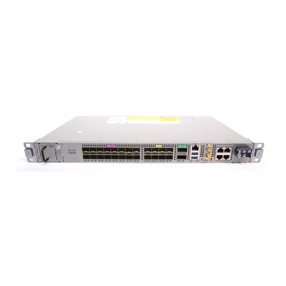
Online Insertion and Removal, on page 20 • Supported Transceiver Modules, on page 20 Network Interfaces The Cisco NCS 540 1RU Router has the following hardware features: • 24 x 10G SFP+ Ports • Support DWDM & ZR Optics • 8 x 25G SFP+ Ports •... - Page 19 Cisco NCS 540 Router Overview Network Interfaces Figure 3: Cisco N540-28Z4C-SYS-D The Cisco N540-12Z20G-SYS-A/D 1RU Router has the following hardware features: • 20 x 1G SFP+ Ports • 12 x 1G/10G SFP+ Ports Figure 4: Cisco N540-12Z20G-SYS-A Figure 5: Cisco N540-12Z20G-SYS-D The Cisco N540X-12Z16G-SYS-A/D 1RU Router has the following hardware features: •...
-
Page 20: Specification
Specification Figure 8: Cisco N540X-16Z4G8Q2C-A Figure 9: Cisco N540X-16Z4G8Q2C-D The Cisco N540X-16Z8Q2C-D router has the copper ports (0 to 3) removed. The router has the following hardware features: • 16 x 1G/10G SFP+ Ports • 8 x 10G/25G SFP+ Ports •... - Page 21 1/0 - 1 100GE 1/0 - 1 *4x10GE or 4x25GE option The following table shows the interface naming of the Cisco N540-28Z4C-SYS-A/D, N540-12Z20G-SYS-A/D, N540X-12Z16G-SYS-A/D, N540X-16Z4G8Q2C-A/D, and N540X-16Z8Q2C-D variants: Table 4: Port Numbering of Cisco N540-28Z4C-SYS-A/D 1G/10G Dual rate ports 100G ports...
- Page 22 Cisco NCS 540 Router Overview Interface Naming Table 5: Port Numbering of Cisco N540X-12Z16G-SYS-A/D 1G Copper 1G ports 10G ports ports (SFP) (SFP+) 0/16 0/15 0/27 • GigE — 0/0/0/4 - 0/0/0/15 • TenGigE — 0/0/0/16 - 0/0/0/27 Table 6: Port Numbering of Cisco N540-12Z20G-SYS-A/D...
-
Page 23: Port Speed On 25G Ports
Cisco NCS 540 Router Overview Port Speed on 25G Ports Table 8: Port Numbering of Cisco N540X-16Z8Q2C-D 1G/10G Dual rate ports 1G/10G/25G Dual rate ports (SFP28) 100G ports (SFP+) (QSFP28) 0/20 0/28 0/19 0/27 0/29 • GigE — 0/0/0/4 - 0/0/0/27 •... -
Page 24: Network Timing Interfaces
• For optimal performance, the GNSS module requires an active GPS/GNSS antenna with built-in Low-Noise Amplifier (LNA). The antenna LNA amplifies the received satellite signals for two purposes: • Compensation of losses on the cable Cisco NCS 540 Router Hardware Installation Guide... -
Page 25: External Alarm Inputs
The router supports four dry contact alarm inputs through an RJ-45 jack at the rear panel. • Normally Open—indicates that no current flows through the alarm circuit and the alarm is generated when the current is flowing. Each alarm input can be provisioned as critical, major, or minor. Cisco NCS 540 Router Hardware Installation Guide... -
Page 26: Console
A single USB 2.0 Type-A receptacle on the front panel of the router provides console access to ROMMON, Cisco IOS-XR and diagnostics. While it uses the Type-A connector, it operates as a USB peripheral only for connection to an external host computer. This interface requires the use of a Type-A to Type-A connector instead of a standard USB cable. -
Page 27: Prepare For Installation
C H A P T E R Prepare for Installation Before you install the Cisco NCS 540, you must prepare your site for the installation. Preparing your site involves these tasks: • General Precautions, on page 21 • Site Planning Checklist, on page 22 •... -
Page 28: Site Planning Checklist
Environmental Requirements Note The outside plant installation is not supported on Cisco N540-28Z4C-SYS-A/D, and N540-12Z20G-SYS-A/D routers. For outside plant installation (cell site cabinet, hut, and so on), you must protect the router against airborne contaminants, dust, moisture, insects, pests, corrosive gases, polluted air, or other reactive elements. Sealed equipment chamber with air-conditioning or a heat exchanger is recommended for OSP deployments. - Page 29 Prepare for Installation Airflow Guidelines • Rear clearance—2 inches (5.08 centimeters) Figure 11: Top View of Clearance Figure 12: Side View of Clearance Cisco NCS 540 Router Hardware Installation Guide...
- Page 30 An enclosed rack must have louvered sides and a fan to provide cooling air. The equipment generates heat near the bottom of the rack, which can be drawn upward into the intake ports of the equipment above. Cisco NCS 540 Router Hardware Installation Guide...
-
Page 31: Site Power Guidelines
This product requires an external surge protection device for both AC and DC power feeds to the equipment. For a DC power feed, the surge protective device (SPD) must handle common mode and differential mode surge as per the local standards. Cisco NCS 540 Router Hardware Installation Guide... -
Page 32: Electrical Circuit Requirements
The chassis supports both DC source or an AC source. Ensure that equipment grounding is present and observe power-strip ratings. Make sure that the total ampere rating of all the products plugged into the power strip does not exceed 80% of the rating. Cisco NCS 540 Router Hardware Installation Guide... -
Page 33: Site Cabling Guidelines
Before you install the router, have all the additional external equipment and cables on hand. For information about ordering, contact a Cisco customer service representative. The extent of your network and the distances between the network interface connections depend, in part, on the following factors: •... -
Page 34: Prepare Your Location
• Ratcheting torque screwdriver with a Phillips head that exerts up to 15 inch-pounds (1.69 newton meters) of torque for attaching the ground wire to the device Prepare Your Location This section illustrates how the building that houses the chassis must be properly grounded to the earth ground. Cisco NCS 540 Router Hardware Installation Guide... -
Page 35: Prepare Yourself
The figures show how to wear the ESD strap around the wrist and how to connect the other end of the strap to the ground. ESD wrist straps are the primary means of controlling static charge on personnel. Note: These images are for only representation purposes. The chassis' actual appearance and size would vary. Cisco NCS 540 Router Hardware Installation Guide... -
Page 36: Prepare Rack For Router Installation
Equipment intended for installation in outside plant (OSP) areas must have sealed cabinets with heat exchanger that meet the NEMA -4 or IP66 protection and low average yearly levels of concentration of contaminants inside the cabinet. Cisco NCS 540 Router Hardware Installation Guide... -
Page 37: Unpack The Cisco Ncs 540 Router
Before you begin Ensure that there is sufficient room around the chassis pallet for unpacking. Step 1 Remove the accessory tray and the packing material. Step 2 Carefully set the packing material aside. Cisco NCS 540 Router Hardware Installation Guide... - Page 38 These images are for only representation purposes. The chassis' actual appearance and size would vary. Note Figure 16: Unpacking the Device Regular Slotted Container (shipping box) Foam end caps Front corrugated cap Front end of the product Back end of the product Accessory tray Cisco NCS 540 Router Hardware Installation Guide...
- Page 39 Note Most Cisco documentation is available online. The chassis Pointer Card that is shipped with your Cisco NCS 500 Series Services Routers contains links and information to other online documentation. Note If the product is not in use, store the device in the initial packaged condition or in an ESD PE sealed bag with silica gel.
- Page 40 Prepare for Installation Unpack the Cisco NCS 540 Router Category Model ETSI rack mount brackets N540-RCKMT-ETSI Cisco NCS 540 Router Hardware Installation Guide...
-
Page 41: Install The Device
N540-28Z4C-SYS-A/D, N540-12Z20G-SYS-A/D, N540X-12Z16G-SYS-A/D and N540X-16Z4G8Q2C-A/D variants remains similar and any differences between the routers are specifically called out. The illustrations are for reference purpose only and may vary based on your Cisco NCS 540 variant. • Rack Compatibility, on page 35 •... -
Page 42: Rack Types
17.75 inches (45 18.31 inches (46.5 19 inches (48.2 centimeters) centimeters) centimeters) centimeters) 2 Post 4 Post 23 inches (58.4 21.75 inches (55.24 22.31 inches (56.6 23 inches (58.4 centimeters) centimeters) centimeters) centimeters) 2 Post Cisco NCS 540 Router Hardware Installation Guide... - Page 43 Install the Device Rack Types Figure 18: Four Post Rack Type Cisco NCS 540 Router Hardware Installation Guide...
-
Page 44: Set Up Device On Rack Or Wall
Figure 19: Two Post Rack Type Set up Device on Rack or Wall You can choose to either set up the Cisco NCS 540 on a rack or wall mount it. Note Wall mount is supported only on Cisco N540-24Z8Q2C-SYS, N540X-ACC-SYS, N540-ACC-SYS, N540-28Z4C-SYS-A/D, and N540-12Z20G-SYS-A/D routers. - Page 45 Install the Device Rack-Mount Table 14: Cisco NCS 540 Router Rack-Mount Kit Quantity Part Description Rack-mount brackets M4 x 0.7 x 6-mm Phillips flat-head screws M3 x 0.5 x 4-mm Phillips countersink screws Top cover or the NEBs kit is an optional accessory to improve the airflow, hence it may not be a part of your standard package.
- Page 46 Install the Device Rack-Mount Figure 21: Installing Cable Management and 19 inch Rack-Mount Brackets in the Front Figure 22: Installing Cable Management and 19 inch Rack-Mount Brackets in the Front (N540-28Z4C-SYS-D) Cisco NCS 540 Router Hardware Installation Guide...
- Page 47 Install the Device Rack-Mount Figure 23: Installing Cable Management and 19 inch Rack-Mount Brackets in the Middle Figure 24: Installing Cable Management and 19 inch Rack-Mount Brackets in the Middle (N540-28Z4C-SYS-D) Cisco NCS 540 Router Hardware Installation Guide...
- Page 48 Install the Device Rack-Mount Figure 25: Installing Cable Management and 19 inch Rack-Mount Brackets in the Rear (N540-28Z4C-SYS-D) Figure 26: Installing Cable Management and 23 inch Rack-Mount Brackets in the Front Cisco NCS 540 Router Hardware Installation Guide...
- Page 49 Install the Device Rack-Mount Figure 27: Installing Cable Management and 23 inch Rack-Mount Brackets in the Front (N540-28Z4C-SYS-D) Figure 28: Installing Cable Management and 23 inch Rack-Mount Brackets in the Middle Cisco NCS 540 Router Hardware Installation Guide...
- Page 50 Install the router onto the 2-post rack as follows: a) Lift and position the router into position between the two rack posts. b) Move the router until the rack-mount brackets come in contact with the two rack posts. Cisco NCS 540 Router Hardware Installation Guide...
-
Page 51: Wall Mount
Wall Mount Install the wall mounting brackets and cable guides on to the chassis before you mount the chassis on the wall. Note The wall mount is supported only on Cisco N540-24Z8Q2C-SYS, N540X-ACC-SYS, N540-ACC-SYS, N540-28Z4C-SYS-A/D, and N540-12Z20G-SYS-A/D routers. Install Wall Brackets The device is shipped with wall mounting brackets that are to be secured on the sides of the device. - Page 52 Install the Device Install Wall Brackets Figure 31: Install Wall Mount Brackets (N540-28Z4C-SYS-D) Cisco NCS 540 Router Hardware Installation Guide...
-
Page 53: Wall Mount The Device
While you mount the device, always ensure that the power supplies are at the top position. For the support of the device and cables, ensure that the device is attached securely to wall studs or to a firmly attached plywood mounting backboard. Cisco NCS 540 Router Hardware Installation Guide... - Page 54 Install the Device Wall Mount the Device Figure 32: Wall Mount the Device (N540-28Z4C-SYS-D) Cisco NCS 540 Router Hardware Installation Guide...
- Page 55 Install the Device Wall Mount the Device Cisco NCS 540 Router Hardware Installation Guide...
-
Page 56: Ground The Device
Prepare the other end of the grounding cable and connect it to an appropriate grounding point in your site to ensure adequate earth ground. Install the AC Power Cables To install the AC power cables in the power supply slots: Cisco NCS 540 Router Hardware Installation Guide... -
Page 57: Activate An Ac Power Supply Module
Insert the power supply cord into the tie [1,3] and tighten the tie around the power supply cord as shown in [2,4] in the figure below. Figure 34: Attach the AC Power Tie-and-Clip Cord These images are for only representation purposes. Certain variants of Cisco NCS 540 do not include a tie Note for the power supply cord. -
Page 58: Install The Dc Power Cables
When installing DC power supply, use 12AWG, 90°C temperature rated cable. The recommended cable length is 3 meters maximum from source. Up to 5 meters use 10AWG, and up to 3 meters use 12AWG, 90°C temperature rated cable and for other length contact Cisco. Note For N540X-16Z4G8Q2C-A/D and N540X-16Z8Q2C-D, when installing DC power supply, use 14-16AWG, 90°C temperature rated cable. -
Page 59: Activate A Dc Power Supply Module
Figure 36: Attach the DC Power Supply Wires Note These images are for only representation purposes. Certain variants of Cisco NCS 540 may vary. Activate a DC Power Supply Module Perform the following procedure to activate a DC power supply:... -
Page 60: Port Connection Guidelines
IP address for the router. You also can use the console to perform the following functions (each of which can be performed through the management interface after you make that connection): Cisco NCS 540 Router Hardware Installation Guide... - Page 61 • Download software updates. The system console port is an RJ-45 receptacle for connecting a data terminal to perform the initial configuration of Cisco NCS 540 fixed-port chassis. The console cable is shipped with the hardware. Note Only RJ45 to DB-9 adapter cable is provided in the package.
- Page 62 • The necessary cabling for the console, management, and network connections must be available. • An RJ-45 rollover cable and DB9F/RJ-45 adapter are provided in the router accessory kit. • Network cabling should already be routed to the location of the installed router. Cisco NCS 540 Router Hardware Installation Guide...
-
Page 63: Connect To The Management Ethernet Port
To prevent an IP address conflict, do not connect the management Ethernet port until the initial configuration is complete. To connect cables to the system management port, attach Category 5 cables directly to the RJ-45 receptacle on the management Ethernet port. Cisco NCS 540 Router Hardware Installation Guide... -
Page 64: Connecting Timing Cables
When installing the cables to the RSPs, we recommend that you leave a service loop of extra cable to enable fan tray removal. The following sections describe how to connect timing cables to the router: Cisco NCS 540 Router Hardware Installation Guide... -
Page 65: Connecting A Cable To The Bits Interface
Connect one end of a straight-through Ethernet cable to the GPS unit. Step 2 Connect the other end of the straight-through Ethernet cable to the ToD or 1-PPS port on the RSP of the router. Cisco NCS 540 Router Hardware Installation Guide... -
Page 66: Connecting A Cable To The Gnss Antenna Interface
1. Connect one end of a shielded coaxial cable to the GNSS RF IN port. 2. SMA Matting cable assembly Torque should be maintained within 3 in-lb. For Cisco N540-24Z8Q2C-SYS, Cisco N540X-ACC-SYS, and Cisco N540-ACC-SYS nut and washer may be removed when you use a slightly longer mating SMA connector to ensure contact with the connector. -
Page 67: Bale Clasp Sfp Or Sfp+ Module
SFP or SFP+ module. Bale Clasp SFP or SFP+ Module The bale clasp SFP or SFP+ module has a clasp that you use to remove or install the module (see the figure below). Cisco NCS 540 Router Hardware Installation Guide... -
Page 68: Install A Bale Clasp Sfp Or Sfp+ Module
Open the bale clasp on the SFP module with your index finger, as shown in the figure below. If the bale clasp is obstructed and you cannot use your index finger to open it, use a small flat-blade screwdriver or other long, narrow instrument to open the bale clasp. Cisco NCS 540 Router Hardware Installation Guide... - Page 69 Figure 42: Removing a Bale Clasp SFP or SFP+ Module Step 5 Place the removed SFP module on an antistatic mat, or immediately place it in a static shielding bag if you plan to return it to the factory. Cisco NCS 540 Router Hardware Installation Guide...
-
Page 70: Install And Remove Qsfp Transceiver Modules
Figure 43: 400-Gigabit QSFP-DD Transceiver Module Pull-tab QSFP-DD transceiver body Electrical connection to the module circuitry Warning Statement 1079 Hot Surface This icon is a hot surface warning. Use precaution when working near the hot surface. Cisco NCS 540 Router Hardware Installation Guide... -
Page 71: Overview
The QSFP+ or QSFP28 transceiver module is a static-sensitive device. Always use an ESD wrist strap or similar individual grounding device when handling QSFP+ or QSFP28 transceiver modules or coming into contact with system modules. To install an QSFP+ or QSFP28 transceiver module, follow these steps: Cisco NCS 540 Router Hardware Installation Guide... - Page 72 Press firmly on the front of the QSFP+ or QSFP28 transceiver module with your thumb to fully seat the transceiver in the module’s transceiver socket (see the below figure). Caution If the latch is not fully engaged, you might accidentally disconnect the QSFP+ or QSFP28 transceiver module. Cisco NCS 540 Router Hardware Installation Guide...
-
Page 73: Attach The Optical Network Cable
Inspection and Cleaning Procedures for Fiber-Optic Connections document. • Grasp the MPO connector only by the housing to plug or unplug a fiber-optic cable. Note QSFP transceiver modules are keyed to prevent incorrect insertion. Cisco NCS 540 Router Hardware Installation Guide... -
Page 74: Remove The 100-Gigabit Qsfp28 Transceiver Module
Pivot the bail-clasp down to the horizontal position. b) Immediately install the dust plug into the transceivers optical bore. c) Grasp the sides of the QSFP+ or QSFP28 transceiver and slide it out of the module socket. Cisco NCS 540 Router Hardware Installation Guide... -
Page 75: Connect Interface Ports
Disconnect Optical Ports from the Network When you need to remove fiber-optic transceivers, you must first remove the fiber-optic cables from the transceiver before you remove the transceiver from the port. Cisco NCS 540 Router Hardware Installation Guide... -
Page 76: Maintain Transceivers And Optical Cables
• Inspect routinely for dust and damage. Clean and then inspect fiber ends under a microscope to determine whether any damage has occurred. Cisco NCS 540 Router Hardware Installation Guide... -
Page 77: Configure The Device
Before you begin this task, ensure that you have read and understood the safety warnings in the Safety with Electricity section of the Safety Warnings handout topic. Configuring the Cisco NCS 540 involves these tasks: • Create the Initial Router Configuration, on page 71 • Verify Device Installation, on page 73 Create the Initial Router Configuration You must assign an IP address to the router management interface so that you can then connect the router to the network. - Page 78 Reenter the password. When you enter the same password, the software accepts the password . Step 5 Enter the IP address for the management interface. Step 6 Enter a network mask for the management interface. Cisco NCS 540 Router Hardware Installation Guide...
-
Page 79: Verify Device Installation
The software asks whether you want to save the configuration. Enter yes to save the configuration. Verify Device Installation After installing the Cisco NCS 540 Router, you can use the show commands to verify the installation and configuration. If any issue is detected, take corrective action before making further configurations. - Page 80 Displays the voltage for the entire router. Step 7 show environment current Example: #show environment current Displays the current environment status. Step 8 show environment fan Example: #show environment fan Displays the status of the fan trays. Cisco NCS 540 Router Hardware Installation Guide...
-
Page 81: Replace Fan Module And Power Supply
Electricity section of the Safety Warnings handout topic. Note Replacing the fan module is applicable only for Cisco N540X-16Z4G8Q2C-A/D, N540-24Z8Q2C-SYS, N540X-ACC-SYS, and N540-ACC-SYS variants. Note Replacing power supply module is applicable only for Cisco N540-24Z8Q2C-SYS, N540X-16Z8Q2C-D, N540X-ACC-SYS, and N540-ACC-SYS variants. -
Page 82: Replace Power Supply
The router provides a choice of two different power supplies: • DC power—The DC power supply uses two-position terminal block-style connector with positive latching or securing, and labeled connections for +24/48V, GRD, -24/48V. The terminal block connector is of Cisco NCS 540 Router Hardware Installation Guide... -
Page 83: Remove The Dc Power Supply Module
This is applicable to the following routers with fixed PSUs: • N540-28Z4C-SYS-A/D • N540X-16Z4G8Q2C-A/D • N540X-16Z8Q2C-D • N540-12Z20G-SYS-A/D • N540X-12Z16G-SYS-A/D Remove the DC Power Supply Module This section provides information about removing and replacing the DC power supply. Cisco NCS 540 Router Hardware Installation Guide... -
Page 84: Install The Dc Power Supply Module
Make sure that the power supply is fully seated in the bay. Step 5 Tighten the captive installation screws of the power supply. The recommended maximum torque is 5.5 in.-lb (0.62 N-m). Cisco NCS 540 Router Hardware Installation Guide... -
Page 85: Remove The Ac Power Supply Module
Step 4 Grasp the power supply handle. Press the power supply lock towards the left and simultaneously pull the power supply out from the chassis while supporting it with the other hand. Cisco NCS 540 Router Hardware Installation Guide... -
Page 86: Install The Ac Power Supply Module
Slide the AC power supply cord inside the tie of the tie-and-holder and tighten the tie around the power supply cord. Step 5 Plug the power supply cord into the AC power supply. Cisco NCS 540 Router Hardware Installation Guide... -
Page 87: Appendix A Appendix
The Cisco NCS 540 Router LEDs are similar for most of the variants, and any differences between the routers are specifically called out. Router LEDs All the data port LEDs in the Cisco NCS 540 Router is at the front panel. There are 5 LEDs that reflect the different statuses of the system. Note The following table is applicable only for Cisco N540-24Z8Q2C-SYS, N540X-ACC-SYS, and N540-ACC-SYS variants. - Page 88 GPS config and GPS port is down. Time-of-day (ToD), 1PPS, and 10 MHz ports are not provisioned or disabled. Amber ToD, 1PPS, and 10 MHz signals are not valid. Green GPS port is up. ToD, 1PPS, and 10 MHz signals are valid. Cisco NCS 540 Router Hardware Installation Guide...
-
Page 89: Fan Assembly Leds
Flashing Red Not Applicable. Fan Assembly LEDs Cisco NCS 540 has 4 fans at the back panel. There is an LED on each fan assembly and they reflect the different status of the fans. Note The following table is applicable only for Cisco N540-24Z8Q2C-SYS, N540X-16Z8Q2C-D, N540X-ACC-SYS, and N540-ACC-SYS variants. -
Page 90: Power Supply Leds
N540-28Z4C-SYS-A/D and N540-12Z20G-SYS-A/D variants) and missing fan tray (only on N540X-16Z4G8Q2C-A/D variant). Power Supply LEDs Note The following table is applicable only for Cisco N540-24Z8Q2C-SYS, N540X-16Z8Q2C-D, N540X-ACC-SYS, and N540-ACC-SYS variants. Table 20: Power Supply LED Descriptions POWER LED FAIL LED... - Page 91 No valid power input. Amber Low input voltage. Note The following table is applicable only for Cisco N540-28Z4C-SYS-A/D, N540-12Z20G-SYS-A/D, N540X-12Z16G-SYS-A/D, and N540X-16Z4G8Q2C-A/D variants. Table 21: Power Supply LED Descriptions Color Status Green Power Supply ON and operating normally.
-
Page 92: Fan Assembly And Power Supply Led Combination
Green Power Supply ON and operating normally. System Specifications Certain troubleshooting aids of the Cisco NCS 540 enable you to perform these tasks that assist the troubleshooting process: Weight and Power Consumption For information on physical specifications and power consumption, see table Cisco NCS 540 chassis... -
Page 93: Environmental Specifications
Environmental Specifications For information on environmental specifications, see table Environmental properties for NCS 540 fixed systems on the Cisco Network Convergence System 540 Router Data Sheet. Transceiver and Cable Specifications To determine which transceivers and cables are supported by this router, see... -
Page 94: Time-Of-Day Port Pinouts
– – – 1PPS_P Output or Input 1PPS RS422 signal TOD_N Output or Input Time-of-Day character TOD_P Output or Input Time-of-Day character BITS Interface This table summarizes the BITS interface RJ48 port pinouts: Cisco NCS 540 Router Hardware Installation Guide... -
Page 95: Management And Ptp Ethernet Port Pinouts
Signal Name TRP0+ TRP0- TRP1+ TRP1- TRP2+ TRP2- TRP3+ TRP3- USB Port Pinouts This following table summarizes the USB port pinouts: Table 27: USB Port Pinouts Signal Name Description +5 VDC Data - Cisco NCS 540 Router Hardware Installation Guide... -
Page 96: Alarm Port Pinouts
— No connect — No connect COMMON Alarm common The following table summarizes the external alarm input pinouts for the following NCS 540 router variants: • N540-28Z4C-SYS-A/D • N540X-16Z4G8Q2C-A/D • N540-12Z20G-SYS-A/D • N540X-12Z16G-SYS-A/D Cisco NCS 540 Router Hardware Installation Guide... - Page 97 — Alarm output COM — Alarm input COM Effective Cisco IOS XR Release 7.3.1, you can enable external alarms for external doors, voltage, fire, thermal, and water sensors on the following variants of Cisco NCS 540: • N540-24Z8Q2C-SYS • N540X-ACC-SYS •...
-
Page 98: Console Port Pinouts
An SNMP trap is sent for every external alarm that is raised or cleared on the system. Console Port Pinouts The following table summarizes the Console port pinouts. Note The following table is applicable only for Cisco N540-24Z8Q2C-SYS, N540X-ACC-SYS, and N540-ACC-SYS variants. Table 30: Console Port Pinouts Signal Name... -
Page 99: Ac Power Cord Specifications
AC Power Cord Specifications For more information on the supported power cables, see Ordering information for power cables supported on NCS 540 on the Cisco Network Convergence System 540 Small Density Router Data Sheet. Cisco NCS 540 Router Hardware Installation Guide... - Page 100 Appendix AC Power Cord Specifications Cisco NCS 540 Router Hardware Installation Guide...
Need help?
Do you have a question about the NCS 500 Series and is the answer not in the manual?
Questions and answers